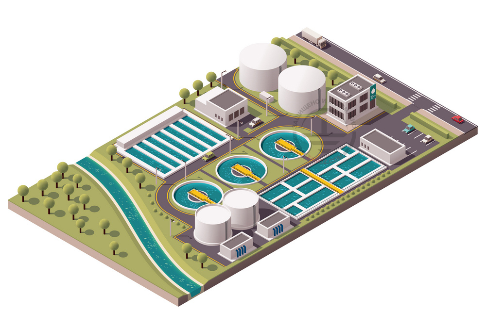
Treatment facilities are a set of process equipment, which allows treatment of drain waters to achieve the set standard values considering local requirements. Also, the treatment facilities are used to collect sedimentary silt of drain waters for its subsequent disposal. There are no special requirements to the lightning protection of treatment facilities according to regulatory documents. It is important to ensure the required reliability of lightning protection. Recently, the ZANDZ Technical Center has received a request to calculate the lightning protection system for the treatment facilities located in the Orenburg Region. Let us continue with more detailed review of our offered solution.
Calculation of lightning protection system for the treatment facilities located in the Orenburg Region
Facility: treatment facilities in the Orenburg Region.
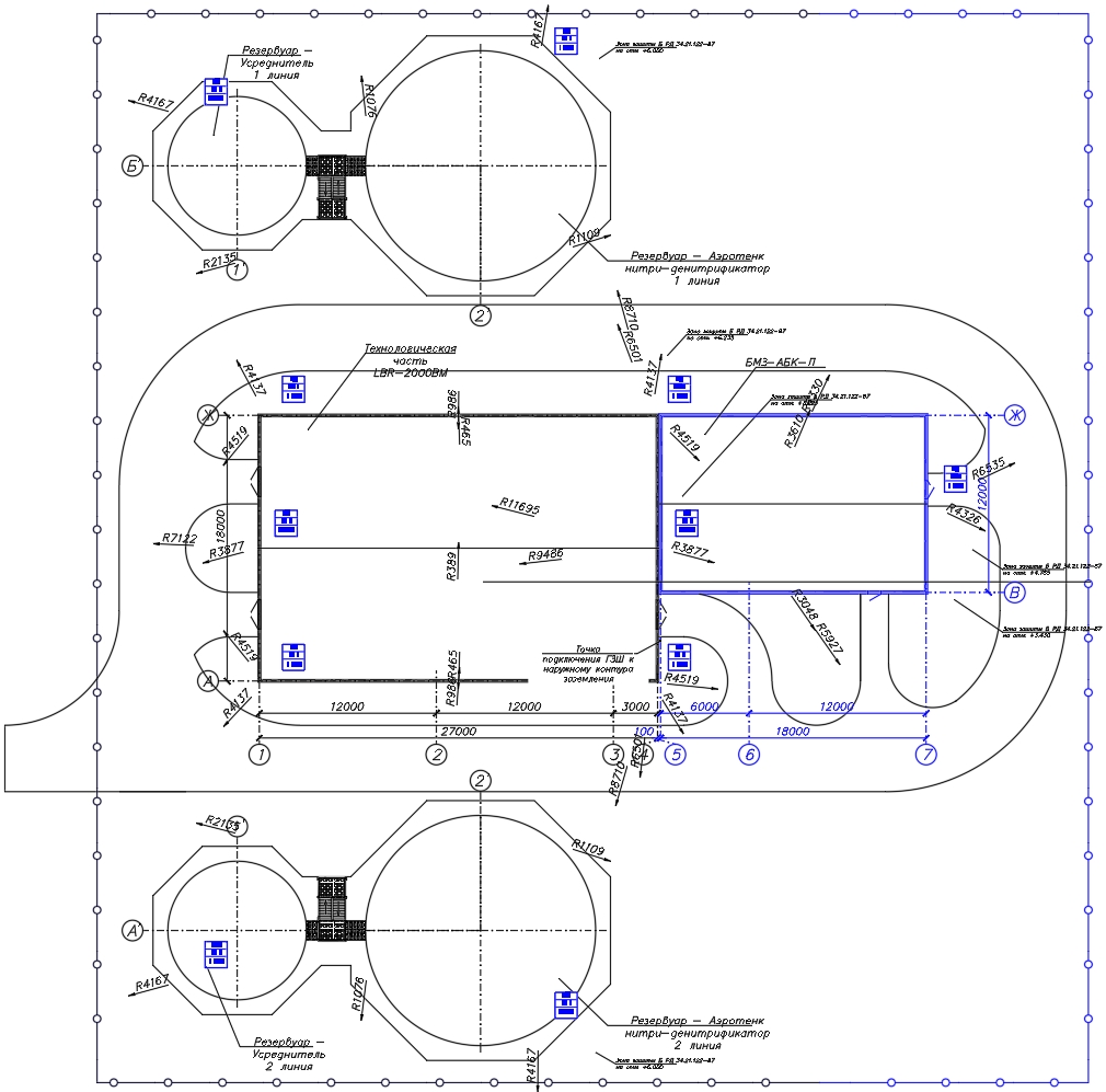
Резервуар-усреднитель - Stabilization tank
1 линия - Line 1
Резервуар-аэротенк - Air tank
Нитри-денитрификатор - Nitrifier-denitrifier
Технологическая часть - Process part
2 линия - Line 2
Точка подключения ГЗШ к наружному контуру заземления - Point of connection of a storm protection bus to the external grounding circuit
Figure 1. Facility plan.
Task: to perform calculations for the lightning protection system for the treatment facilities located in the Orenburg Region.
Protection of buildings against lightning strikes is provided by using lightning arresters. Lightning arrester is a device that is elevated over the protected facility, through which the lightning current goes into the ground bypassing the protected facility. It consists of a lightning rod that accepts the lightning discharge, a current collector, and a grounding electrode.
Solutions to meet the requirements to the lightning protection system for the treatment facilities in the Orenburg Region:
The activities were made in accordance with the Electrical Installations Code (EIC), Rev. 7, Chapter 1.7, SO 153-34.21.122-2003 Guidelines for Lightning Protection of Buildings, Structures, and Industrial Utilities (hereinafter referred to as SO), and RD 34.21.122-87 Guidelines for Lightning Protection of Buildings and Structures (hereinafter referred to as RD).
The protected facility is classified as a conventional facility in terms of lightning protection according to SO and to Category 3 according to RD.
A set of arrangements ensuring compliance with the lightning protection requirements is based on the following solutions:
- installation of 11 x 4 m lightning rods on the wall. It was considered that 0.7 m of the rod length are used for securing;
- lightning arresters are interconnected to arrange two current collectors using a zinc-plated wire D = 8 mm from each lightning arrester.
Current collectors are connected to an artificial grounding arrangement in 8 points. The distance between the lightning arresters should not exceed 20 m. The main conductor cables are mounted (with mounting step 0.6-1 m):
- on the slopes of the roof using terminals GL-11747A;
- on a gutter using clamps GL-11545A;;
- to drainpipes using clamps GL-11514N;;
- connection and branching of current collectors are made using clamps GL-11551A.
A set of measures to meet the requirements to the grounding arrangement is provided by the following solutions:
- installation of a grounding arrangement consisting of a horizontal electrode (a zinc-plated steel bar with cross-section 4 x 30 mm), depth 0.5 meter, and 16 vertical electrodes (rods made of copper-plated steel with the diameter 14 mm), 3 m long;
- interconnection of vertical and horizontal electrodes as well as attaching to the reservoir enclosures using a clamp ZZ-005-064;
- connecting a current collector with the zinc-plated bar protruding from the ground is made using a control clamp GL-11562A;
- the grounding arrangement design conforms to item 1.7.55 of the EIC. Grounding arrangements of the protection grounding and grounding for the lightning protection are common;
- connecting outputs of a steel bar for equalizing potentials 5 x 40 mm with the grounding arrangement are made using clamps ZZ-202-013.
The location of the elements of the lightning protection system and the grounding arrangement is shown in a drawing in a separate file. The indicated protection zone corresponds to zone B according to RD.
Calculation of a grounding arrangement resistance.
The estimated soil resistivity is taken to be 1000 Ohm ∙ m.
Warning! In case the Customer provided erroneous and limited soil data, the above calculation of a grounding arrangement is considered incorrect. If the soil resistivity differs from the calculated one, it is necessary to perform computations with a real value. If the normalized impedance of the grounding arrangement is exceeded, there must be introduced the design corrections.
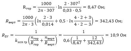
Гор - Hor
Верт - Vert
ЗУ - GA
Ом - Ohm
The estimated resistance of the grounding arrangement is 10.9 Ohm, which is less than the required grounding resistance 40 Ohm obtained by increasing the resistance of 4 Ohm by 10 times according to item 1.7.101.
Figure 2 shows hardware layout.
Table 1 includes the list of required hardware and materials.
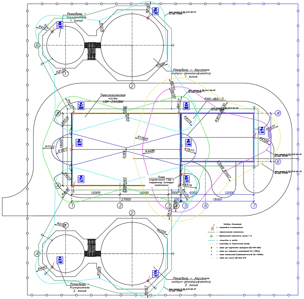
Резервуар-усреднитель - Stabilization tank
1 линия - Line 1
Резервуар-аэротенк - Air tank
Нитри-денитрификатор - Nitrifier-denitrifier
Технологическая часть - Process part
2 линия - Line 2
Точка подключения ГЗШ к наружному контуру заземления - Point of connection of a storm protection bus to the external grounding circuit
Условные обозначения - Legend
Figure 2. Hardware layout for the lightning protection for the treatment facilities in the Orenburg Region.
Table 1. List of material requirements.
Do you have any questions about lightning protection for the treatment facilities or other objects? Please, contact the ZANDZ Technical Center!
Related Articles: