To create a good and reliable grounding in a private house, there is a very simple and easy-to-implement solution that guarantees the result for a hundred years.It is installation of house grounding with the help of a ready-made, quickly assembled ZANDZ grounding kit, specially designed for such use.
Advantages
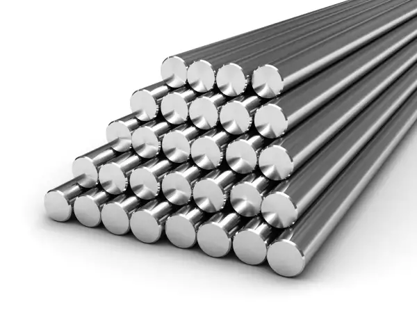
The main element of any grounding device - grounding electrode, presents itself a metal structure mounted in the ground.
ZANDZ ground electrode system, derived from the kit "Grounding in a single family house" - is an individual assemblable depth grounding electrode consisting of four 1.5-meter steel pins coated with a layer of electrical copper.
Advantages of such design and materials used:
- The service life of up to 100 years
- Simple assembling by one person without any special tools.
For the construction of the ground electrode system of the required length, pins 1.5 meters long are deepened into the ground one after another with the use of a striking tool (sledgehammer). A bolt clamp is used to connect the conductor with the electric board. - The minimum area occupied by the ground electrode system allows you to mount it in the basements, or close to the walls in the form of just one point. Small size minimizes necessary earthwork.
- No welding required *
- Grounding quality does not depend on the weather and season
* Connection of elements of grounding devices NOT made of ferrous metals is permitted by technical circular 11/2006 of the RosElektroMontazh association
Application restrictions
ZZ-6 "Grounding in a single family house" kit is designed for mounting in soft clay soils (for example, clay loam).
Mounting in dense clay soils is difficult, but possible (for exmaple, heavy clay).
Mounting in solid sandy and stony soils is impossible. This limitation is connected with the low energy impact of a hand tool (sledgehammer) used at the assembling.
For mounting of the ground electrode system in dense or solid soils we recommend using kits of modular grounding (On an individual page).
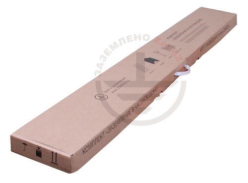
Information about packing:
Item: ZZ-6
The kit is packed in a box of firm cardboard with a plastic handle. Inside the box there are the details of the grounding kit, as well as the manual and a pair of brand-name labels to be placed on the door of the electrical board or other flat surfaces upon buyer's discretion
| ZZ-6 | |
| Weight: | 12 kg |
| Length: | 155 cm |
| Width: | 25 cm |
| Height: | 7 cm |
Dealers in Russia and CIS countries
You can buy ready-made ZANDZ grounding kits, as well as individual components, not only in our online store, but also at an amicable trading company with its own warehouse in the city.
Buying from a local dealer will save you time and money in bringing the goods from the central warehouse in Moscow. If the dealer has a sales area - you can find the kits and grounding components "live".
Grounding Kit ZZ-6
The ZZ-6 ready-made kit contains all the necessary parts for mounting an earthing switch, easily mated with each other.
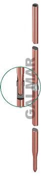
Copperplated clutchless ground pin (D17 mm / L1,5 m) 4 pieces
Kit base - a pin 1.5 m long with a thick copper coating (for maximum service life). One end is narrowed, and a blind hole is made on the end of the other for connecting pins to one another (to increase the total electrode length).
When mounting, the connection is automatically pressed, forming a very good electrical and mechanical contact.
For the assembling of clutchless pins, it is necessary to use a driving head, transmitting the striking force to the center of the pin.
| ZZ-6-1 | |
| The diameter of the rod: | 17 mm |
| Length: | 1.51 m |
| Weight: | 2.75 kg |
Details about manufacturing technology and testing of the coating are available on an individual page.

Driving head for mounting with a sledgehammer 1 piece
Hardened steel driving head is designed to transfer the instrument's impact energy (sledge hammer) to the center of the pin. It is located in the slot of the pin at the assembling.
| ZZ-6-4 | |
| Weight: | 0.12 kg |
| Length: | 70 mm |
| Diameter: | 16 mm |
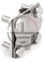
A clip for conductor's connection, 1 piece
Stainless steel profiled clamp with M10 bolts. Allows to connect a rod with a grounding conductor- round cross-section wire or a band (up to 40 mm wide).
Safe use of steel and galvanized wire is possible - for that purpose, there is a gasket inside the clamp, which prevents formation of galvanochemical connection between the steel / zinc and copper.
To prevent loosening of threaded joints "bolt-nut" spring washers are used (Grover washers / grover washers) installed between the clamping surface and the nut.
| ZZ-6-5 | |
| Weight: | 0.358 kg |
| Length: | 80 mm |
| Width: | 80 mm |
| Height: | 30 mm |
Additional materials
In addition only a copper wire with a cross section
of 16 or 25 mm² of a required length - to connect the mounted ground electrode to the electric board.
For maximum protection of the blind hole on top of the pin in an already assembled ground electrode system, it is possible to use silicone sealer, applied into this hole. It blocks penetration of moisture and dirt to the core pin, completely stopping the corrosion.
Before mounting
When placing the ground electrode system INSIDE the house the mounting location is determined for reasons of mechanical protection of the grounding conductor from that ground electrode system to the electric board, dryness of the premises, convenience of mounting pins into the ground. The best place is the position in the radius of 0.5 meters from the electric board in order to achieve the shortest length of the conductor. Maximum distance from the electric board is not limited.
When placing the ground electrode system OUTSIDE the house one must note that the grounding conductor must be laid to a depth of 0.5 - 0.7 meters in a pre-dug channel. This measure is mandatory and necessary to protect the conductor from damage during operation and to minimize weather / seasonal influence, which increases its service life.
Ground electrode system switch is mounted in the same channel. Input of the ground conductor through a wall is carried out inside a steel tube.
Required materials:
- ZZ-6 "Grounding in a single family house" kit
- copper wire / cable with a cross-section of 16 or 25 mm² of the required length. When mounting into the ground, a conductor with a minimum cross section of 25 mm² is required.
- Silicone sealer
Required tools:
- Striking hand tool weighing 300 - 1500 g: Sledgehammer or heavy hammer
- two wrenches or two pliers (to tighten clamp bolts)
The sequence of works at the mounting of the grounding outside the building
- Dig a channel 0.5 - 0.7 meters deep at the site of the grounding conductor placement
- Mount the ground electrode system in the prepared channel. It is necessary to use the list of operations "Procedure for mounting...." as a mounting manual.
- Place the grounding conductor into the channel
- Connect the ground electrode system with the conductor using the clip from the kit
- Connect the conductor to the electric board
- Cover the channel with earth
Connection of the grounding to the electric board
The connection is made with a copper conductor with a recommended cross-section of 16 - 25 mm². For example, with a special grounding conductor.
A special clamp is used to connect the grounding electrode to the conductor (included in the kit).
The procedure of the ground electrode system mounting
Sealing bushes made of stainless steel are put on the pins for easy transportation. Before installing the bushes must be removed.
Operations:
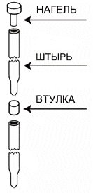
- Insert a driving head to the pin hole.
- Deepen the pin into the ground, hitting the driving head with the tool.
- Remove the driving head and put the bush over the mounted pin (wide side facing down).
- Insert the pin with its sharp-edge into the mounted pin with a sealing bush over it. The connection will be pressed in by itself during the mounting.
- Repeat steps 1-4 until getting the desired depth of the ground electrode. The last pin must be left at 20 cm above the ground. A sealing bush is not put on the last buried pin.
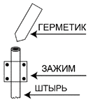
- Set the clamp to connect the grounding conductor, and having connected the conductor, tighten the screws with a maximum clamping force.
- Fill the pin hole with the sealer to prevent moisture penetration.
Example of grounding mounting in a single family house
See also full description of calculations and a video mounting of grounding on an individual page.
Is such a grounding enough? (parameters)
Ground electrode system from the Kit "Grounding in a single family house" ZZ-6
in clay soils (clay, clay loam) provides earth resistance of about:
| Soil | Grounding resistance, Ohm |
| Wet clay | 4 |
| Damp clay loam | 6 |
| Clay | 12 |
| Clay loam | 18 |
House grounding quality requirements
If you do not plan to connect lightning protection and gas equipment to grounding:
- in ordinary clay soils quality local (repeated) grounding, should be of recommended resistance not more than 30 ohms (With linear voltage of 220 V of a single-phase power supply or linear voltage of 380 V of a three-phase power supply)
- in sandy soil quality local (repeated) grounding, should be of recommended resistance not more than 150 Ohms(With linear voltage of 220 V of a single-phase power supply or linear voltage of 380 V of a three-phase power supply)
Requirements to the quality of grounding (special cases)
If grounding is used together with lightning rods:
- in ordinary clay soils grounding resistance should be not more than 10 Ohms (РД 34.21.122-87, p. 8)
- in sandy soil grounding resistance should be not more than 40 ohms (РД 34.21.122-87, paragraph 8;. For soils with a specific electrical resistance of more than 500 Ohm * m)
In this case, the ground electrode must include at least 3 vertical electrodes, spaced from each other at a distance of at least two depths of immersion of the electrodes (RD 34.21.122-87, p. 2.2.d).
For more information about application, see an individual page "Lightning protection and grounding".
If grounding is used to connect a gas boiler / gas pipeline:
- in ordinary clay soils its resistance must be not more than 10 Ohms (EIC 1.7.103; for all repeated groundings).
- in sandy soil, its resistance should be not more than 50 Ohm (PUE 1.7.103; for all repeated groundings; for soils with a resistance of more than 500 Ohm * m)
It is recommended to perform a ground electrode system as a single electrode (point like grounding). For more information about application, see an individual page " Gas boiler / gas pipeline grounding".
Choice of grounding system (TT / TN) for single family houses
In 2007, the management of the State Energy Supervision sent a letter (№10-04 / 481) to the Interregional Territorial Administration leaders and heads of the Directorate for Technological and Ecological Supervision of Rostekhnadzor, that in order to clarify and supplement the requirements of normative and technical documents in power engineering and implementation of safety measures for electrical installations technical circulars (TC) are prepared ( approved / agreed), which are recommended to use for guidance and application at the inspection of project documentation and putting of new and reconstructed electrical installations into operation:
- № 6/2004 from 16.02.2004 "About execution of the main potential equalization system at the entrance facility";
- № 7/2004 from 02.04.2004 "About installation of electric wirings above suspended ceilings and in parting walls";
- № 10/2006 from 01.02.2006 "About schemes of temporary power supply of construction sites";
- № 11/2006 from 16.10.2006 "About ground electrode and ground conductors";
Comment to TM №11 / 2006 "About ground electrodes and ground conductors" (from the developer of the technical memo: Mr. Shalygin A.A., ECC Chief of Moscow Institute of energy and energy efficiency) states:
In accordance with the instructions from item 1.7.59 the seventh edition of the EIC: "Electrical installation power supply with voltage up to 1 kV from the source with a dead-earthed neutral and grounding of exposed conductive parts with the help of ground electrode system not connected to the neutral (CT system) is allowed only in cases where the electrical safety conditions in a TN system can not be provided. For protection against indirect contact such electric installations must be supplied with automatic power off with the the mandatory use of the RCD... ".
Individual houses are an example of electric installation, where it is impossible within reasonable technical solutions to meet the requirements of electrical safety in the TN system, that should be connected to the overhead line of 0,4 kV with bare wires due to local conditions. The thing is that the neutral conductor of the overhead line can not be regarded as PEN-conductor by definition. In these circumstances, it is reasonable to use the system of protecting earthing TT to substitute bare conductors of overhead lines to self-supporting insulated conductors.
A RCD with a rated residual operating current of 300 or 500 mA is, as a rule, installed at the entry to such installation for an automatic power off. The grounding device resistance is selected of about 30 ohms and for soils with high volume resistivity of up to 300 ohm. With these parameters of a grounding device, a reliable operation of the RCD is ensured, and short-circuit currents are negligeable.
Later - in 2012 TM № 31/2012 "About execution of repeated grounding and automatic power off at the input of individual construction objects" was released. Its text (abridged):
Objects of individual housing construction, as a rule, receive power from a branch from the overhead lines of up to 1 kV.
For new construction objects and at the renovation, in accordance with the instructions of chapter 2.4 of the seventh edition of the EIC, air lines are made using self-supporting insulated wires and are referred to as ВЛИ.
Most of the existing facilities of individual construction are powered by overhead lines with the use of bare wires of overhead lines, made in accordance to the standards of Chapter 2.4 EIC edition 6 and earlier.
... The purpose of this circular release is to issue specific recommendations to ensure protection against indirect contacts in electrical installations, receiving power from the overhead lines and insulated lines to 1 kV. When choosing protection measures against indirect contacts in electrical installations, receiving power from the overhead lines and insulated lines up to 1 kV, one must be guided by the following:
- Since for the facilities, receiving power from the overhead lines with voltage up to 1 kV, the majority of consumers can not fulfill requirements on automatic shutdown due to low response ratio of short-circuit currents, installation of residual current devices (RCD) with a residual operating current of up to 300 mA at the input is mandatory .
Note. Installation of RCD with the differential trip current up to 300 mA at the input is mandatory in terms of fire safety.
- When powered by the insulated lines, the resistance of the repeated grounding with the consumer is selected on the condition of reliable operation of the RCD when the insulation is damaged (single-phase ground fault) at the disconnected PEN conductor of the insulated line branch. The resistance is calculated according to the current of the RCD's safe operation, equal to five-time- size of this current, but should be not more than 30 ohms. At the soil resistivity of more than 300 ohm * m the resistance may be increased up to 150 ohms.
- When powered from overhead lines, in accordance with the instructions of p.1.7.59 of EIC seventh edition and p. 531.2.3 of IEC 60364-5-53 (Russian analogue GOST Р 50571-5-53 is forthcoming), one should use protective grounding system TT. Parameters of the repeated grounding are selected in accordance with the instructions of p. 2 of the present technical circular.
- The use of the CT system is considered as a temporary (forced) measure. After the reconstruction of overhead lines and switching to insulated lines, it is necessary to use a system of protective grounding TN in electrical installations. For this, the switch on the input equipment should be set between N and PE busbars.
Installation of protective devices
We want to draw your attention to the fact that grounding of a house / summerhouse - is just one of several necessary measures for the organization of a high-quality power supply system in the house.
Use of grounding without protective devices (for example, RCD) - is DANGEROUS.
Equipotential bonding equalization system
Please note that for safety reasons operation of electrical appliances in the house the equipotential bonding system must be necessarily carried out (EIC 1.7.82).
This measure is the union of all electric conductive surfaces aimed to create one (equal) electrical potential for them. In case of any emergency a person who touches such surfaces (for example, body of the washing machine and a water pipe) - won't be harmed because ther will be no difference of potentials.
The main equipotential bonding system must interconnect the following conductive parts:
- protective conductor PE or PEN-conductor of the feed line in TN system
- ground conductor connected to the grounding electrical device in IT and TT systems
- ground conductor connected to the repeated ground electrode system at the entrance facility (if there is a ground electrode system)
- metal communication pipes entering the facility: hot and cold water supply, sewerage, heating, gas, etc.
- metal parts of the building frame
- metal parts of the centralized ventilation and air conditioning systems
- lightning protection grounding device of the 2nd and 3rd categories
- Grounding conductor of functional (working) ground electrode system, if there is one, and there are no restrictions to connect the working grounding network to the grounding device of the protective grounding
- metal sheaths of telecommunication cables;
Certificate
Certificate of Conformity РОСС RU.AГ66.Н00867 (voluntary certification):
-3.jpg)
-4.jpg)
ZANDZ. Certification in the territory of the EEU Customs Union
Certificate of conformity RU C-RU.АЛ32.В.05536 for the conformity of kits to the requirements
of the Technical Regulations of the Customs Union ТР ТС 004/2011 "About security of low voltage equipment":

An exemption letter about lack of necessity in a mandatory certification of components in the territory of the Customs Union countries:

Related Articles:
 Grounding in the cellar of the single-family house - is it possible?
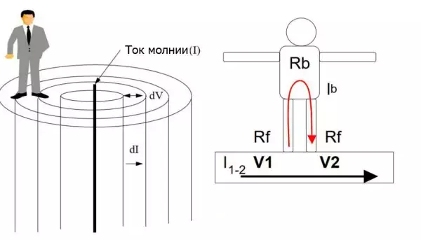 Step Voltage: Dangerous Obscurity and Reliable Protection
 Nature of Electrochemical Corrosion
 Public Safety in Land Transport in case of Direct Lightning Strike