... from the book "Grounding:answers to questions"
We are grateful to Alexander, the author of this interesting story.
============
I will probably start with the fact that this article in no way claims the title of an "expert opinion" or even "a brief guide on electric power supply." Here I will describe my choice of electricity supply and grounding system of an ordinary garage. I have to say - I studied to be an electrician and work as an electrician, and I am dealing with power supply devices of 10 kV and higher, that is why many moments in the 0.4 kV system were new (and, to be honest, interesting) for me. People who know, who are really experts in this voltage range may find something to fix in this article, for what we would be grateful.
It all started with the fact that I got an old garage (built in the beginning of 70th) for a relatively small price. I got it in a very "dead" state - dirty, messy and with a severely leaking roof. As a consequence, everything in the garage had been exposed to water for many years. The impact of that spread to the garage power supply devices, in simple words - wiring, and there was a characteristic tingling when you touch the wet plaster, in the depths of which it (wiring) decayed completely, it is hard to say what it was made of and how.
I decided to start the reconstruction of the garage with the organization of a reliable and secure electricity supply. An old introductory panel, located at the entrance of the garage, was not affected by water, the cable from the external distribution network to the shield was also in good condition, so I simply cut the the existing wiring from thw switchboard and powered the "construction" (perforator, grinder, etc.) by the extension cord from the double power board from the outlet on the switchboard.
I will not describe the repair itself, since it is not related to the topic of conversation (I repaired the roof and the water no longer flows into the garage). "I will jump" directly to its end, when the question about the organization a constant power supply, and in particular about protective grounding arose.
At first, I will describe the external network of my garage.
The surrounding single family houses and a few lines of garages, including ours, were powered from 0.4 kV overhead line, performed on wooden supports, there was no repeated grounding PEN on the supports. A tip was carried out from one of the supports to an old switchboard with a switch and a fuse (our IDD), repeated grounding PEN was absent. Further, to the common meter and from it - along the wall by a four-wire cable with rubber insulation in the pipe. There was a box above the gates of every garage, from which the "tip" to the garage was carried out. Actually the main problem was in these boxes: the cable outer insulation was in a good condition, but in making-off places the insulation was seriously worn out, cracked and was about to fall apart. It was very likely to get a burn off of one phase in such conditions or "zero" (which is more unpleasant) when touching it.
I decided to change the electricity completely, starting from the exterior outlet box. I put a new entrance cabinet with the meter, automation and RCD, from which the routing of socket, lighting and ventilation networks was made. The networks were installed along the external walls in plastic corrugated pipes, all equipment was IP 54 or IP 55, the wires-ВВГнгLS with the cross-section of 1.5 mm² for lighting and ventilation networks (total capacity of installed fans did not exceed 120 watts) and 2.5 mm² for the socket network. All wire connections were made by clamps of WAGO type.
Given the characteristics of the existing network, I began to consider the grounding system offered in p. 1.7.3 of the EIC, sequentially from system to system.
TN-C system was the easiest option (scheme 1).
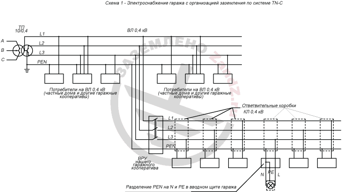
Scheme 1 electric supply of a garage with the organization of grounding on TN-C system
Потребители на ВЛ 0,4 кВ (частные дома и другие гаражные кооперативы) – consumers of high voltage line 0,4 kV (single-family houses and other garage cooperatives)
Ответвительные коробки КЛ 0,4 кВ – distributing boxes. Cable line 0,4 kV
ТП – transformer substation
ВРУ нашего гаражного кооператива - our cooperative input switching device
Разделение PEN на N и PE в вводном щите гаража – Separation of PEN to N and PE in the garage entrance switchboard
In this case, L and PEN were introduced into the switchboard, then it was enough to split PEN into N and PE in the entrance board, to which to attach the switchboard body, bodies of the lamps and grounding contact of outlets. Everything is quite simple, but in this case at the breakage of PEN (which was possible in the external network) phase 2 would get to the zeroed bodies of the equipment.
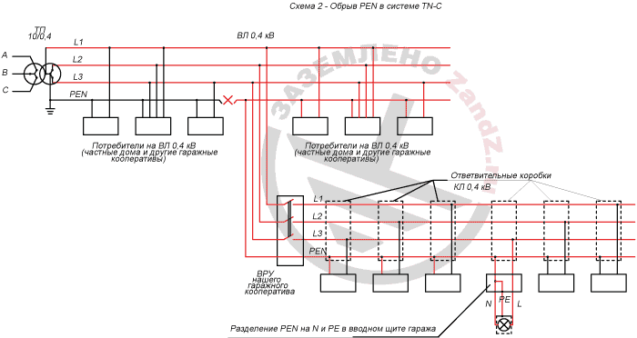
Scheme 2- PEN disconnection in TN-C system
ВЛ – high-voltage line
ТП – transformer substation
Потребители на ВЛ 0,4 кВ (частные дома и другие гаражные кооперативы) – consumers of high voltage line 0,4 kV (single-family houses and other garage cooperatives)
Ответвительные коробки КЛ 0,4 кВ – distributing boxes. Cable line 0,4 kV
ВРУ нашего гаражного кооператива – our cooperative input switching device
Разделение PEN на N и PE в вводном щите гаража – Separation of PEN to N and PE in the garage entrance switchboard
It would be possible to protect from such a scenario by a repeated grounding device at the garage input, having grounded on the PEN organized contour. But, most likely, my repeated grounding would have been the only one on the entire district, and in case of a "burn off» of PEN, for example, in the area of the substation, the whole operating current of a neutral wire, would rush to me. At a certain level of network load asymmetry, this current value could reach considerable values, which would lead to overheating of our PEN site and as a consequence to a possible fire (scheme 3).
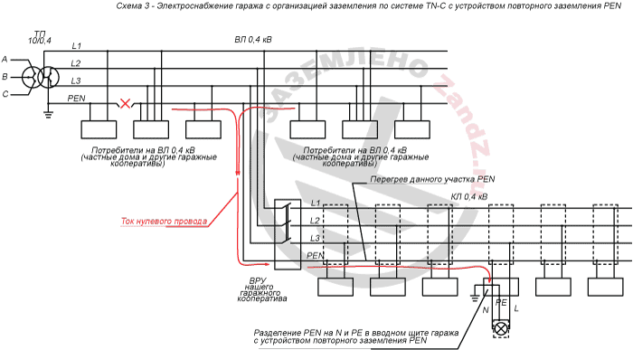
Scheme 3 Garage electric supply with the organization of grounding on TN-C system with the organization of repeated grounding
ВЛ – high-voltage line
ТП – transformer substation
Перегрев данного участка PEN – Overheating of this PEN section
Ток нулевого провода – neutral conductor current
Потребители на ВЛ 0,4 кВ (частные дома и другие гаражные кооперативы) – consumers of high voltage line 0,4 kV (single-family houses and other garage cooperatives)
Ответвительные коробки КЛ 0,4 кВ – distributing boxes. Cable line 0,4 kV
ВРУ нашего гаражного кооператива – our cooperative input switching device
Разделение PEN на N и PE в вводном щите гаража – Separation of PEN to N and PE in the garage entrance switchboard
TN-S system was not considered, because separation of PEN to PE and N at the substation with several hundred meters of PE wire to the consumers at a modest repair garage was not included into my plans.
Then was TN-C-S system (Scheme 4).
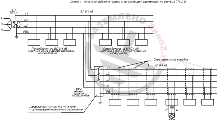
Scheme 4 electric supply of a garage with the organization of grounding on TN-C-S system
Потребители на ВЛ 0,4 кВ (частные дома и другие гаражные кооперативы) – consumers of high voltage line 0,4 kV (single-family houses and other garage cooperatives)
Ответвительные коробки КЛ 0,4 кВ – distributing boxes. Cable line 0,4 kV
ТП – transformer substation
ВРУ нашего гаражного кооператива – our cooperative input switching device
Разделение PEN на N и PE в вводном щите гаража – Separation of PEN to N and PE in the garage entrance switchboard
For the organization of this system, it was necessary to separate PEN to PE and N and to IDD of the garage cooperative with the organization of a repeated grounding and then bring a five-wire cable. There arouse the question regarding the repeated grounding. On one hand, the norms do not limit the value of the repeated grounding resistance. On the other hand, in this particular case, when at the breakage of PEN, the repeated grounding turned out to be the only remaining in work, its resistance, in my opinion, should have been not more than 4 ohms. But the main constraining factor was, the so-called, social. I haven't seen some owners of the cooperative garages at all, and the bushy grass in front of the gate certified that they were not going to appear there. The rest of my neighbors were also not up to the grounding system, because they appeared there once a month. The perspective to reorganize the entire cooperative network and make a normal contour alone did not inspire me at all.
And finally, the TT system.
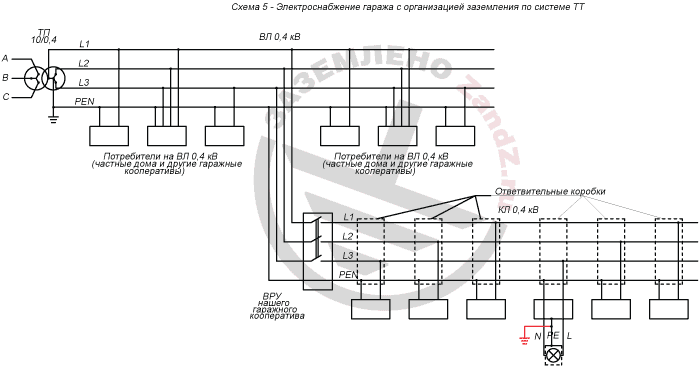
Scheme 5- electric supply of a garage with the organization of grounding on TT system
Потребители на ВЛ 0,4 кВ (частные дома и другие гаражные кооперативы) – consumers of high voltage line 0,4 kV (single-family houses and other garage cooperatives)
Ответвительные коробки КЛ 0,4 кВ – distributing boxes. Cable line 0,4 kV
ТП – transformer substation
ВРУ нашего гаражного кооператива – our cooperative input switching device
According to p. 1.7.59 of EIC "electrical power supply with the voltage of up to 1 kV from the source with a dead-earthed neutral and grounding of exposed conductive parts with the help of a ground electrode, not connected to the neutral (TT system) is allowed only in cases where electrical safety conditions in the TN system cannot be provided." After evaluating my technological and financial capabilities, simply to say having thought what can I do and how much it will cost for me, I realized that my choice is between TN-C and TT system. At the same time, ensuring of safety in a TN-C electrical system was a big question. In the end, the choice was made in favor of TT. At the same time according to the same paragraph 1.7.59 fairly low demands were raised to the grounding contour . So at the application of an RCD with the tripping current of 30 mA, the total ground electrode and grounding conductor resistance must be just less than 50 / 0,030 = 1667 Ohm! It was quite a realistic object even for a non-professional. Of course, I was not "carried away" by the opportunity to mount a contour in the form of a reinforcement piece, hammered 1 meter deep into the ground. There was a clay loam with crushed rock in the garage area. The contour of four pipes with the diameter of 25 - 30 mm with wall thickness of 2.5 -3 mm, pipe length 2.5 m. Two pipes were put in front of the garage door, the distance between them - 2.4m. Two other pipes were put in an inspection pit with the distance of 2.2 m between them. All four pipes were "tied" with a tape 40 x 4, all connections were naturally welded (scheme 6).
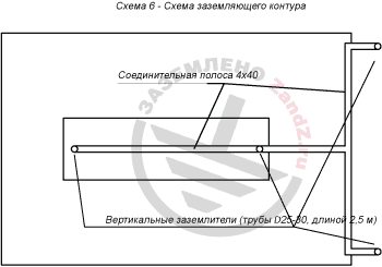
Scheme 6. Grounding contour scheme
Соединительная полоса 4Х40 = connection strap 4x40
Вертикальные заземлители (трубы D25-50 длиной 2,5 м) - Vertical ground electrodes (pipes D25-50 2,5m long)
To test the contour, I invited a specialist from the electrical laboratory. According to the measurements, contour resistance in summer was 5.8 ohms, short circuit current - 196 A. That is,the machine for 16 A set for the socket network should have worked in 0.4 seconds. But still I did not refuse to install RCD in accordance with the requirements of that paragraph. 1.7.59. Entrance switchboard scheme is shown in Scheme 7.
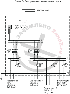
Scheme 7 – electric scheme of the entrance switchboard
Розеточная сеть ВВГнгLS 3*2,5мм – socket network ВВГнгLS 3*2,5 mm
Освещение 1 ВВГнгLS 3*1,5мм – Lighting 1 ВВГнгLS 3*1,5мм
Освещение 2 ВВГнгLS 3*1,5мм – Lighting 2 ВВГнгLS 3*1,5мм
Вентиляция ВВГнгLS 2*1,5мм – Ventilation ВВГнгLS 2*1,5мм
Useful materials:
- Grounding in a single-family house
- Modular grounding
- Consultations on the selection, design and installation of grounding and lightning protection systems
Related Articles:
 Grounding in the cellar of the single-family house - is it possible?
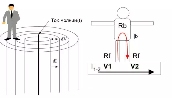 Step Voltage: Dangerous Obscurity and Reliable Protection
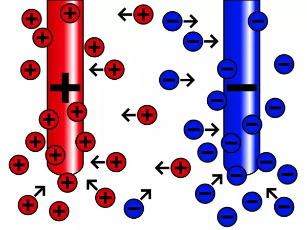 Nature of Electrochemical Corrosion
 Public Safety in Land Transport in case of Direct Lightning Strike