Like in other elements of the system's electric circuit, damage may occur on overlead power lines due to the violation of operational insulation. Wire breakage or breakdown of insulators etc. The reasons cmay cause current flow through the damaged support, and in some cases through the neighboring ones. This process is accompanied by the appearing potential on the support and, hence, stepper touch voltages and step voltage. To protect people who are near the damaged support, the supports are connected to special grounding devices for the reduction of current spreading resistance in the ground. The potential may not appear on wooden supports , so protective grounding is not carried out for them, even if there are metal crossarms. Protective grounding on overhead line supports with the voltage above 330 kV is also not carried out because of presence of high speed protections and a significant complication of the grounding device to ensure safe quantities of touch and step voltages.
In addition, grounding of supports is performed in the presence of lightning protection means. The main mean of lightning protection on overhead lines is hanging of the ground wire. The grounding device is designed to drain surge currents into the ground, which are resulting from a direct lightning strike onto the supports or ground wires, as well as to reduce the stress on the line insulation at the same time. Also protective spark discharges , pipe and valve-type arresters, surge arresters, long-spark arresters and multi-chamber arresters are connected to the grounding device.
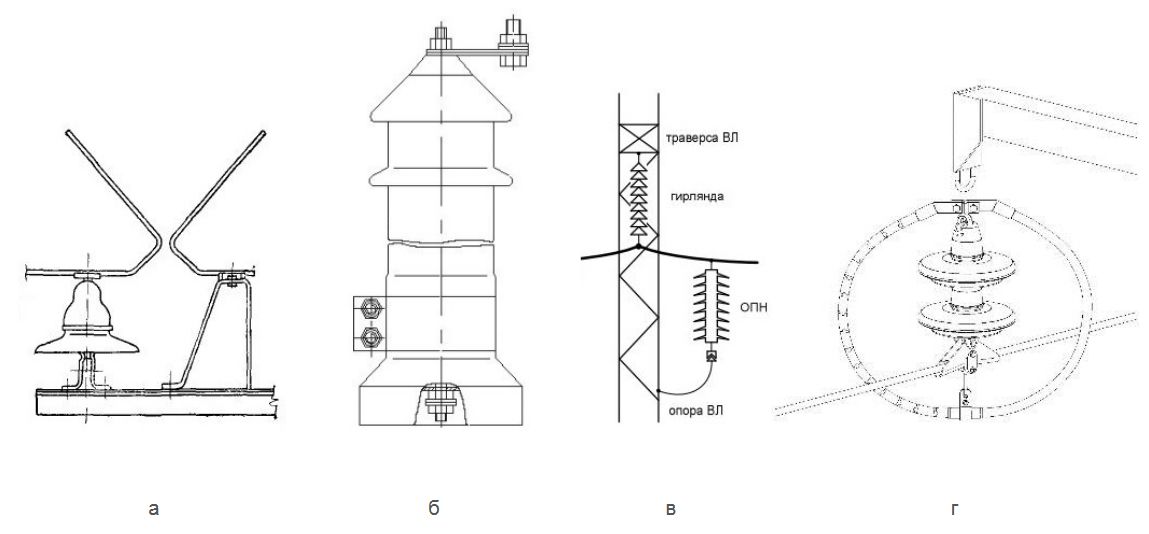
Picture 1 - Means of lightning protection of overhead transmission lines:
a) a spark discharger; b) valve-type arrester; c) surge arrester; g) long-spark arrester
Also, metal and concrete supports of HV lines 110-500 kV are grounded without any means of lightning protection, if it is necessary under the terms of provision of relay protection and automation.
Сonstruction of metal suports or longitudinal reinforcement of concrete supports are used as earthing leads on HV lines. The earthing leads on wooden and reinforced-concrete supports are made of round steel with a diameter of not less than 10 mm or a stranded wire with cross-section of not less than 35 mm2, if there are no special connecting rods. The number of leads should not be less than two. One end of the earthing lead is connected to the ground electorde, and the second to the groundable element. Groundable elements are connected to the metal support and the support at the bottom of its trunk is connected to the ground electrode system.
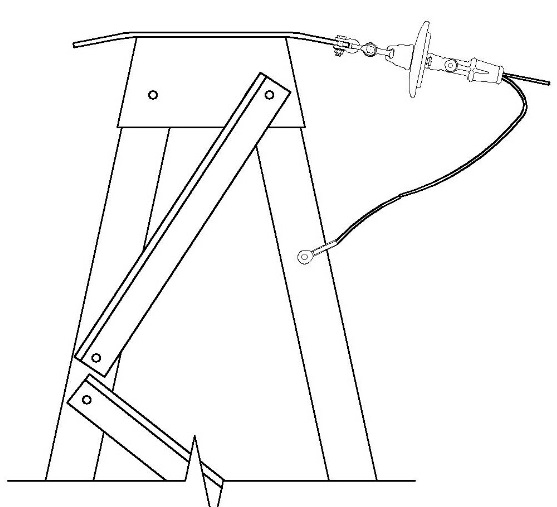
Picture 2 - Connection of the groundable elements to the ground electrode system on metal supports
Electrical Installation regulations govern the greatest resistance of the grounding device of the supports, depending on soil resistivity, height of supports, number of circuits of overhead lines, number of lightning outages, height of HV location abovethe sea level, type of location (populated / unpopulated) on which the overhead line is laid. Resistance values should be taken in summer time, that is, excluding soil freezing.
For the HV line supports with voltage of up to 35 kV, the resistance of the grounding device should be provided only by artificial ground electrodes. For the supports of 110 kV in soils with resistivity of 1000 Ohm ∙ m reinforced concrete footing (prefabricated, monolithic, pile, stuffed) can be used as natural ground electordes. The footings should not have waterproof polymer materials and it is necessary to provide a metallic bond between the anchor bolts and the footing reinforcement.
Artificial ground electrodes of supports present themselves metal conductors, which are in direct contact with the ground. Design solutions made at the design of a grounding device, depend on the type of the foundation support. Location and linear dimensions of the artificial ground electrodes must be coordinated with the value of soil resistivity and location of the support pillars. It is recommended to fulfil a grounding device in the form of groups of ground electrodes located around each support pillar in order to create multiple ways to lightning current or damage flowing from the support into the ground, and provision of an adequate full use of spreading conductivity of single ground electordes.
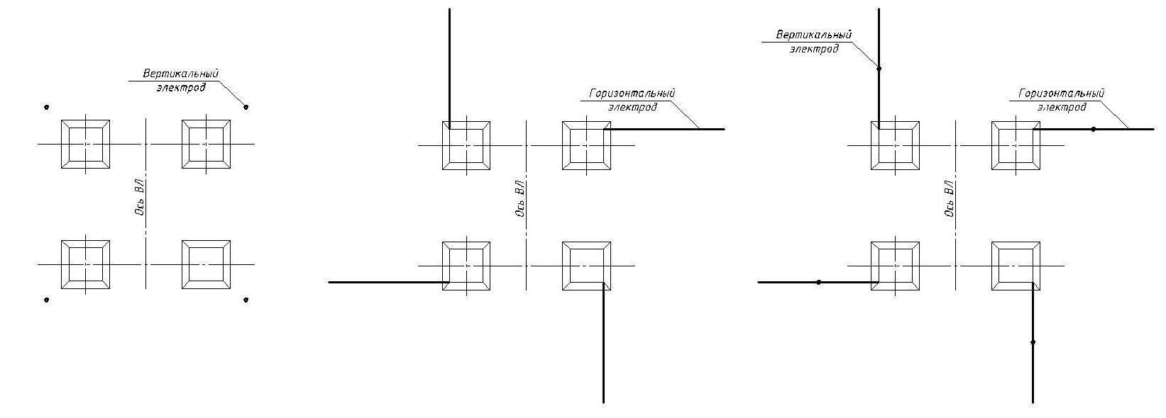
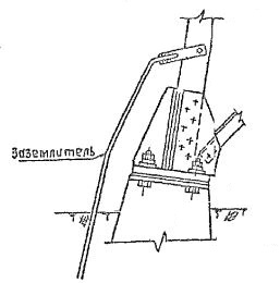
Picture 3 - Different configurations of a grounding device
Depending on soil resistivity and type of footing, it is reasonable to use some or other structural designs of grounding devices.
In cases where the conductivity of lower soil layers is much lower than of the upper ones, as well as at the use of piled footings it is recommended to mount vertical electrodes. They very well drain pulse currents of lightning strikes. Deep-laid ground electrodes occupy a small area and due to the great depth provide a small amount of current spreading resistance. When designing deep ground electrodes, it is important to choose a calculated value of soil resistivity, considering its heterogeneity, and to determine the optimal length of a unit electrode.
When the conductivity of the surface soil layers is high enough, you can apply extensive horizontal ground electrodes. Also, this solution is used in stony and rocky soils, where it is impossible to bury vertical ground electrodes. In areas with very high soil resistivity, application of continuous horizontal electrodes connecting several supports (the so-called balances) can be effective.
See also:
- Free webinars for designers with Professor E.M. Bazelyan
- Free webinars for designers with Dr. M. Loboda
- A series of articles "Lightning protection of oil and gas facilities"
- A series of articles "Lightning protection of residential and public buildings"
- Grounding in lightning protection - design FAQ
- Advices on the selection, design and assemblage of grounding and lightning protection systems
Related Articles:
