1. Description
Today it is hard to imagine our life without the daily use of various electrical appliances. However, the use of electricity is insecure without protective systems. There are cases where the protective devices (fuses, circuit breakers etc.) may fail, resulting in damage to the internal insulation. Thus, overvoltage occurs on the metal housings of equipment. To protect people from electric shock during the operation of household appliances, various protective measures are used, which include neutral grounding. This article explains what are the features of neutral grounding as a way to protect power grids, when it is applied and how it differs from the protective grounding.
Neutral grounding is used to ensure the electric safety of systems with PEN, PE and N conductors. These include grids with dead-grounded neutral: TN-C, TN-S and TN-C-S. The main difference in the arrangement of neutral grounding for these systems is in the way of connecting protective neutral and functional conductors.
TN-C neutral grounding system
Today, TN-C neutral grounding system is considered outdated, as it prevails in the buildings of the old housing stock. It is characterized by the presence of the protective and neutral functional PEN conductors combined along the entire length. It is used in three-phase power mains. Its use is forbidden in group and single-phase distribution grids. This system is simple enough to arrange, but it does not provide a sufficient level of electrical safety, which makes it impossible for the use in the construction of new buildings.
TN-C-S neutral grounding system
It is an improved version of TN-C neutral grounding system that ensures electrical safety in single-phase networks. At the point of branching a three-phase line into single-phase lines, the combined PEN conductor is divided into PE and N conductors that are led to single-phase consumers. This neutral grounding system, with a relatively small rise in costs, has a higher level of security.
TN-S neutral grounding system
It is considered the most sophisticated and safe neutral grounding system. Its operation is based on the separation of neutral protective and neutral functional conductors over the entire length. All all metal parts of the electric installation are connected to neutral PE protective conductor. A transformer substation with the main grounding is installed to avoid double grounding.
Electrical safety with neutral grounding
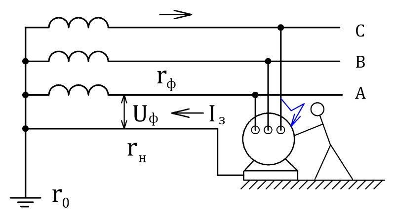
When using neutral grounding it is important to remember that the short-circuit current should reach a value sufficient to trigger the electromagnetic circuit breaker or melt the fuse. Otherwise, the short-circuit current will freely flow through the circuit, which will lead to an increase in voltage at the damaged section and on all the neutral-grounded elements of the electrical installation to the point where the probability of electric shock from touching the appliance housing will increase many times. It turns out that the reliability of the neutral grounding system is mostly determined by the reliability of the neutral protective conductor. That's why strict requirements are set to such conductors by para. 1.7.121 - 1.7.126 of PUE-7. A carefully laid neutral conductor is distinguished by its color code - yellow stripes on a green background. In addition, it is necessary to check its condition regularly. It is prohibited to install protective devices on the neutral conductor, as when triggered, such devices can damage it. Neutral wires connected with each other and with metal components of electric installations exposed for touch by users need to have a good contact and be accessible for inspection. See p.p. 1.7.39, 7.1.40 PUE-7. The resistance in bolted connections with the parts of electrical installations shall not exceed 0.1 ohms. The measurement of resistance in the phase-zero" loop " is performed at work acceptance stage, at major overhaul and renovation of the power mains, as well as within periods prescribed by the regulatory and technical documentation. Measurements in the disconnected electrical installation are carried out with a voltmeter-ammeter. In addition, the resistance of neutral ground and re-grounds, as well as the dependence of automatic protection device triggering time from the short-circuit current shall be regularly checked.
To reduce the electric shock in case of breakage of the neutral conductor, it is recommended to carry out a re-grounding with a resistance of fewer than 30 Ohms per every 200 m of lines and poles. Natural ground electrode systems are usually used for this purpose.
2. Neutral grounding standards
Technical requirements for the arrangement of protective neutral grounding systems are defined by the following documents:
- Electrical installations code (PUE), section 1.7,
- GOST R 50571.5.54-2013 (para. 543),
- GOST 12.1.030-81 (para. 7).
The neutral grounding operation is based on the automatic disconnection of the damaged section of the mains. The disconnection time shall not exceed the values specified in paragraph 1.7.79 of PUE-7.
The maximum allowable disconnection time for an TN system is
| Rated phase voltage Uo, V | Disconnection time, s |
| 127 | 0.8 |
| 220 | 0.4 |
| 380 | 0.2 |
| more than 380 | 0.1 |
Neutral functional and protective conductors shall have a resistance sufficient for protective disconnection. The active and inductive resistance of conductors form the full resistance of "phase-zero" loop. The active resistance of conductors depends on their length, resistivity and cross-section of the material. Inductive resistance is different for copper and steel conductors. For a steel wire, they are inversely related to the current density and the perimeter/cross-section ratio of the conductor. The inductive resistance of steel conductors is higher than that of the copper ones. Paragraph 1.7.126 of PUE-7 sets the smallest cross-sectional areas for protective conductors in cases when they are made of the same material as the phase conductors. The cross-section of the protective conductors made of other materials must be equivalent in conductivity to given values.
The smallest cross-section of protective conductors
| The cross-section of phase conductors, mm2 | The smallest cross-section of protective conductors, mm2 |
| S ≤ 16 | S |
| 16 |
16 |
| S> 35 | S/2 |
A two-wire line consisting of functional and protective conductors forms one large coil, the mutual induction resistance of which (recommended value for calculations is 0.6 Ohm / km) depends on the line length, wire diameter and spacing between them. The resistance of power supply neutral grounding should not exceed 2.4 and 8 ohms respectively at line voltages of 660, 380 and 220 V for a three-phase power source (please see para. 1.7.101 of PUE-7). The increase of short-circuit current is achieved by lowering the transformer and the loop resistance. Delta-star circuit is used for this purpose. The windings of large transformers have a small resistance anyway. A lower resistance of neutral grounding lines is achieved by making them short and simple, increasing the cross-section of conductors, or substituting steel wires with non-ferrous wires with a low inductive resistance. The greatest resistance of the neutral protective conductor must not exceed the double resistance of the phase conductor. By reducing the distance between them, it is possible to reduce the external inductive resistance. Reducing the resistance of re-grounding electrodes and bringing them closer to the load units helps reduce the current on the neutral-grounded parts of equipment. The connection of all grounded metal structures of the building to the neutral conductor increases the potential of the floor surface where a person can stand, thus significantly reducing the voltage of touch to a value of 0.1 to 0.01 Us.
3. Where neutral grounding is used
Neutral grounding is arranged at industrial facilities often located in the buildings where a power supply source (generator or transformer) is installed, to ensure the safety of electrical installations of various designations, and to increase the noise immunity during their operation. According to paragraph 1.7.101 of PUE-7, the neutral grounding of electrical installations should be carried out subject to the following conditions: at the voltage of 380 VAC and higher and 440 VDC or higher - in all electrical installations; at rated voltages higher than 42 VAC but lower than 380 VAC or higher than 110 VDC but lower than 440 VDC - only in areas with high risk, as well as in particularly dangerous and outdoor installations. All electrical equipment of industrial facilities is connected to a common ground loop and interconnected with a metal grounding bus. A complete list of parts to be connected to a neutral grounding system is specified in section 1.7 of the Electrical Installations Code (PUE-7). Electrical equipment which does not require neutral grounding is also listed there. Neutral grounding systems are almost never used in residential buildings. Grounding in new housing developments is arranged centrally. Modern appliances have three-pin plugs. One is connected to the housing of the appliance. Grounding for an individual apartment is done by connecting all parts and housings of domestic appliances to a ground electrode system. In these cases, neutral grounding is not necessary. Old houses usually connected under TNC system may not be grounded at all. The modernization of power mains in such houses should be done by a specialized electrical company. However, tenants of these houses often arrange neutral grounding on their own, wich is forbidden in this case and is not a safe way to ensure protection in the residential sector. As we've already mentioned, the requirements for the arrangement of protective neutral grounding are defined in special regulations. However, mistakes are often made in the process of implementation of this power mains protection method, which prevents its intended use. It is a mistake to believe that it's better to arrange grounding as a loop separate from the neutral conductor because there is no resistance of a long PEN conductor from the appliance to the substation ground electrode system. In fact, however, the grounding resistance is much higher than that of a long conductor. In case if the phase contacts the housing of appliance grounded in such a way, the short-circuit current may not be sufficient to trigger the protective circuit breakers. In this case, the voltage on the housing reaches a value hazardous to the user. Even if a small amperage circuit breaker is used, the time required by PUE for the automatic disconnection of the damaged line from the grid is not met.
4. How neutral and protective grounding differ
Neutral and protective grounding are similar in their designation: their purpose is to protect users from electrical shock. However, the methods and principles of this protection are different. Ensuring the safety of electrical mains with the neutral grounding system was discussed in detail earlier in this article. Protective grounding is based on the forced connection of electrical installations to the ground in order to reduce touch voltage to a safe value. The excess current that flows to the housings of electrical installations is drained directly into the soil through the grounding portion. A ground loop of a triangular configuration is used as a ground electrode system. Its resistance should be less than the resistance in other sections of the circuit. The difference from the neutral grounding is in
- the way to protect electrical mains. Protective grounding reduces the touch voltage; neutral grounding disconnects a damaged electrical installation from the mains. This virtually eliminates electrical shock, and from this viewpoint, it is a more effective way of protection in industrial plants. However, if we talk about the reliability of protection in the process of operation, the neutral grounding gives way to protective grounding due to a greater likelihood of the neutral conductor damage and the probable changes in the "phase-zero" loop resistance.
- Application patterns: Protective grounding is used solely for the protection of insulated neutral mains (TT and IT systems). Neutral grounding is used in dead-grounded grids (TN-C, TN-S and TN-C-S), where PEN, PE or N conductors are present.
- Type of arrangement: In terms of simplicity and accessibility, neutral grounding is a more complicated and time-consuming method of protection that requires technical knowledge and skills for a proper choice of the method and mid-point of neutral grounding. In the case of protective grounding, individual parts of the collector are connected to the ground. It is enough to read a household appliance manual for this purpose.
5. Conclusion.
The role of neutral grounding for the operation of industrial electrical installations cannot be overestimated. By disconnecting a damaged electrical installation from the mains in case of insulation breakdown, neutral grounding serves as a reliable way to protect people from electric shock. In order to effectively ensure the electrical safety, strict compliance of the structural elements of neutral grounding system to relevant standards, as well as careful and regular monitoring of their condition are needed. The choice of neutral grounding vs. protective grounding depends on the method necessary to protect various power grid systems.
See also:
- Grounding. What is it and how to make it.
- Lightning protection and grounding
- Useful materials for designers: articles, recommendations, examples
Related Articles:
 Grounding in the cellar of the single-family house - is it possible?
 Step Voltage: Dangerous Obscurity and Reliable Protection
 Nature of Electrochemical Corrosion
 Public Safety in Land Transport in case of Direct Lightning Strike