Ground conductor's conductivity use factor is an index that defines the mutual influence of the grounding electrodes in the ground loop (The ratio of the actual conductivity of the group conductor to its highest possible conductivity).
The factor is directly dependent on the distance between the electrodes and has a negative impact on the total earth resistance of the electrodes when reducing this distance (actual conductivity of the ground conductor decreases).
The physical meaning of the factor
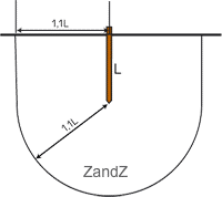
Each grounding electrode in the ground has a certain volume in the form of some hemisphere - near-electrode working area, which puts maximum (90%) impact on the earth resistance of this electrode. The diameter of the zone is approximately 2.2 lengths of the ground electrode (L) in the ground.
When more than one ground electrode is required for the construction of the earthing they should be located not closer than at the distance of 2.2 of the electrode leghts (L) in all directions for a maximum effect.
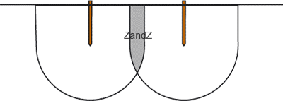
If multiple ground electrodes are too close to each other, this grounding scheme becomes ineffective as working near-electrode areas overlap - it decreases the working volume of these zones and, therefore, decreases the efficiency of each grounding electrode.
Also, the effect of reducing the efficiency of the grounding electrodes was noticed when using large number of them (up to 3-time increase of the total earth resistance) regardless of the distance between them.
Participation in the calculation formula
In the formula of the grounding calculation for a multi-electrode ground conductor (ground loop) the use factor is in the denominator.

The coefficient for equal vertical ground conductors have the following values:
- from 1 (that is, it does not affect the grounding resistance) - with the distance between the grounding electrodes equal to their double depth and their small number
- to 1 / N (that is, additional electrodes do not contribute anything to the reduction of earth resistance) - at the distance between the grounding electrodes, approaching to 1/30 of their depth
Values for vertical electrodes
Digital values of the use factor with considering the effect of the ground conductor, for vertical grounding electrodes arranged in series and in a closed loop:
Placement in a row
| The ratio of the distance between the electrodes to their length | The number of the electrodes | Use factor |
| 1 | 5 | 0,7 |
| 1 | 10 | 0.6 |
| 1 | 15 | 0.53 |
| 1 | 20 | 0,5 |
| 2. | 5 | 0.81 |
| 2. | 10 | 0,75 |
| 2. | 15 | 0,7 |
| 2. | 20 | 0.67 |
Placement in a closed circuit
| The ratio of the distance between the electrodes to their length | The number of the electrodes | Use factor |
| 1 | 5 | 0.65 |
| 1 | 10 | 0.55 |
| 1 | 15 | 0.51 |
| 1 | 20 | 0.45 |
| 2. | 5 | 0,75 |
| 2. | 10 | 0.69 |
| 2. | 15 | 0.66 |
| 2. | 20 | 0.63 |
When the number of electrodes is more than 80 - the use factor on average
is equal to 0.4 if the distance between the electrodes is equal to their single and double depths.
Value for the modular grounding
For kits of modular grounding ZANDZ at the configuration of the ground conductor in the form of three electrodes at a distance of 5 or 10 meters (for kits ZZ-000-015 and ZZ-000-030 respectively) - the use factor is 1.
Values for electrolytic grounding
Digital values of the factor not considering the effect of the ground conductor for horizontal grounding electrodes of electrolytic grounding ZANDZ 2.4 meters long, placed in a row at a distance of 6 meters from each other:
| The number of the electrodes | Use factor |
| 2. | 1 |
| 5 | 0.99 |
| 10 | 0.93 |
| 20 | 0,8 |
Related Articles:
 Why Cannot Vertical Earthing Devices Be Installed Close to Each Other?
 Electrolytic Grounding in Permafrost Soils: Should Vertical of Horizontal Electrodes Be Used?