Vertical rods of small length
When using vertical earthing devices of small length (about several meters long) to provide the required earthing, several rods are installed into the earth, which are interconnected in parallel. This is natural since this array takes a particular area, a temptation occurs to save the space and install the rods closer to each other. But indeed, you should not do it. There is a particular distance, and you should not install the rods closer than that. This article describes this distance and why it is so bad to install the rods too close.
Mutual Shielding of Electrodes
If two electrodes (rods) are located at an infinitely large distance from each other, than in case of their parallel connection, an ideal conductor with the zero resistance, the general conductance of such earthing device relative to the earth will be equal to the sum of conductances of both rods relative to the earth (let me remind you that the conductance is a value inverse to the resistance). This rule may be generalized to the larger amount of electrodes, and then their conductances are also summed up.
What happens if the distance between the parallel electrodes is less than their lengths or comparable to it? The conductance of such earthing will be less than the sum of conductances of two separate rods relative to the earth. Such phenomenon is called the mutual shielding of electrodes This, in turn, is caused by the so-called current repulsion.
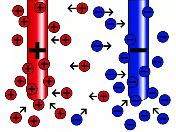
The major factor providing the electrical conductivity of the soil is the presence of moisture containing the dissolved salts. As a result, the electrolyte is formed. When the electrical current flows through the electrolyte, positive ions move to the negative electrode (a cathode), while negative ions move to the positive electrode (an anode). For example, is we use copper electrodes, they will function as anode. And since the electrodes are interconnected by the conductor having a low resistance, their potentials relative to the earth will be almost the same.
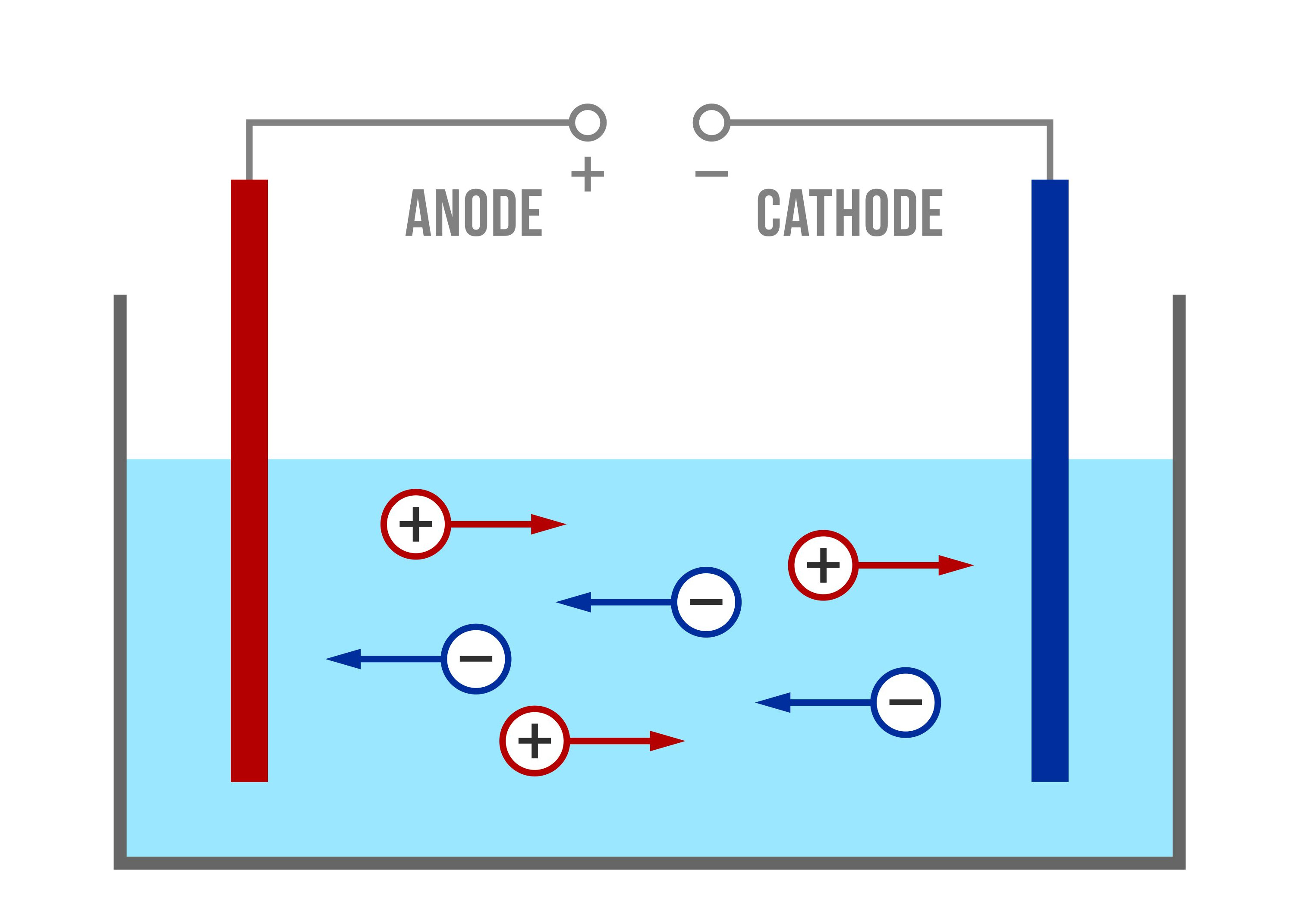
Ion Conductivity in the Electrolyte
Ion Conductivity in the Electrolyte
The electrical current is associated with the physical ion transfer. With the close arrangement of electrodes, ions with the same charge will repel, which reduces their movement intensity. This is the current repulsion. As a result, it decreases the general conductivity of the system made of parallel electrodes.
Determining a Minimal Distance between the Vertical Earthing Devices
Too large distance between the vertical electrodes is not only unreasonable use of the earth but also large lengths of the wires connecting the electrodes. The longer the wires, the higher their resistance. On the contrary, if we install rods too close to each other, it will reduce their efficiency. The following thing follows from it: there should be an optimum range of distances between the vertical earthing electrodes within which the best technical and economic values are provided.
Protection of structures from the lightning is a very critical task; therefore, its earthing parameters consisting of several electrodes are rigidly stated, including the distance between the electrodes. For example, according to the effective Instruction RD 34.21.122-87, Clause 2.2, for separate lightning arresters, the suitable option is an "artificial earthing device consisting of three or more vertical electrodes with the length not less than 3 m combined with a horizontal electrode, with the distance between the vertical electrodes not less than 5 m".
If the earthing is used only to provide the operation safety of electrical installations, the target indicator is the required earthing resistance. The method of calculation based on the so-called utilization ratio is provided here. The higher the utilization ratio, the more efficient the earthing. Note that the utilization ratio depends not only on the distance between the electrodes, but also on the number of electrodes as well as on the topology of their installation (with the same minimum distance between the electrodes, their row-by-row arrangement provides a better utilization ratio that with their installation in a closed circuit).
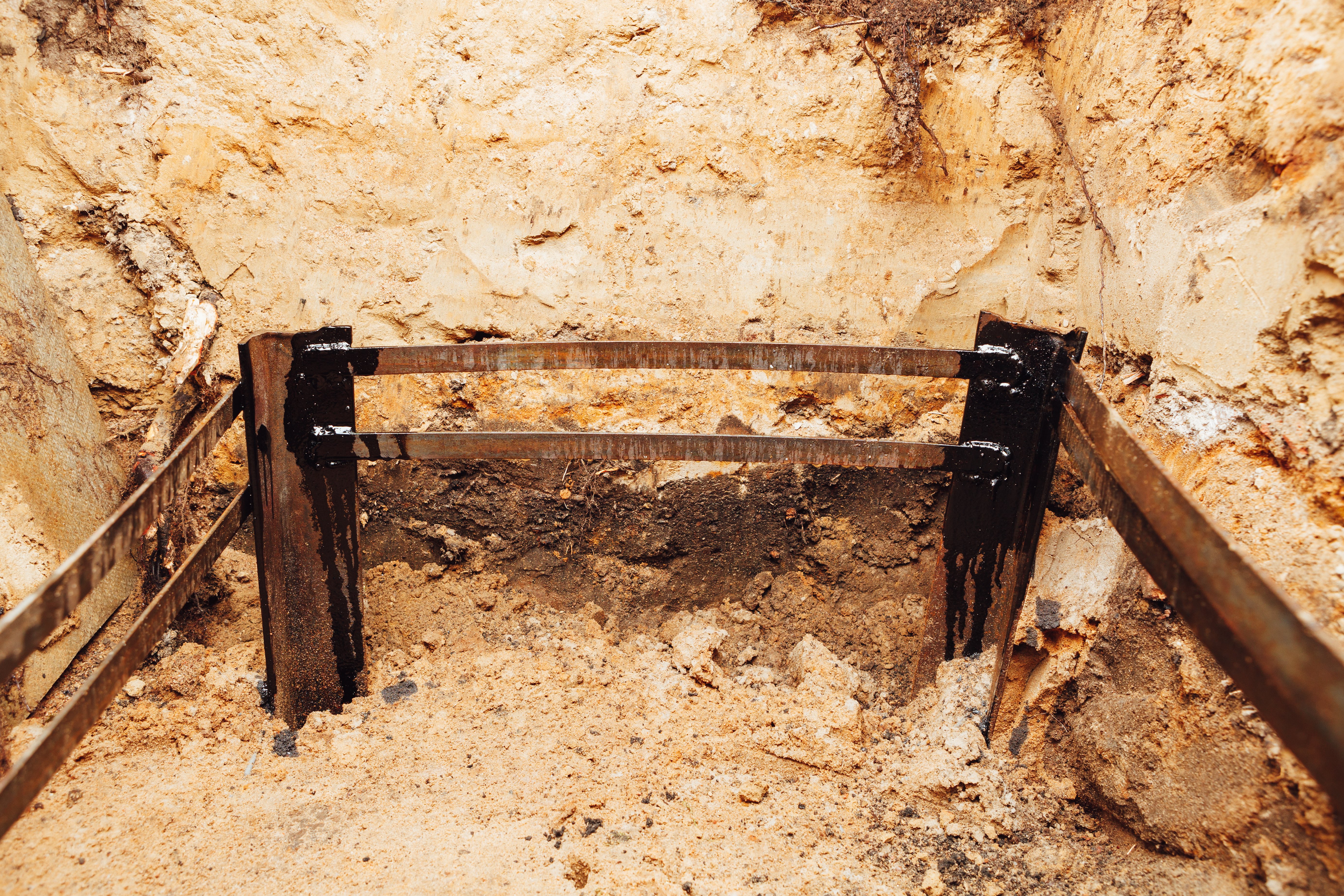
Electricity of the earthing installation, a part of the underground metal frame
Installation of electrodes in a closed circuit is more convenient in terms of space utilization, but the earthing efficiency is somewhat reduced compared to the electrodes located in a row.
The experiments have shown that mutual shielding of parallel vertical electrodes in the earth is observed at the level providing the effect on the earthing properties, at the distance less than 2.2L, where L is the electrode length. Further increase in the distance between electrodes does not provide a significant benefit. On the other side , with the distance between electrodes not more than 0.033L, the addition of new electrodes does not reduce its earthing resistance.
Conclusions
In real life, the earthing resistance varies widely depending on the season and weather conditions. Therefore, in practice, for multi-electrode vertical earthing devices, an empirical rule is often used: the distance between the electrodes should be not less than the length of one electrode. The maximum distance used so that the earthing would not be too large or expensive is the double electrode length. Since the electrode length for the multi-electrode vertical earthing is usually 3 to 5 m, the norms used in Instruction RD 34.21.122-87 are within the range of 1 to 2 electrode lengths.
However, the modern buildings have an increasingly complex structure and more metal elements are used therein. Telecoms hardware, especially cell base stations, provide very strict requirements to earthing. Therefore, it is better not to rely on empirical rules only but contact the ZANDZ.com Technical Center, where the qualified specialists will develop the design for your earthing system taking into account your particular tasks and terrain specifics where it will be implemented.
Related Articles:
 Radial Earthing Devices: Reliability at Small Depth
 Lightning Protection of Large Territories: Parks, Grounds, Plant Territories. Page 1
 Lightning Protection of Large Territories: Parks, Grounds, Plant Territories. Page 2
 Lightning Protection of Large Territories: Parks, Grounds, Plant Territories. Page 3
 Step Voltage: Dangerous Obscurity and Reliable Protection
 Nature of Electrochemical Corrosion
 Public Safety in Land Transport in case of Direct Lightning Strike
