When designing, erecting and operating electrical installations, industrial and domestic electrical equipment, as well as electric lighting systems, one of the fundamental factors in ensuring their functionality and electrical safety is precisely designed and properly carried out grounding. Basic requirements for grounding systems are contained in para. 1.7 of the Electrical Installations Code (PUE). Depending on how the respective wires, device housings, equipment or certain points of the network are connected and with what grounding structures, devices or objects they are connected, the grounding systems are divided into natural and artificial grounding.
Natural grounding is any metal objects residing in the soil, i.e. piles, pipes, fittings, and other conductive products. However, due to the fact that the electrical resistance to the spread of electric current in the soil and electric charges of these objects are difficult to control and predict, the use of natural ground during the operation of electrical equipment is prohibited. Regulatory documents allow only the use of artificial grounding, where all connections are made to specially created grounding devices.
The main standardized parameter that shows how well grounding is carried out is its resistance. The resistance to current spreading entering the soil through the ground electrode system is controlled here. The value of grounding resistance depends on the type and condition of the soil, as well as design features and the materials used to build the grounding device. The determining factor that affects the value of the ground electrode system resistance is the area of direct contact of its plates, rods, tubes and other electrodes with the soil.
Types of artificial grounding systems
The main document regulating the use of different earthing systems in Russia is PUE (paragraph 1.7) developed in accordance with the principles, classification and methods of grounding systems design approved by a special protocol of the International Electrotechnical Commission (IEC). Abbreviations of grounding systems are usually denoted by a combination of the first letters of the French words: «Terre» - gound, «Neuter» - neutral, «Isole» - to isolate, as well as the English words: «combined» and «separated».
- T - Grounding.
- N - Connection to neutral.
- I - Isolation.
- C - combined functions: combining the functional and protective neutral wires.
- S - The separate use of functional and protective neutral wires throughout the entire grid.
In the following names of artificial grounding systems, you can define the way the electrical power source (generator or transformer) is grounded by the first letter and the consumer - by the second letter. TN, TT and IT system are distinguished. The first of which, in turn, is used in three different versions: TN-C, TN-S, TN-CS. To understand the differences and the structure of the systems let's consider each of them in more detail.
1. Dead-grounded neutral systems (TN grounding systems)
This is the designation for systems in which a common dead-grounded neutral of a generator or step-down transformer is used to connect functional and protective conductors. Thus, all conductive housing parts and screens of consumers should be connected to a common neutral wire connected to this neutral. In accordance with GOST R50571.2-94, zero protective conductors of various types are also marked with the following Latin letters:
● N - Functional neutral;
● PE - Protective neutral;
● PEN - Combination of functional and protective zero conductors.
TN system built using a dead-grounded neutral is characterized by a connection of functional neutral - conductor N (neutral) - to the ground loop installed near the transformer substation. Obviously, in this system, the neutral grounding by a special compensatory device, arc suppression coil, is not used. In practice, three sub-types of the TN system are used: TN-C, TN-S and TN-CS, which differ by various ways of connecting to N and PE ground conductors.
TN-C grounding system
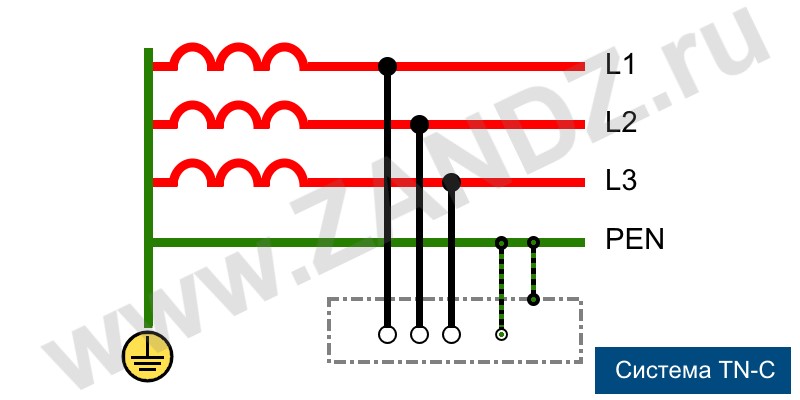
TN-C grounding system
As the letter designation suggests, TN-C system is characterized by the combination of functional and protective neutral conductors. A classical TN-C system is a traditional four-wire power supply circuit with three phases and one neutral wire. In this case, the main grounding bus is a dead-grounded neutral. All the open parts, housings and metal parts of devices that can conduct electric current should be connected to the bus using additional neutral wires.
This system has several significant drawbacks, and the most serious among them is the loss of safety functions in case of breakage or burn-off of the neutral wire. In such cases, dangerous voltages occur on the bare surfaces of instrument and equipment housings. As a separate PE protective ground conductor is not used in this system, all the connected sockets have no ground. Therefore, all the electrical equipment should be connected to neutral, i.e. the housing parts should be connected to a neutral wire.
Such type of connection provides that if a phase conductor touches the housing, a short-circuit triggers a circuit breaker. Thus, the danger of electric shock to people or fire of sparking equipment will be eliminated by the emergency power cutoff. An important limitation related to a forced neutral connection of domestic appliances powered by the TN-C system is that the use of additional potential equalization circuits in the bathrooms is prohibited, and all residents should know this.
Currently, such grounding systems can be found in houses belonging to the old housing stock. But they are also used in the street lighting networks, where the risk is minimal.
TN-S system
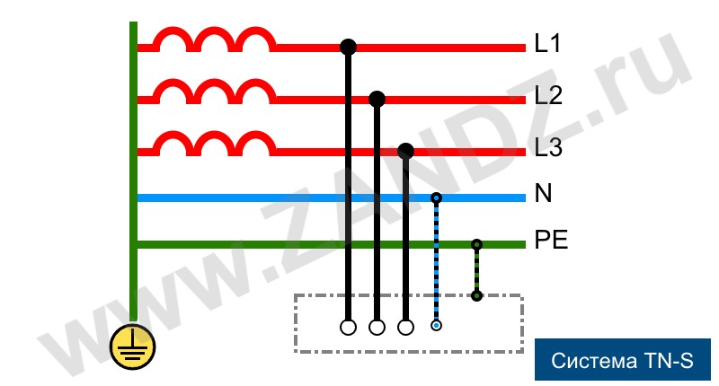
TN-S grounding system
A more progressive and safe compared to the TN-C system, TN-S system with separate neutral and protective conductors was developed and introduced in the 1930s. This solution ensures a high level of electrical safety of people and equipment. It has one, although a very significant drawback - the high cost. Since functional (N) and protective (PE) neutrals are separated at a substation itself, the three-phase voltage supply is performed via five wires; and single-phase voltage is supplied via three wires. To connect both neutral conductors at the source side, the generator's or transformer's dead-grounded neutral is used.
GOST R50571 and an updated edition of PUE provides that all critical sites, as well as energy supply buildings under construction or renovation, shall have TN-S system installed, as it provides a high level of electrical safety. Unfortunately, the wide use and implementation of the TN-S system is hindered by a high level of costs and the orientation of the Russian energy sector on the three-phase four-wire power supply.
TN-C-S system
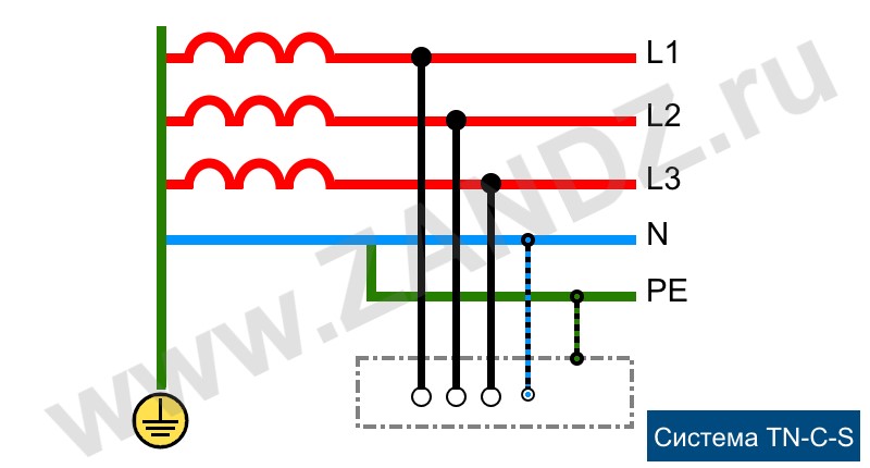
TN-C-S grounding system
In order to decrease the cost of secure but capital-intensive TN-S system with separate N and PE neutral conductors, a solution was developed that allows using its advantages with a smaller budget, slightly higher than that of the TN-C system. The principle of this connection method is that the substation supplies power using a combined PEN neutral connected to the dead-grounded neutral. At the input to the building this neutral splits into a PE protective neutral, and another conductor that works as functional N neutral on the side of the consumer.
This system has a significant drawback: in the event of breakage or burn-off of the PEN conductor in the "substation - building" section, dangerous voltages occur on the PE conductor, and, consequently, on all housing parts of electric appliances. Therefore, when a TN-C-S is used, which is quite common, regulations require the implementation of special measures to protect the PEN conductor from damage.
TT grounding system
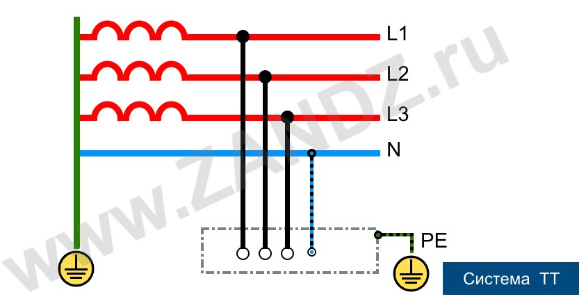
TT grounding system
When the power is supplied via overhead lines widespread in rural areas, then if the unsafe TN-C-S system is used, it is difficult to ensure the adequate protection of the PEN combined neutral conductor. TT systems are more and more used in such areas. They require the dead-grounding of the source neutral and the transfer of three-phase voltage over four wires. The fourth wire is a functional N neutral. A local, usually module-rode ground electrode system is installed on the side of the consumer, and all the protective neutral PE wires linked to the housing parts are connected to it.
Recently approved for the use in the Russian Federation, this system is rapidly spreading in the Russian provinces and is often used to power private households. In urban areas, TT is often used to power the points of street trade. With this method of grounding, circuit breakers and lightning protection are mandatory.
2. Isolated neutral system
In all systems described above, the neutral is connected to the ground, which makes them rather robust. Still they all have a number of significant drawbacks. Much more advanced and safe are systems that use an isolated neutral either absolutely not connected with the ground or grounded with the help of special equipment and devices with high resistance. For example, as in IT system. These connection methods are often used in medical facilities to power life-support equipment, in oil refineries and power plants, research laboratories with very sensitive instruments, and in other mission-critical facilities.
IT system
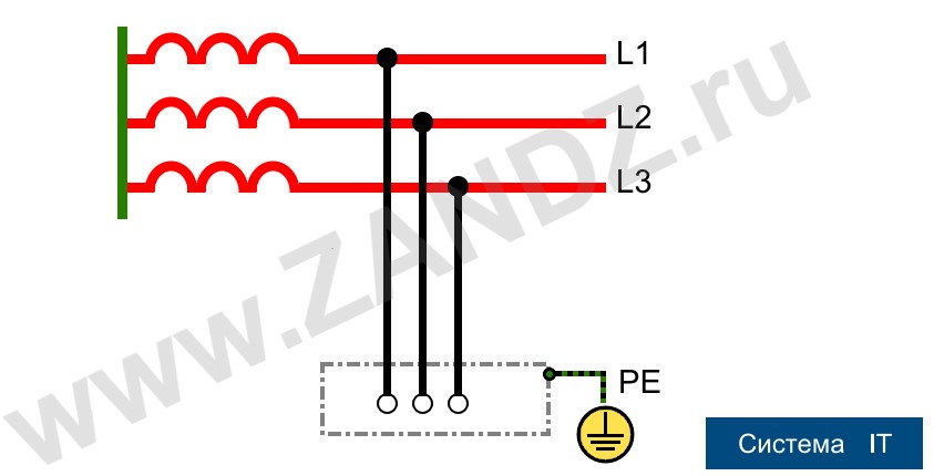
IT grounding system
This is a classical system, the main feature of which is an isolated neutral of the source - I, as well as a protective ground loop T on the side of the consumer. The voltage from the source to the consumer is transmitted over the lowest possible number of wires, and all conductive parts of the consumer equipment housings must be securely connected to the ground electrode system. There is no functional neutral conductor N on the "source - consumer" section in the IT system architecture
Reliable grounding is guaranteed security
All existing types of grounding systems are designed to ensure the reliable and safe operation of electrical appliances and equipment connected on the side of the consumer, as well as the protection people that use this equipment against electric shock. When designing and installing power supply systems with both functional and protective grounding as their integral components, the possibility of occurrence of dangerous voltages on conductive housings of devices and industrial equipment should be reduced to a minimum.
The grounding system must either remove the dangerous potential from a surface of an object or ensure the smooth operation of protective devices with a minimum of delay. In each case, technical perfection, or vice versa, the lack of perfection of a grounding system, may cost human life.
See also:
- Webinars with leading industry experts
- Everything for the calculation of grounding and lightning protection
- Useful materials: articles, recommendations, examples
Related Articles:
 Why Cannot Vertical Earthing Devices Be Installed Close to Each Other?
 Electrolytic Grounding in Permafrost Soils: Should Vertical of Horizontal Electrodes Be Used?