As with any other facilities, railway infrastructure buildings and structures may be exposed to atmospheric surges. A direct lightning strike can cause mechanical destruction, fire or explosion. If it flows near buildings, the lightning current creates an electromagnetic field, causing the failure of internal systems and creating the risk of electric shock to the staff. Electrical safety in railway transport is ensured by the integrated lightning protection of its facilities. This includes protection from the primary hazard of lightning strikes and electromagnetic pulse. Grounding is at the heart of such protective measures. It withdraws current coming to the body through the grounding portion to reduce contact voltage to a safe value.
Rail transport electrical safety regulations
The electrical safety of rail transport facilities is regulated by the requirements and norms of Federal laws, governmental decrees of the Russian Federation, normative and technical documentation of OJSC "Russian Railways" and other industries with respect to the surge protection of buildings, facilities and equipment. International regulatory framework is represented by the standards of the International Electrotechnical Commission (IEC), interstate and national standards, corporate documents by leading foreign companies, which specify the requirements of IEC standards regarding the specifics features of rail transport. The major railway infrastructure lightning protection regulations include:
- GOST R IEC 60050-195-2005. Grounding and protection against electric shock. Terms and Definitions.
- GOST R IEC 62305-1-2010 Risk management. Lightning protection. Part 1. General Principles.
- GOST R IEC 62305-2-2010 Risk management. Lightning protection. Part 2. Risk Evaluation.
- GOST R IEC 62305-3-2010 Risk management. Lightning protection. Part 3. Physical damage to the buildings (structures) and the types of hazards to human life.
- GOST R 50571.3-2009. Electrical installations of buildings. Security requirements. Protection against electric shock.
- GOST R 50571.5.54-2011. Low voltage electrical installations. Selection and installation of electrical equipment. Grounding devices, protective conductors and equipotential bonding conductors.
- GOST 12.1.030-81 Occupational safety standards system. Electrical Safety. Protective grounding, neutral wire grounding.
- GOST 2990-78 Cables, wires and cords. Voltage test methods.
- GOST R 53685-2009. Railway electrification and power supply. Terms and Definitions.
- Protecting railway automation and telemechanics systems against atmospheric and switching surge. Characteristics of impulse action on the RAT system. Temporary rules. Approved by TSSH on 22.03.2007
- Protecting the cables of rail cable communication lines against the lightning strike. Guidelines. I 84-77.St. Petersburg, GTSS 1977
- Grounding instructions for electrified railway power supply devices. Approved by the Ministry of Railways of the Russian Federation on 10.06.93, CE-191.
- Instructions for the lightning protection of buildings and structures. Departmental construction codes. RD 34.21.122-87.
- Instructions for the lightning protection of buildings, structures and industrial communications. SO 153-34.21.122-2003.
- Guidelines for the surge protection of automatic block and electric centralization devices, I-247-97, GTSS 1999
- Guidelines for the monitoring of electrical installations grounding. RD153-34.0-20.525-00. RAO "UES of Russia".
- IEC 62305 (Part 1-5). Lightning protection
- Grounding network arrangement standards. 2002.
- Electrical Consumer Installation Operation Rules. Approved by the Ministry of Energy of Russia on 13.01.2003
- Electrical installations code (PUE) Seventh edition.
- Rules of arrangement and technical operation of electrified railway contact lines. Approved on 11.12.2001, CE-868.
- Guidelines for the protection of optical communication cables from lightning strikes, 1996
- Code of practice SP 153.13130.2013 "Rail transport infrastructure. Fire safety requirements". Effective since January 1, 2013
- Federal Law of RF N 384-FZ. Technical regulation on the safety of buildings and structures.
- Federal law dated December 27, 2002 N 184-FZ. On the technical regulation.
The requirements set forth by industry documents, as well as state and interstate standards do not directly affect the regulation of surge protection at railways, as they are advisory in nature.
General requirements for grounding on railways
In order to ensure electrical safety in the railway network, grounding must be installed on all metal parts of structures and devices users can come into contact with. The resistance of grounding must not exceed values specified for this type of installations. Thus, the resistance of ground loops at traction DC substations should not exceed 0.5 ohms. The ground loop resistance at PTS powering non-traction consumers under DDA scheme should not exceed 5 ohms, and at PTS powered by longitudinal power supply lines laid on the contact line supports should not exceed 4 ohms. The intrinsic resistance of ground electrode system is not subject to standardization in cases when the allowable value of contact voltage is achieved through the use of loops and field meshes on the grounded facilities, see. paragraphs 3.5, 3.6 and 4.4 of Ground network arrangement standards.
Grounding shall be arranged using such a method that ensures switching-off the short-circuit mode. It is mandatory that standardized voltage values on grounded electrical installations are observed for the appropriate duration of protection operation, see. paragraph 3.2, 4.2 of Ground network arrangement standards.
In normal mode, it is allowed to make a gap in the ground circuit through the inclusion of safety devices, if such devices provide for the closing of the circuit in the event if a hazardous voltage occurs on the protected facilities. A safety device actuation voltage should not exceed 1200 V.
To protect facilities from surges on AC sections, grounding is made by two dead-end conductors; grounding diodes are used for this purpose on DC sections. The choice of grounding scheme for the railway infrastructure should be done on the basis of data in Table 2.4 Instructions CE-191 dated 10.06.93.
| Dead | Dead grounding with additional insulation from the ground | Through a safety device | Combined with a neutral section | Combined with additional insulation between the structures | Without rail network grounding |
| I | II | III | IV | V | VI |
| Rg>=Rnorm. | Rg>Rnorm. | Under special conditions | |||
| Application conditions | |||||
| Dead grounding is mandatory | Dead grounding is not mandatory | Structure A dead grounding is mandatory | |||
Equivalent circuits for various kinds of rail network grounding
Dead grounding is preferable from the viewpoint of electrical safety and reliability of protection against short circuit currents. Therefore, when designing lightning protection for a facility, the possibility of its arrangement following the requirements of SCB and protection against galvanic corrosion is assessed.
Railway infrastructure facilities to be grounded
According to Regulations CE-191 dated 10.06.93, the following railway infrastructure facilities shall be grounded:
- Traction substations.
- Contact line supports.
- Supply and feeder line supports.
- Contact line supports with arresters and sectional switches.
- Contact line sectioning and parallel connection points.
- Contact line switch grouping points at splicing stations.
- Autotransformer points of power supply system 2 x 25 kV.
- Negative boasting transformers and return wires.
- Reactive power compensation installations.
- Packaged transformer substations fed by the DWR system.
- Packaged transformer substations fed from 6 (10) kV line laid on contact line supports.
- Electrically heated passenger train preparation points.
- Wayside signaling devices.
- Bridges and overpasses.
- Tunnels.
- Waveguides and communication lines laid on contact line supports.
- Long air pipes of point pressurized air cleaning and pneumatic transfer systems.
- Stand-alone facilities near the electrified tracks.
- Mobile traction substations.
- Lamps, floodlight towers, overhead power and lighting lines laid on contact line supports, stand-alone lighting poles.
Let's consider the special features of grounding at some of these facilities.
Traction substation grounding
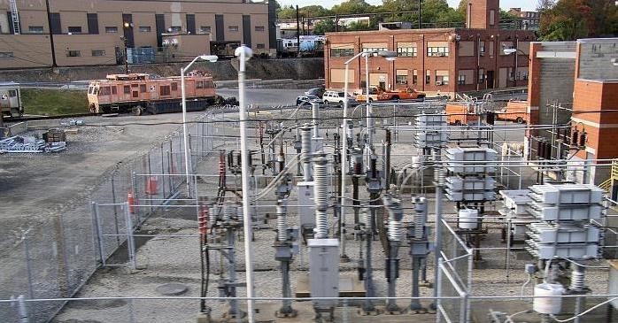
Traction substation grounding is done by connecting the switchgear of internal installations and the electric equipment of closed electrical switchgear to the grounding bus. The grounding bus is connected to the ground loop at least in two locations. The switchgear of outdoor installations and open switchgear structures are also connected to the loop.
Switchgear installations are grounded by an internal ground loop. This is performed by connecting it to an external ground loop (ground electrode system) in two points in such a way as to ensure that no permanent electrical connection to the negative power bus, feeder line and substation access rails exists.
The grounding resistance of external DC traction substations external loop must not exceed 0.5 ohms, including the resistance of natural ground electrodes. AC traction substations' ground loop performs equalization function; its own resistance is not regulated by standards. All metal equipment housings and structures at AC traction substations are grounded by connecting them to an artificial ground electrode system (ground loop).
In accordance with PUE requirements, the voltage on the ground loop shall not exceed 10 kV with respect to remote ground when current flows to the ground. If the voltage in the loop exceeds 5 kV, then measures should be considered to protect outgoing communication and remote control cables. The equipment and structures of DC traction substations to be grounded with internal and external ground loops is listed in para. 3.1.7 of Instructions CE-191 dated 10.06.93.
Grounding of contact line supports
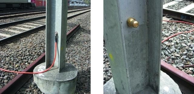
The grounding of contact line supports is performed by individual or group connection of ground wires to the traction rail network. On DC sections, the maximum length of the group ground wire shall not exceed 1200 m (2 x 600) for concrete and 600 m (2 x 300) for steel supports in case if the T-shaped connection is used, and 600 and 300 m respectively if the L-shaped connection is used.
On AC sections, the maximum length of the group ground wire shall be 400 m (2 x 200) for the T-shaped connection, and 200 m for L-shaped connection regardless of the type of support. For groups of alternating steel and concrete supports, the maximum length of a group ground wires is determined as for steel supports. The grounding of contact line supports on electrified AC sections shall be performed either as the dead grounding or through spark gaps, as set forth in para. 3.2.5 of CE-191 dated 10.06.93.
When performing the grounding of supports at DC sections, spark gaps, grounding diodes or diode-spark ground electrodes shall be installed in accordance with para. 3.2.6 of CE-191 of 10.06.93.
The points of connection between group grounding wires and the diode or diode-spark ground electrode systems with the rails should be distanced from the point of connection of contact line arrester rails for at least 100 m.
Grounding of bridges and overpasses
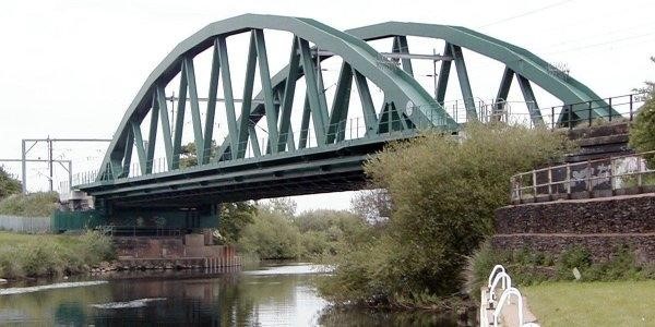
Steel bridges, overpasses, pedestrian bridges, still structures of reinforced concrete bridges and overpasses with overhead catenary, reinforcing and ground wires, or overhead line wires with a voltage higher than 1000 V mounted on them must be grounded to the traction rail line by connecting it to the bridge trusses or overhead catenary fixture elements.
The metal parts of bridges (steel and concrete ones) and other engineering structures shall be grounded with two ground wires to the traction rail line. On DC sections, a diode-spark ground electrode system shall be included in the ground loop; on AC sections, two spark gaps, one in each ground wire, shall be included. Steel and concrete supports installed on bridges and catenary mounting elements shall have a dead connection with the structure of steel bridge or the grounding loop of a reinforced concrete bridge.
Protection against primary hazards of lightning strikes
In order to choose an optimal solution for a lightning protection system, protection methods for railway infrastructure should be selected at the stage of their design.
A reliable lightning protection at a facility is ensured by the arrangement of the protective grounding for the whole building or structure with consideration all related structures.
Any non-insulated lightning protection system should have at least two down conductors equally spaced along the perimeter of the structure, for the passage of the lightning current from the lightning rods to the ground electrode system. For effective lightning protection, straightly laid down conductors must have a minimum length.
Elements of buildings that meet the requirements of the Regulations SO 153-34.21.122-2003 are used as a natural down conductors.
The artificial grounding of facilities is performed with grounding electrodes using different types of their arrangement. Type A configuration implies the connection of vertical or horizontal electrodes to each of the down connectors.
Type B configuration includes a grounding conductor of the foundation or an external loop that remains in contact with the soil almost throughout its entire length. This type of protection is recommended for the grounding of structures and building of telecommunication, railway automation and remote control facilities with a laying depth of not less than 0.5 m when located at a distance of 1 m from the external walls. Additional ground electrodes are mounted at regular intervals in the connection points of down conductors to the loop.
Any underground metal structures, as well as interconnected concrete reinforcement bars, can be used as grounding electrodes, subject to the continuous flow of electric current through them and the possibility to measure their spreading resistance.
IEC 62305 standard determines the minimum allowable size and cross-section of ground conductors made of most commonly used materials based on their corrosion and mechanical resistance.
In accordance with IEC 62305-3, the lightning protection loop should have a resistance of less than 10 ohms. The grounding of telecommunication units and buildings of ESB posts often requires a lower resistance value, so it can be also used as lightning protection grounding.
For the effective lightning protection of railway infrastructure, grounding devices of buildings and structures should be combined with the protective grounding of the related telecommunication facilities, electrical installations and RAT systems. In the event if the grounding electrode systems are separated because of technological requirements, they should be combined into a single system by the equalization of potentials.
Protection against secondary hazards of lightning strikes
In addition to a possible direct lightning strike into the protected object, its internal systems may be subject to the secondary hazardous effects due to the occurrence of a difference in potentials.
The protection of buildings and telecommunication systems, equipment and staff inside them from primary and secondary hazards of lightning is provided by an internal LPS lightning protection system by the equalization of potentials using the following:
- ground conductors - in cases when natural conductors do not ensure the continuity of current flow;
- SPD - in cases when connection with LPS conductors is impossible.
To protect electrical installations up to 1 kV from a surge, buildings are equipped with a common main grounding bus by connecting several conductors available for the connection. There shall be at least two such conductors at different points of the ground electrode system. Such conductors are usually made of steel tapes 4x40 mm. They shall comply with the requirements of GOST R 50571.5.54-2013 and sustain the flow of a part of the lightning current.
The bus is placed near the power supply source of the facility or the power cable input point, to ensure access to the connection points for visual inspection. At facilities with multiple input points, the bus is installed for each input device.
The main grounding bus allows equalizing potentials between the conductive elements located in the zone of conductors' coverage; it also functions as a PE protective conductor for electrical installations. Using the bus as a protective conductor N is not allowed.
The lightning protection of power cables is provided by SPDs by connecting ground conductors from these devices via the potential equalization bus to the main grounding bar using the shortest route. In such cases, copper ground conductors are used; they are laid in such a manner as to ensure their minimal electromagnetic interference with other circuits.
A ring grounding device can be connected to the main grounding bus in one point only - on one side of the structure. Connecting the grounding conductor directly to the grounding device bypassing the main grounding bus is not allowed. The resistance of ground electrode system is measured only when communications are disconnected from the bus.
Conclusion
The value of grounding for electrical safety on the rail transport is hard to overestimate. Errors in the grounding usually lead to the dynamic and thermal destruction of facilities, as well as equipment and internal systems failure, which is extremely dangerous and can lead to serious consequences. Therefore, disregarding the rules regulating the arrangement of lightning protection and grounding is not acceptable. The grounding of rail infrastructure facilities should be made according to the relevant regulations and in strict compliance with the requirements contained therein.
See also:
- Lightning protection and grounding solutions for large facilities
- Lightning protection of oil and gas facilities
- Webinars for designers
- Surge protection
- Calculation of grounding
Related Articles:
 Lightning Protection Design for a Railroad Terminal and Station
