![]()
... from the book "Grounding: answers to questions"
...republication of the articles placed on" Habrahabr"
My story will consist of three parts.
Part 1. Grounding
(general information, terms and definitions)
Part 2. Traditional construction methods of grounding devices
(description, calculation, installation)
Part 3. Modern construction methods of grounding devices
(description, calculation, installation)
In the first part, I will describe the terminology, the basic types of grounding (purpose) and grounding requirements.
In the second part I will tell a story about traditional solutions used at the construction of grounding devices, listing the advantages and disadvantages of these solutions.
The third part will continue the second one in some way. It will contain the description of new technologies used at the construction of grounding devices. Like in the second part with the list of advantages and disadvantages of these technologies.
If the reader possesses theoretical knowledge and is only interested in practical implementation - it is better to skip the first part and start reading the second part.
If the reader has the necessary knowledge and wants to learn information only about novelties - it is better to skip the first two parts and go directly to reading the third.
My focus on the described methods and solutions is somewhat one-sided. I ask the reader to understand that I am not setting my material forth as the comprehensive objective work and express my point of view and my experience in it. Some part of the text is a compromise between the accuracy and the desire to explain in "human language", that is why, there can be some simplification that could "shock the ear" of a tech-savvy reader.
Part 1. Grounding

In this part I will tell about the terminology, about the basic types of grounding and the qualitative characteristics of grounding devices.
B. Purpose (types) of grounding
B1. Working (functional) grounding
B2. Protective grounding
B2.1. Grounding as a part of external lightning protection
B2.2. Grounding as a part of surge protection system (SPD)
B2.3. Grounding as a part of power supply network
C. Grounding quality. Grounding resistance.
C1. Factors affecting quality of grounding
C1.1. Contact area of ground electrode system with the ground
C1.2. Electrical soil resistance (specific)
C2. Existing norms of ground resistance
C3. Calculation of ground resistance
A. Terms and definitions
To avoid confusion and misunderstanding further in the story - I'll start with this point. I will give the fixed definitions from the current document "Electrical Installation code (EIC)" in the latest edition (chapter 1.7 as revised in the seventh edition).
And I will try to "translate" these definitions into the "simple" language.
Grounding - Intentional electrical connection of some network point, electrical installation or equipment with the grounding device (EIC 1.7.28).
The soil is the environment able to "absorb" electric current. It is also a "common" point in the electrical circuit, with respect to which the signal is perceived.
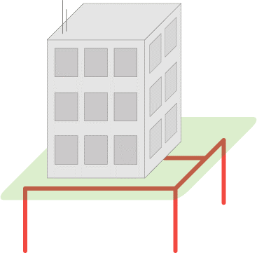
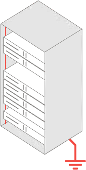
Grounding device is a set of a ground electrode / electrodes and grounding conductors (EIC 1.7.19).
This device / circuit consisting of a ground electrode and grounding conductor, connecting this ground electrode with the grounding part of the network, electric installation or equipment. It can be distributed, ie, consist of several mutually remote ground electrodes.
In the figure it is shown in thick red lines:
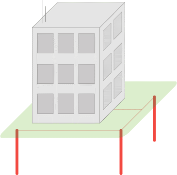
Ground electrode system is a conducting a part or a complex of interconnected conductive parts electrically connected with the ground (EIC 1.7.15).
Conductive part - a metal (conducting) element / electrode of ay profile and structure (pin, tube, strip, plate, mesh, bucket :-)) etc) located in the ground and through which the electric current "flows" from the installation. Configuration of the ground electrode (quantity, length, location of electrodes) depends on the requirements and soil's ability "to absorb" electrical current running / "flowing down" from the power plant through these electrodes.
Additional information is available on a separate page "Ground electrode system".
In the figure it is shown by thick red lines:

Ground resistance - ratio of the voltage on the grounding device to the current flowing from the ground electrode into the ground (EIC 1.7.26).
Ground resistance - the main indicator of the grounding device, which determines its ability to perform its functions and determines its quality in general. Ground resistance depends on the area of electrical contact of the ground electrode system (grounding electrodes) with the ground ( "drainage" of the current), and the electrical soil resistance in which this ground electrode system is mounted (current "absorption").
Additional information is available on a separate page "Ground resistance".
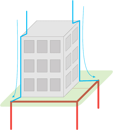
Grounding electrode (electrode of the ground electrode system) - is a conducting part electrically connected with the local ground (GOST R 50571.21-2000 paragraph 3.21.)
Let me repeat myself: any metal (conducting) element of any type or construction may act as a conductive part (pin, tube, tape, plate, mesh, bucket :-) etc) located in the ground and through which the electric current "flows" into it from the electric plant.
In the figure they are shown by thick red lines:
Further definitions are not found or are not described precisely enough in the standards and norms, thus having only my description.
Grounding contour - "peoples" name of the ground electrode system or grounding device consisting of multiple ground electrodes (group of electrodes), connected to each other and mounted around the object around its perimeter / contour.
Additional information is available on a separate page "Grounding contour".
On the picture, the object is marked as a grey square in the center, and the grounding contour by thick red lines:
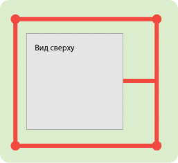
Вид сверху – top plan view
The electrical soil resistance is a parameter that defines the level of soil "conductivity" as a conductor, that is, how well the electric current will flow in such an environment from the ground electrode. It is a measured value, which depends on the soil composition, its size and density of its particles, humidity and temperature, concentration of soluble chemicals in it (salts, acid and alkaline residuals).
Additional information is available on a separate page "Soil resistivity".
B. Purpose (types) of grounding
Grounding is divided into two main types according to the role performed - working (functional) and protective. Also different sources contain additional types, such as the "tool", "measuring", "control", "radio" grounding.
B1. Working (functional) grounding
It is grounding of a point or points of the current-carrying parts of electrical installations performed for the operation of the electric installation (not for purposes of electrical safety) (EIC 1.7.30).
Working grounding (electrical contact with the ground) is used for the normal functioning of electrical systems or equipment, ie for their operation in an ORDINARY mode.
B2. Protective grounding
It is grounding, performed for the sake of to electrical safety (EIC 1.7.29).
Protective grounding protects electrical installations and equipment, as well as protecting people from impacts of hazardous voltages and currents that may arise in cases of failure, improper operation of equipment (ie in an EMERGENCY mode) and lightning discharges. Protective grounding is also used to protect equipment from interferences due to switching in the mains supply and interface circuits, as well as electromagnetic interference, induced by the equipment working near. We can study the purpose of grounding in more detail in two examples:
- as a part of external lightning protection system in the form of the grounded lightning rod
- as a part of overvoltage protection system
- as a part of the object's electricity mains
B2.1. Grounding as a part of lightning protection
Lightning is a discharge or in other words "breakdown", arising FROM the cloud TO the ground, at the accumulation of a discharge of a critical value in the cloud (relative to the ground). Example of this phenomenon but of a smaller scale is a "breakdown" (wiki) in the condenser and a gas discharge (wiki) in the lamp.
Air is an environment with very high resistance (dielectric), but the discharge overcomes it, because it has greater power. Discharge path passes along the sections of the least resistance, such as water drops in the air and trees. This explains the root like lightning structure in the air and frequent lightning strike into the trees and buildings (they have lower resistance than the air in the gap).
When striking the roof of the building, the lightning continues its way to the ground also selecting parts with the lowest resistance: wet walls, wires, pipes, electric appliances - thus presenting danger to humans and equipment in the building.
Lightning protection is designed to divert lightning from the protected building / facility. Lightning discharge going on the path of least resistance gets into the metal lightning rod over the object, then over the metal lightning rods located outside the object (for example, on the walls), descends to the ground, where it diverges in it (let me remind: soil is an environment with the property to "absorb " electrical current).
To make lightning protection "attractive" for the lightning, as well as to avoid spreading of lightning currents from lightning protection components (receiver and drainages) inside the object, its connection with the ground is made through the ground electrode having a low ground resistance.
Grounding in such a system is a must, because it ensures a complete and rapid transition of lightning currents into the ground, preventing them from spreading over the object.
Additional information is available on a separate page "Lightning protection and grounding".
B2.2. Grounding as a part of surge protection system (SPD)
SPD is designed to protect electronic equipment from the charge accumulated on any section of the line / network as a result of exposure to electromagnetic fields (EMF) induced by a neighbouring powerful electrical installation (or high-voltage line) or EMF arising under a close (up to hundreds of meters) lightning discharge.
A striking example of this phenomenon is accumulation of the charge on a copper cable of a house network or "hanging wires" between buildings during a thunderstorm. At some point, the devices connected to the cable (computer network card or switch port), can not stand the "size" of the accumulated charge and an electric breakdown occurs inside this device, which destroys it (broadly).
An SPD is put before the equipment to "bleed off" the accumulated charge simultaneously with the "loading" on the line.
A classic SPD is a gas discharger (wiki), designed for a certain charge "threshold" that is less than the "safety margin" of the protected equipment. One of the electrodes of this discharger is grounded, and the other is connected to one of the line / cable wires.
Upon reaching this threshold, there happens a discharge in the discharger :-) between the electrodes. As a result, the accumulated charge is drained to the ground (through the grounding).
.png)
Линия - прибор – Line - instrument
Like in lightning protection - grounding in such a system is an indispensable element because it provides timely and guaranteed occurrence of a discharge in the SPD, not allowing the excess charge on the line above the safe level for the protected equipment.
B2.3. Grounding as a part of power supply network
The third example of the protective role of grounding is to ensure safety of humans and electrical equipment during breakdowns / emergencies.
The easiest way to describe such a failure is by the closure of a phase wire of the electricity mains on the device body (closure in the power supply unit or in the heater via the aquatic environment). Having touched such a device, the human will create an additional electrical circuit through which the current will run causing damage of the body organs - especially nervous system and heart.
To eliminate such effects connection of the body frames with grounding is used (to drain emergency currents into the ground) and automatic safety devices in a fraction, that disable the current in case of emergency in a split second. For example, grounding of all body frames, cabinets and frames of telecommunications equipment.
C. Grounding quality. Grounding resistance.
For proper performance of its functions, the grounding should have certain parameters / characteristics. One of the main characteristics that define the grounding quality is the current spreading resistance (ground resistance), which determines the ability of the ground electrode system (grounding electrodes) to transmit currents, coming to it from the equipment to the ground.
This resistance has a finite value and in the ideal case presents itself a zero value, which means absence of any resistance by passing the "harmful" currents (this ensures their FULL absorption by the ground).
Additional information is available on a separate page "Ground resistance".
C1. Factors affecting quality of grounding
Resistance mainly depends on two conditions:
- square (S) of the electrical contact of the ground electrode system with the ground
- electrical resistance (R) of the ground in which the electrodes are placed
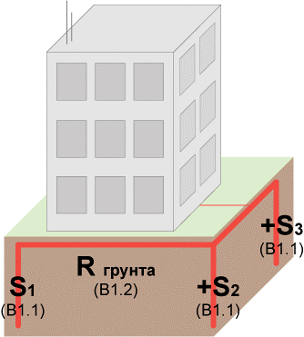
R грунта –R of soil
C1.1. Contact area of ground electrode system with the ground
The larger is the contact area of the ground electrode system with the ground, the more is the square for the current transition from the ground electrode system into the ground (the more favourable conditions are formed for the current transition into the ground). This can be compared with the behaviour of a vehicle wheel when turning. A narrow tire has a small contact area with the asphalt and can easily start to slide on it, "sending" the car into a skid. Wide tires, and even a little bit deflated, has much greater area of contact with the asphalt, thus ensuring a secure bond with it and, consequently, a reliable movement control.
It is possible to enlarge the contact area of the ground electrode system with the ground by either increasing the number of electrodes, connecting them together (adding squares of multiple electrodes) or by increasing the size of the electrodes. At the application of vertical ground electrodes, the latter method is very effective if the underground soil layers have a lower electrical resistance than the upper ones.
C1.2. Electrical soil resistance (specific)
Let me remind you: this is the value that determines how well the soil conducts the current through itself. The lower is the resistance of the soil, the better / easier it will "absorb" current from the ground electrode system.
Examples of highly conductive soils is salt marshes or wetland clay. The ideal natural environment for current transmission is seawater. An example of a "bad" soil for grounding is dry sand.
(If you're curious, you can see chart of values of soil resistivity, used at the calculation of grounding devices).
Coming back to the first factor and the method of reducing ground resistance in the form of increasing the depth of the electrode, it can be said, that in practice more than in 70% of cases, the soil at the depth of 5 m has a several times lower electrical resistance than the surface, due to higher moisture and density . There are often ground waters, which provide very low ground resistance. Grounding in these cases is of a very high quality and reliable.
C2. Existing norms of ground resistance
Since the ideal (zero resistance to spreading) cannot be achieved, all electrical and electronic devices are based on some normalized values of ground resistance, such as 0.5, 2, 4, 8, 10, 30 or more ohms.
For your guidance, I will give the following values:
- for 110 kV substation, current spreading resistance should be not more than 0.5 Ohm (EIC 1.7.90)
- at the connection of telecommunications equipment, the grounding should generally have a resistance of not more than 2 or 4 ohms
- for a reliable operation of gas dischargers in protective devices of overhead lines (eg, local network based on copper cable or RF cable) grounding resistance to which they (dischargers) are connected should be not more than 2 Ohms. There are exemplars with the requirement of 4 Ohms.
- the current source (eg transformer substation) should have the grounding resistance of not more than 4 ohms at the line voltage of 380 V of a three-phase power supply or 220 V of a single-phase power supply (EIC 1.7.101)
- grounding used to connect lightning rods should have the resistance of not more than 10 ohms (RD 34.21.122-87, p. 8)
- for single-family houses connected to the electric mains of 220 Volt / 380 Volt:
- using a TN-C-S system, it is necessary to have local grounding with the recommended resistance not more than 30 ohms (guided by the EIC E 1.7.103)
- when using the TT system (isolating grounding from the neutral of the power supply) and using a residual current device (RCD) with an operative current of 100 mA it is necessary to have a local ground resistance not more than 500 ohms (EIC 1.7.59)
C3. Calculation of ground resistance
For a successful design of a grounding device that has the necessary ground resistance as a rule typical configurations of a ground electrode and base formula for calculations are used.
The configuration of the ground electrode is usually chosen by an engineer on the basis of his experience and possibility of its (configuration's) application on a particular object.
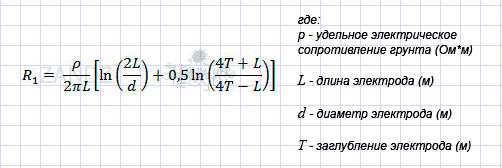
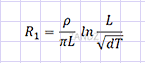
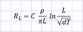
Selection of calculation formula depends on the chosen configuration of the ground electrode. The formulas themselves contain parameters of this configuration (for example, number of grounding electrodes, their length, thickness) and soil parameters of a particular object where the ground electrode will be placed. For example, for a single vertical electrode, this formula will be as follows:

Where:
P – удельное электрическое сопротивление грунта (Ом*м) – soil electric resistivity (Ohm*m)
L – длина электрода (м) – electrode length (m)
d- диаметр электрода (м) –electrode diameter (m)
T-заглубление электрода (м) – Electrode burial (m)
The accuracy of the calculation is usually low and also depends on the soil - in practice the difference of practical results is met in almost 100% of cases. This is due to its (ground) high inhomogeneity: it is changed not only the depth, but also by the square- forming a three-dimensional structure. The existing formula for calculating grounding parameters can hardly handle the one-dimensional inhomogeneity of the soil, and in the calculation in the three-dimensional structure is associated with the huge processing power and requires very highly qualification of the operator.
Furthermore, to create an exact soil maps it is needed to hold a large volume of geological works (for example, for the area of 10 x 10 meters, it is necessary to make and analyze about 100 pits up to 10 meters long), which causes a significant increase of the project cost and is often impossible.
In view of this, a calculation is almost always a mandatory, but indicative measure and is usually held on the principle of achieving ground resistance with the value of "not more than". The average values of ground resistivity, or their greatest values are put into the formula. This provides a "safety margin" and on practice is expressed in obviously lower (lower means better) values of ground resistance than it was expected at the design.
Additional information is available on a separate page "Ground electrode system".
Construction of ground electrode systems
Usually, vertical ground electrodes are applied at the construction of ground electrode systems. This is due to the fact that it is difficult to bury the horizontal electrodes to a great depth, and with a shallow depth of such electrodes - their ground resistance increases significantly (deterioration of the main characteristics) in winter time due to freezing of the top soil layer, resulting in a large increase of its electrical resistivity.
Steel pipes, rods / rods, angles, and other standard rolled products of a long length (more than 1 meter) at relatively small cross-section dimensions are almost always used as vertical electrodes. This choice is associated with the possibility of an easy burial of such elements into the ground as opposed to, for example, a flat sheet.
Read more about construction in the next sections.
Part 2. Traditional construction methods of grounding devices (description, calculation, installation)
.png)
Part 1. Grounding
(general information, terms and definitions)
Part 2. Traditional construction methods of grounding devices
(description, calculation, installation)
Part 3. Modern construction methods of grounding devices
(description, calculation, installation)
In this article, I will tell about traditional / classical methods of construction of ground electrode systems used approximately since the beginning of the twentieth century.
D. Main construction methods
D1. Several short electrodes ( "angle and sledgehammer")
D1.1. Solution features
D1.1.1. Soil freezing in winter
D1.1.2. Mutual "screening" / "shadowing" of the electrodes
D1.2. Calculation of the resulting ground resistance and the required number of ground electrodes
D1.3. Assembling
D1.4. Advantages and disadvantages
D1.5. Reduction of the number of electrodes
D2. Single depth electrode ( "casing pipe")
D2.1. Solution features
D2.2. Calculation of the obtained ground resistance
D2.3. Assembling
D2.4. Advantages and disadvantages
D. Main construction methods
In the last part I focused on the overall approach.
Usually, vertical ground electrodes are applied at the construction of ground electrode systems. This is due to the fact that it is difficult to bury the horizontal electrodes to a great depth, and with a shallow depth of such electrodes - their ground resistance increases significantly (deterioration of the main characteristics) in winter time due to freezing of the top soil layer, resulting in a large increase of its electrical resistivity. Steel pipes, rods / rods, angles, and other standard rolled products of a long length (more than 1 meter) at relatively small cross-section dimensions are almost always used as vertical electrodes. This choice is associated with the possibility of an easy burial of such elements into the ground as opposed to, for example, a flat sheet.
There are two main traditional approaches / solutions for building ground electrodes. Both are based on the use of vertical grounding electrodes
D1. Several short electrodes ( "angle and sledgehammer")
At such an approach, small (2-3 meters) steel angles / rods are used as grounding electrodes. To create ground electrode system they are joined together near the soil surface with a steel tape by welding it to these elements with electric or gas welding.
Deepening of the electrodes into the ground is held by a banal hammering with a sledgehammer, which is in the hands of a physically strong and sturdy installer. Therefore, such a solution is widely used under the code name "angle and sledgehammer."
Large contact area of the ground electrode with the ground (here is what I mean) is reached by a large number of electrodes (multi-electrode ground electrode system). It is very hard to increase the depth of the electrodes (an alternative way of increasing the contact area), because with the increase of the depth, the frictional force between the mounted electrode and the ground increases, and weight of the sledgehammer and energy of the installer have their limit.
When selecting angles / rods and other suitable rolled stock it is necessary to consider their corrosion resistance and the ability to transmit large magnitude currents during some period of time without melting.
Minimum permitted cross sectional dimensions (cross-sections) of grounding electrodes are described in chart 1.7.4 of the EIC, but in the recent few years the amended and supplemented values from chart 1 of the technical memo 11 from 2006 of the association "Roselectromontazh" are used (sources).
In particular:
- for an angle or rectangular profile (tape) of black steel the cross-section shall be at least 150 mm2 with a minimum wall thickness of 5 mm
- for a round rod made of black steel, the minimum diameter must be 18 mm
- for structural tubing shape made of black steel, the minimum diameter should be 32 mm with a minimum wall thickness of at least 3.5 mm
D1.1. Solution features
Increasing the number of electrodes it is necessary to consider some features.
D1.1.1. Soil freezing in winter
In winter, due to soil freezing to the depths in which half of the length of the electrodes is buried (which is up to 2 meters) grounding resistance of such a ground electrode system increases. To compensate this increase (to keep a satisfactory quality of the grounding) the ground electrode system is carried out with a sufficient "margin" of electrodes. For example, for three-meter electrodes a double increase of their number is required.
D1.1.2. Mutual "screening" / "shadowing" of the electrodes
In addition, the increase in the number of electrodes must be compensated by an increase in the number of electrodes itself :-) This negative aspect of the so-called "screening" / "shading" occurs when using multiple ground electrodes, and does not allow the closely located electrodes to fully "dissipate" the current into the surrounding soil. Is expressed in the form of a coefficient of using ground electrode conductivity.
For example: ten electrodes 3 meters deep each arranged in a line at the distance of 3 meters (that is, distance = its depth) from each one give 60% of their maximum efficiency. Ten of these electrodes placed at the distance of 6 meters (that is, distance = double depth) from each other give 75% of their maximum efficiency. One hundred percent efficiency is achieved by distancing the electrodes to about 30 meters (10 of their depths), which in practice is never used for the sake of adequate compactness and installation cost of the grounding device.
D1.2. Calculation of the resulting ground resistance and the required number of ground electrodes
I will describe the calculations on the example of three-meter electrodes most frequently used for such a method in the form of a steel equal angle with the width of the shelf 50 mm, mounted at the distance 3m from each other in a pit 0.5 meters deep ( there is an explanation "why so" in p. D1.3.). I will describe the calThe soil, in which these electrodes will be installed, will be clay loam, common in Russia, with the resistivity of 100 Ohm * m.
Calculations are not complicated and are carried out in 3 stages.
The resulting ground resistance
Stage 1. First we need to calculate grounding resistance of one ground electrode. Ground resistance of a single vertical ground electrode is calculated as follows:
Where:
P – удельное электрическое сопротивление грунта (Ом*м) – soil electric resistivity (Ohm*m)
L – длина электрода (м) – electrode length (m)
d- диаметр электрода (м) –electrode diameter (m)
T-заглубление электрода (м) – Electrode burial (m)
R1 will be 27.8 Ohm (When p = 100 Ohm * m, L = 3 m, d = 0.05 m (50 mm; for flat electrodes their width is understood as the diameter), T = 2 m (T - distance from the top of the upper ground level to the middle of the buried electrode)).
Stage 2. The total resistance of several electrodes in ideal conditions will be less than one ground electrode resistance as many times as how many are the electrodes.
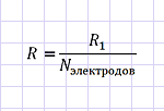
N электродов – N electrodes
The total resistance for the ten electrodes will be 10 times less and will be about 2.78 Ohm.
Stage 3. "Compensations".
Seasonal coefficient (increase of ground resistance in the frozen ground in winter) for such electrodes will be equal to 2 (where this comes from ). The electrode conductivity coefficient will be equal to 0.6, since the distance between the electrodes will be 3 meters (i.e., equal to the depth of the electrode), and their number - 10 pieces (where this comes from ).
Both coefficients increase ground resistance
К сезонный – K seasonal
К использования – K of use
N электродов – N electrodes
The resulting total ground resistance of the indicated 10 electrodes will be equal to 5.56 Ohm in summer and 9.27 Ohm in winter.
The required number of ground electrodes
let's imagine that our task is to ground telecommunication equipment and for that it is necessary to receive the grounding resistance of not more than 4 Ohm.
Stage 1. Everything repeats. We calculate ground resistance of one / single ground electrode.
where:p- soil electrical resistivity (Ohm*m)
L - electrode length (m)
d- electrode diameter (m)
T - electrode depth (m)

Where:
P – удельное электрическое сопротивление грунта (Ом*м) – soil electric resistivity (Ohm*m)
L – длина электрода (м) – electrode length (m)
d- диаметр электрода (м) –electrode diameter (m)
T-заглубление электрода (м) – Electrode burial (m)
R1 will be 27.8 Ohm.
Stage 2. The number of electrodes in ideal conditions directly depends on the required ground resistance with the round up to the greater side ( "ceiling").
N электродов – N electrodes
In order to achieve 4-ohm, the number of electrodes will be 7 pieces (round up of 6.95).
Stage 3. "Compensations".
N электродов – N electrodes
К сезонный – K seasonal
К использования – K of use
The final necessary amount of the indicated ground electrodes will be equal to 28 pieces (round up of 27.8).Coincidence with the ground resistance of one electrode is accidental.
D1.3. Assembling
Assembling of a multi-electrode ground electrode system described above looks like this.
- From the point of input of the ground conductor inside the building /around the object perimeter / contour of the building along the walls at the distance of 1 meter there is a pit 84 meters long (28 electrodes 3 meters deep) 0.5-0.7 meters deep.
- Pre-sharpened on the lower side (with the angle grinder) steel corners or sections of fittings 3 meters long in the amount of 28 meters are hammered into this pit at the distance of at least 3 meters from each other with a sledgehammer.
- After hammering all the electrodes - a ground conductor from the input into the building (where the electrical panel is located) to the furthest electrode is being put into the pit. Usually a steel tape 4 * 50 mm acts as a conductor in such a method.
- The tape is in a quality manner (!) welded to the electrodes with a long seam.
- The welding point is covered with the layer of bitumen or anticorrosive paint as it has a tendency to rapid corrosion in the ground.
- The pit is filled up.
- Outside or inside the building, the transition from the steel tape to a copper wire connected to the switchboard, is made. For low power it is usually done like this:
Deepening to 0.5-0.7 meters (pitch) is necessary for a mechanical and weather insulation of the conductor (tape), and tops of the electrodes. For example, to avoid damaging them while digging the soil for the flower garden and to prevent steel getting wet in the rain (it allows to reduce its corrosion and thus increase its service life).
The mutual distance between the electrodes of at least 3 meters is some measure of counteracting the effect of "shielding" / "shadowing" of the electrodes from each other.
The use of welding for connecting elements made of black steel is highly recommended by EIC (n 1.7.139.).
Materials used:
- steel corner 50 mm wide and with the wall thickness of 5 mm = 84 meters
- or segments of steel smooth reinforcement 18 mm in diameter = 84 m
- steel tape 4 * 50 mm = about 85 m
- bitumen or anti-corrosive paint
Used tools:
- shovel
- heavy sledgehammer (4-5 kg)
- welding machine
used resources:
- strong and sturdy installer
- installer, possessing welding skills
D1.4. Advantages and disadvantages
Advantages:
- simplicity
- low cost of materials and installation
- availability of materials and installation
Disadvantages:
- high cost of delivery of the material to the facility (they cannot be put in a passenger car due to the sizes and weight of the materials)
- need to apply a large amount of brute force (to dig a pit, work with a sledgehammer)
- welding is required, and therefore- a welding machine and a person with welding skills. The situation is exacerbated by the absence of electricity at the facility.
- large square, occupied by the ground electrode: often several tens of meters around the building (ten 3-meter electrodes should be placed in a pit 27 meters long)
- short service life of the electrodes of 5-15 years (especially in soils with high ground waters). increase of cross-section dimensions (steel thickness) is accompanied by the increased assembling complexity.
- inconvenient assembling, because even when using 2-meter electrodes at the beginning of hammering it is necessary to stand on some sort of a bench / stairs and "wave with a sledgehammer" standing on it.
- impossible assembling in rocky soil
D1.5. Reduction of the number of electrodes
Sometimes, together with that decision, the method of a radical reduction of soil electrical resistance, which allows to reduce the number of grounding electrodes 2-3 times while maintaining the resulting ground resistance. In other words - this method allows to significantly reduce ground resistance. This is about soil salinization in the point where the electrodes are located by adding of a large amount of salt NaCl into it (on average - 5 kg per meter of the pit length, in which the assembly is held). When it is dissolved in the ground (desalination(wiki)) the concentration of ions involved in the charge transfer dramatically increases, and thus reduces its (ground's) electrical resistance.
With the undeniable positive virtue of this method, as well as its simplicity and cheapness - it has two huge shortages which threaten with the recovery of the ground electrode virtually "from scratch":
- at the expense of leaching out of salts from the ground (rain, spring melting of snow), ion concentration falls to a natural level in 1-3 years
- salt causes severe steel corrosion, destroying the electrodes and the ground conductor in 2-3 years
D2. Single depth electrode ( "casing pipe")
D2.1. Solution features
D2.2. Calculation of the obtained ground resistance
D2.3. Assembling
D2.4. Advantages and disadvantages
In this approach, a depth electrode is the ground electrode (usually single) in the form of a steel pipe located in the drilled hole in the ground. Drilling and placement in the hole of the pipe is done with a special machine - drilling rig (usually on the basis of a lorry).
Large contact area of the ground electrode with the ground (here is what I mean) is achieved by a great length (or rather, depth) of the electrode. Moreover, by achieving deep soil layers, in most cases having a lower specific electrical resistance, such a method is more efficient (smaller ground resistance) than the first one - with the same total length of the electrodes.
D2.1. Solution features
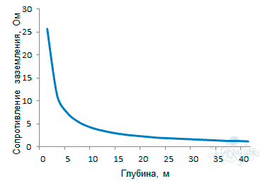
By increasing the depth of the electrode it is necessary to keep in mind that in a homogeneous soil ground resistance does not decrease proportionally to this increase (greater depth -> lower resistance reduction).
-2.png)
Сопротивление заземления, Ом – Ground resistance, Ohm
Глубина, м - Depth, m
Therefore, at the absence of soil layers with a lower specific electric resistance at the depth, it is necessary to consider the question of an increase of the number of electrodes, rather than increasing depth of a single electrode. The cost and installation of additional electrodes, and the availability of space to accommodate them will influence the resolution of this question.
But let me remind (original): ... in practice more than in 70% of cases, the soil at the depth of 5 meters has several times lower electrical resistivity than that of the surface, due to the higher moisture content and density.
D2.2. Calculation of the obtained ground resistance
I will describe the calculation on the example of a single 30-meter electrode in the form of a steel pipe with a diameter of 100 mm, mounted in a pit 0.5 meters deep. The soil, in which this electrode will be installed, will be homogeneous loam to simplify the calculation, it is common in Russia, with the resistivity of 100 Ohm * m.
The calculation is carried out in one stage.
Ground resistance of a single vertical ground electrode is calculated as follows:

Where:
P – удельное электрическое сопротивление грунта (Ом*м) – soil electric resistivity (Ohm*m)
L – длина электрода (м) – electrode length (m)
d- диаметр электрода (м) –electrode diameter (m)
T-заглубление электрода (м) – Electrode burial (m)
R1 will be 3.7 Ohm (When p = 100 Ohm*m, L = 30 m, d = 0.1 m (100 mm), T = 15.5 m (T - distance from the upper ground level to the middle of the buried electrode)).
Compare with the result in p. D1.2. Even in homogeneous soil deep, a single depth ground electrode is much more efficient than multi-electrode, and that will tell on the huge difference in the area occupied by the ground electrode on the surface.
But in this "euphoria" do not forget the cost of drilling, what I will mention below in p. D2.4. ( "Disadvantages").
D2.3. Assembling
In practice, installation of such a ground electrode is a little easier than installation of the multi-electrode ground electrode from the first solution (D1).
- From the place of entry of the ground electrode inside the building / object at the distance of 3 meters (for a safe drive of the installation) in the direction perpendicular to the wall a pit is dug , of the length of 3-4 meters and 0.5-0.7 meters deep.
- The drilling rig carries out drilling and electrode installation ( "casing pipe").
- The ground conductor is put into the pit from the input into the building (where the electrical panel is located) to the electrode. Usually a steel tape 4 * 50 mm acts as a conductor in such a method.
- The tape is welded to the electrode-pipe with a long seam of a high quality (!).
- The welding point is covered with the layer of bitumen or anticorrosive paint as it has a tendency to rapid corrosion in the ground.
- The pit is filled up.
- Outside or inside the building, the transition from the steel tape to a copper wire connected to the switchboard, is made. For example, as described in p. D1.3.
Materials used:
- a steel pipe with a diameter of 100-200 mm with a wall thickness of 3,5-5 mm = 30 meters
- steel tape 4 * 50 mm = about 5 m
- bitumen or anti-corrosive paint
Used tools:
- drilling rig
- shovel
- welding machine
Used resources:
- installer, possessing welding skills
D2.4. Advantages and disadvantages
Advantages:
- high efficiency
- compactness, because it is not necessary to put a plurality of electrodes
- seasonal IN dependence of grounding quality. In winter, due to the freezing of the soil, the resistance of such a ground electrode remains almost unchanged due to the fact that only 5-10% of the electrode length is placed in the frozen soil area.
Disadvantages:
- high cost of drilling operations (from 1500-2000 rubles per drilling meter). The electrode given in the calculations (p. D2.2.) would cost 50-60 thousand rubles.
- (as in the first method,) welding is required, which means a welding machine and a person with the skills of the welder are needed too.
- (as in the first method,) small service life of the electrodes of 5-15 years (especially in soils with high ground water). When using a thick-walled pipe it is possible to increase it to a longer period, but this causes an increase of the pipe cost.
Modern technologies
Tradition - it is progress in the past; progress will become a tradition in the future (Edouard Herriot)
In the late twentieth century there was developed a solution which had the advantages of both methods described above, without their inherent drawbacks.
In addition, the strong influence of soil salinization on the reduction of ground resistance (n. D1.5.) attracted the attention of engineers, that they found a "cure" from the drawbacks of this method - salt leaching from the soil and electrode corrosion. It has created a very interesting way of building ground electrode system, applicable where simple metal electrodes capitulate - in permafrost and rocky soils.
I will tell you about them in the next, final section.
Part 3. Modern construction methods of grounding devices (description, calculation, installation)
.png)
Part 1. Grounding
(general information, terms and definitions)
Part 2. Traditional construction methods of grounding devices
(description, calculation, installation)
Part 3. Modern construction methods of grounding devices
(description, calculation, installation)
In this article, I will tell about modern methods of construction of ground electrodes that have the advantages of the traditional construction methods and have no drawbacks.
E. Main construction methods
E1. Modular grounding (for normal soils)
E1.1. Solution features
E1.1.1. Versatility and ease of use
E1.1.2. Long service life
E1.1.3. Dependence of the reduction of ground resistance on the increase of the electrode depth
E1.1.4. Supercompactness
E1.1.5. No welding
E1.2. Calculation of the obtained ground resistance
E1.3. Assembling
E1.4. Advantages and disadvantages
E2. Electrolytic grounding (for permafrost or rocky soils)
E2.1. Solution features
E2.1.1. Ease of use in permafrost or rocky soils
E2.1.2. Compactness
E2.1.3. Formation of talik
E2.1.4. No welding
E2.2. Calculation of the obtained ground resistance
E2.3. Assembling
E2.4. Advantages and disadvantages
E. Main construction methods
Let me remind you of the advantages and disadvantages of traditional methods of construction of ground electrodes, described in the previous part:
A few short electrodes (p. D1.4)
Advantages:
- simplicity
- low cost of materials and installation
- availability of materials and installation
Disadvantages:
- high cost of delivery of materials to the site
- the need to use a large amount of brute force
- welding is required
- a large area occupied by the ground electrode
- short service life of the electrodes of 5-15 years
- inconvenient assembling
Single depth electrode (p. D2.4)
Advantages:
- highly effective
- compactness
- seasonal INdependence of grounding quality
Disadvantages:
- high cost of drilling operations
- welding is required
- short service life of the electrodes of 5-15 years
I've stopped on the general terms:
In the late twentieth century there was developed a solution which had the advantages of both methods described above, without their inherent drawbacks.
Besides, strong influence of soil salinization on the reduction of ground resistance (p.D1.5.) attracted the attention of engineers, that they found a "cure" from the drawbacks of this method - salt leaching from the soil and electrode corrosion. This created a very interesting way of building ground electrode system, applicable where simple metal electrodes capitulate - in permafrost and stony soils.
E1. Modular grounding (for normal soils)
An ideal combination of the properties mentioned above of construction methods would be some method having such a set:
Advantages:
- simplicity
- low cost of materials and installation
- availability of materials and installation
- high efficiency
- compactness
- seasonal INdependence of grounding quality
Disadvantages:
- none
Alas, there are no miracles! :-)
However, what we would like:
- shorten the length (depth) of the mounted grounding electrodes for the ease of their manual installation (not to hammer the electrodes standing on the ladder)
- leave a greater length (depth) of grounding electrodes
- remove the drill rig
- remove the sledgehammer
- remove welding
- increase the service life of the electrodes without increasing of their sizes to ... well, let it be 100 years :-)
- keep adequate cost of materials.
It is a bit fantastic, but the solution turned out to be simple: the technology, called "modular rod grounding", shortly "modular grounding".
.png)
With this method of construction of the ground electrode of a required length (depth) presents itself a prefabricated structure of several short (1.5 m) steel rods - modules, having small cross-section dimensions (diameter not less than 20 mm) with zinc or copper coating, which are connected to each other in succession. A conventional household electric hammer with sufficient impact energy os used for burial.
Like in the case of "casing pipe" (p. D2) - a large area of contact of the ground electrode with the ground is achieved by the great length (depth) of the electrode. By achieving deep soil layers, in most cases having a smaller specific electrical resistance, this method is more efficient (less ground resistance).
The connection of rods can be carried out in several ways:
- "Dead hole + spike" (example). On one side of the rod, there is a blind hole 50-70 mm deep, and on the other side - a spike, 50-70 mm long, having a diameter slightly larger than the groove. At the assembling, the spike is pressed into the hole.
- "Dead hole + pin+ dead hole". The rod has blind holes on each side 50-70 mm deep. A pin of 100-140 mm long is used as a separate additional part. At the assembling it is put between the pins and is pressed into both holes. It is considered a very unreliable method of connecting.
- "Thread + coupler + thread" (example). The pin has a thread on both sides 50 mm long. The coupler, a pipe section with an internal thread, is used as a separate additional part. During the assembling it is screwed onto the rod to be buried, then the next pin rod is screwed into it. As many-year-practice showed - it is the most reliable method of connection, allowing to assembly built-up ground electrodes up to 40 meters deep with the guaranteed preservation of the necessary electrical and anti-corrosion properties along the whole length. This depth is a compromise between the maximum impact energy of a jackhammer, the friction force between the mounted electrode and the ground, mechanical strength of the coupler (its cost). Without an increase of the impact energy it is impossible to bury the electrode deeper due the frictional force. When increasing the impact energy it is necessary to increase the coupler strength, which causes an increase of its cost.
E1.1. Solution features Anti-corrosive properties.
E1.1.1. Versatility and ease of use
This solution can be called a "meccano" because any desired construction is built of unified elements. For example, the depth electrode 30 meters long.
All the details are of industrial production, which removes the need to modify anything at the site. At the same time they have the same quality and the same properties, and that plays a role in carrying out a large volume of construction works at several similar objects, and also has a positive effect on the predictability of results.
Use of rods is facilitated, as they have a length of only 1.5 meters and a weight of not more than 3 kg. This makes it possible to transport them in a small car.
E1.1.2. Long service life
The coating of the steel pin with a layer of zinc or copper increases its service life of up to several times (with respect to the service life of rods of the same size without coating).
The coatings have different ways to protect steel from corrosion due to different involvement of these metals in electrochemical reactions that have the most devastating impact on the rod. Due to the difference of these reactions, difference of production, difference of production costs - there are ongoing disputes, which coating is still better.
Zinc coating
In a pair of "zinc-iron" zinc is the reducing agent/ donor (wiki). Zinc is being oxidized / corroded first of all, thus protecting iron.
When all its weight takes part in the reaction (oxidizes) - steel will begin to corrode.
Advantages:
- no need of mechanical protection of the coating at the assembling. Damage to the integrity of the coating does not bring to consequences, as zinc protects the iron being near.
- cheap, well-established and widespread manufacture of galvanized products with the standard coating thickness of the material between 5 and 30 microns ("hot" and "cold" galvanizing)
- anti-corrosion protection of not only of rods, but all metal construction in the zone of action. However, these metal constructions often do not need such protection.
Disadvantages:
- a relatively small increase of service life due to the small thickness of the coating - up to 15-25 years.
- Thick zinc coating layer has a high cost. Besides, manufacture, having the technical capability for that is very rarely found.
- reduction of service life of rods in the presence of large number of metal structures close to them
Copper coating (a detailed description of the technology)
In a pair "copper-iron" copper is an oxidant and iron - reducing agent/ donor (wiki). Iron is oxidized / corroded frist of all, thereby protecting copper.
It is strange ... we need an opposite action. But here lies the peculiarity of the electrochemical reaction: it is possible only in the presence of an electrolyte / water. If to isolate iron from it, then the reaction stops.
Therefore, the copper coating must be uniform and thick in order to prevent it from severe damage during installation and thereby prevent ingress of the electrolyte / water to iron.
But softness / plasticity of pure copper positively tells: it greatly reduces friction force at scratching, which does not allow a sharp element in the soil (eg, stone) to scratch the coating completely - to the steel core. A stone simply slides over the surface, removing a small exterior layer. This behaviour can be compared to soap used to remove a ring stuck on a finger.
Advantages:
- very long service life of the copper-coated rod - up to 100 years (in compliance with the integrity of coating)
Disadvantages:
- the need to create coating of great thickness (from 200 microns) to protect it from damage during installation depth. Such a coating is more expensive than the thin one.
- expensive and rare manufacture of copper-bonded products with a high coating thickness
My subjective opinion Since we add coating to protect against corrosion, it should provide longer service life with the same manufacture cost (in comparison to other options).
In this plane, I believe that the best choice is copper-bonded rods providing an unconditional coating quality, expressed in:
- thickness of not less than 200 microns
- high adhesion (wiki) providing maintenance of the protective layer when bending a rod (sometimes occurs during installation)
And copper-bonded rods are more profitable than the galvanized because of high prices for the manufacture of the latter along with the strike to reach a comparable service life.
The tests, held by one of the laboratories, experimentally showed that the service life of a copper-bonded rod with the coating of 250 micron in aggressive soil (acidic or alkaline) is at least 30 years, and in the normal clay loam reaches 100 years.
Another test which had been carried out from 1910 till 1955 by the National Institute of Standards and Technology of the United States (NIST)). There was an extensive study of underground corrosion, during which 36,500 specimens representing 333 species of coating of ferrous and non-ferrous metals and protective materials were tested in 128 locations throughout the United States.
One of the results of this study was the fact that the grounding rod covered with 254 micron of copper retains its technical characteristics for more than 40 years in the majority of soil types. A rod electrodes coated with 99.06 microns of zync can maintain their qualities in the same soils for only 10-15 years.
Underground corrosion (United States. National Bureau of Standards. Circular 579)
Author: Melvin Romanoff; Publisher: U.S. Govt. Print Off., 1957)
I would also like to note the use of stainless steel as the material for rods . This material has excellent corrosion resistance features combined with excellent mechanical characteristics to facilitate manufacture of parts. Its only advantages that cancels advantages is high price.
E1.1.3. Dependence of the reduction of ground resistance on the increase of the electrode depth
As this solution has all the features of a depth ground electrode I will remind its features (from p. D2.1).
By increasing the depth of the electrode it is necessary to keep in mind that in a homogeneous soil ground resistance does not decrease proportionally to this increase (greater depth -> lower resistance reduction).
Сопротивление заземления, Ом – Ground resistance, Ohm
Глубина, м – Depth, m
Therefore, at the absence of soil layers with a lower specific electric resistance at the depth, it is necessary to consider the question of an increase of the number of electrodes, rather than increasing depth of a single electrode. The cost and installation of additional electrodes, and the availability of space to accommodate them will influence the resolution of this question.
In practice, more than in 70% of cases, soil at the depth of 5 meters has several times lower electrical resistivity than that at the surface, due to the higher moisture content and density.
E1.1.4. Supercompactness
Small pin length and use of a small power tool allows you to mount depth ground electrodes, where previously it was impossible at all: at the sites with the most constricted internal-development construction or even in the basements of buildings. When working outside the building, the land with the diameter of 20 cm is enough for the burial of the electrode.
This compactness is particularly relevant in relation of the need of a large number of documents for opening the cover, works and subsequent upgrading of the territory.
E1.1.5. No welding
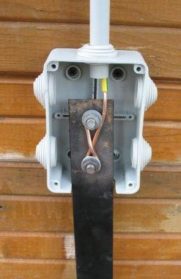
All design elements are securely mated without electric or gas welding. Either one-piece or screw connections are used. A special bolt clamp made of brass or stainless steel is used to join the ground conductor to the mounted electrode.
E1.2. Calculation of the obtained ground resistance
Calculation (detailed description) is nearly the same calculation of a single electrode from p. D2.2. except cross-section dimensions - diameter of modular grounding electrode doesn't exceed 20 mm.
On the example of a thirty-centimetre composite electrode made of copper-bonded pins with the diameter of 14 mm ,mounted in a pit 0.5 meters deep. The soil, in which this electrode will be installed, will be homogeneous loam to simplify the calculation, it is common in Russia, with the resistivity of 100 Ohm * m.
The calculation is carried out in one stage.
Ground resistance of a single vertical ground electrode is calculated as follows

Where:
P – удельное электрическое сопротивление грунта (Ом*м) – soil electric resistivity (Ohm*m)
L – длина электрода (м) – electrode length (m)
d- диаметр электрода (м) –electrode diameter (m)
T-заглубление электрода (м) – Electrode burial (m)
R1 will be 4.7 Ohm (When p = 100 Ohm*m, L = 30 m, d = 0.014 m (14 mm), T = 15.5 m (T - distance from the upper ground level to the middle of the buried electrode)).
This result is worse than that of the electrode having a diameter of 100 mm, but let me note - reduction of the electrode diameter in 7 times (700%) caused an increase in ground resistance on 27% only.
E1.3. Assembling
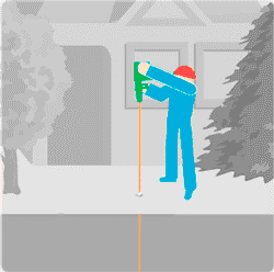
Installation of modular grounding is very easy and can be performed even by a girl.
The pins are hammered into the ground one after another with a jackhammer gradually increasing the depth of the ground electrode. The jackhammer is placed over the pin.
Tasks for the installer: to hold a hammer evenly over the pin (not "suspended", that is the hammer does not press on the hands with its weight, but on the mounted pin) and build up the electrode - to set the next pin over the one already buried.
If the installation is carried out outside the building, then installation of modular grounding / ground electrode is carried out in a pit of a short length and 0.5 meters deep which also fits a ground conductor (copper wire or traditional steel tape), going to the object (switchboard).
If the installation is carried out inside the building (in the basement), the ground electrode installation is carried out at the floor level. Next, the resulting ground electrode is switched to the switchboard by a copper wire.
Both when using a steel tape and using a copper wire for the connection with the pin, a bolt clamp made of brass or stainless steel is mainly used.
Sometimes you can find a way to connect using exothermic welding (a mixture of combustible material with copper dust fills the place of contact of the conductor and the pin, welding them together). But it's exotic.
You can get more information about installing threaded pins see YouTube (link).
UPD: A jackhammer can be rented for a day (from 500 to 700 rubles) or bought at almost any power tools store (from 9 to 10 thousand rubles.).
E1.4. Advantages and disadvantages
Advantages:
- simplicity and ease of installation. All operations are carried out without serious physical labor by one person without special training.
- high efficiency of the ground electrode, providing low ground resistance
- supercompactness, allowing to mount the ground electrode on a very small area or in basements
- long service life of the ground electrode (up to 100 years in clay loam)
- seasonal INdependence of grounding quality. In winter, due to the freezing of the soil, the resistance of such a ground electrode remains almost unchanged due to the fact that only 5-10% of the electrode length is placed in the frozen soil area.
- no welding is required. Design elements are securely connected without it.
Disadvantages:
- impossible assembling in rocky soil. Impossible to batter a nail down into a stone. The rod, due to the high mechanical strength of the structure, can move a small stone, met on the way. It can, having bent away from tangential contact with a big stone, continue the burial not along the vertical axis. But once getting into a sufficiently large stone without the possibility to deviate - it will stand.
- relatively high price of coppper-bonded rods (about 380 rubles per meter) and special equipment for them. The price is much lower than the cost of drilling, but it is clearly higher than the prices for black metal used at the construction of a conventional multi-electrode ground electrode. However, it is more objective to compare not the "naked" cost of materials but the cost of all expenses for the construction of the ground electrode system. It often turns out that the total cost is comparable or even lower than for the modular grounding (for example, due to a banal save on shipment of materials to the site).
E2. Electrolytic grounding (for permafrost or rocky soils)
E2.1. Solution features
E2.1.1. Ease of use in permafrost or rocky soils
E2.1.2. Compactness
E2.1.3. Formation of talik
E2.1.4. No welding
E2.2. Calculation of the obtained ground resistance
E2.3. Assembling
E2.4. Advantages and disadvantages
Let me remind you of the method mentioned in p. D1.5. sometimes used for a substantial reduction of ground resistance.
Salinization of soil in the place of electrode placement by adding of a large amount of cooking salt NaCl. When it is dissolved in the ground (desalination(wiki)) the concentration of ions involved in the charge transfer, dramatically increases, and thus reduces its (ground's) electrical resistance.
With an undeniable positive virtue of this method, as well as its simplicity and cheapness - it has two huge drawbacks:
- at the expense of leaching out salts from the ground (rain, spring melting of snow), ion concentration falls to a natural level in 2-3 years
- salt causes severe corrosion of steel, destroying the electrodes and the grounding conductor in 3-5 years. These disadvantages threaten by the recovery of the ground electrode "from scratch".
We needed countermeasures to these disadvantages and they are:
- constant maintenance of ion concentration in the soil. In other words, their completion with new portions.
- use of materials, minimally exposed to the impact of salt and less aggressive components of these salts, at the construction
As a result, we developed a solution, which was named "electrolytic grounding" (Electrolyte - salt solution).
An electrode of this type presents itself a pipe of short length (usually 2-3 meters) of stainless steel with perforation on almost the entire length. Inside this tube there are pellets (not powder) of a mixture of salts.
In addition to the usual NaCl there are 3 components in the mixture. The composition is a secret of the manufacturers, but we all know how it can be :-)
Two types of pipes are manufactured. In vertical design and horizontal (in the form of a turned letter "Г" - looks like "I___").
Such an electrode is placed in the ground: vertical design - in a pre-made hole of the required depth (2.5 - 3.5 meters); horizontal design - in a pre-dug pit 0.7 meters deep and 2.5 meters long.
.png)
Moisture from the soil is absorbed by the salts in the electrode and comes out as a solution (electrolyte) into the same soil, impregnating it and causing a reduction of its electrical resistivity.
Due to what, the ground resistance of the electrode (pipe) placed in this ground is reduced.
As the salt mixture is in granules and there is a special additive in its composition, it does not dissolve with the entire volume in spring time, when the soil is saturated with water. Thus, we achieve a sustained and uniform electrolyte output from the electrode, gradually increasing (rather than simply preserving) the concentration of ions in the surrounding soil. Usually, the factory "filling" of the electrode lasts for 15 years, after what a repeated "refuelling" is possible.
Using a stainless steel pipe and less aggressive salt mixtures than NaCl, provides durability of such an electrode "shell" for not less than 50 years.
E2.1. Solution features
E2.1.1. Ease of use in permafrost or rocky soils
The design of the electrode of electrolytic grounding can be used in "problem" soils.
Permafrost soils continuously (year-round for hundreds of years) are in a frozen state. Can be met in the North of our country. The depth of soil freezing reaches up to 2 kilometers (in Yakutsk region). Permafrost starts with 1-2 meters from the ground level, ie, from the depth, which cannot be warmed up by the sun in summer.
Permafrost soil is very complex for construction of ground electrodes: it has a very high electrical resistance (100-300 times more than of clay loam), and has the property to "push" metal electrodes out of themselves due to the effect of water expansion when freezing. This happens after summer ground thawing (transition of soil moisture into a liquid state) under these electrodes.
Sandy soil containing a large number of stones of different size - from a fist to meter boulders, is not less complex for the construction of ground electrodes, because stones prevent from plunging electrodes in an ordinary way.
To install this type of electrode in a horizontal design only a small pit of a small depth (0.7 meters) is required, which is relatively easy to dig in both types of soil. Placing of the electrode in the upper soil layer above the permafrost removes the "push" effect.
-2.png)
Small burial of the electrode makes it possible and its limited use in rocky soils- if there is at least a meter layer of loose soil (for "soaking" electrolyte) over the strong monolith.
E2.1.2. Compactness
An electrolytic grounding electrode 12 times more effective than a conventional steel electrode of the same size. This means the number of necessary elements of the ground electrode deceases 12 times and thus, its area, occupied by it, significantly reduces.
At the same time, the dependence of ground resistance weakens because of the season due to a decrease of water freezing point at the increase of soil concentration in it to -5 degrees (the temperature of ordinary soil under a snow cap). This removes the need for the use of additional grounding electrodes to compensate the growth of resistance in winter.
E2.1.3. Formation of talik
There is a negative aspect of the electrode property to reduce the soil freezing point. A talik zone is formed around the electrode (wiki), which might be a danger for the basement of a nearby building or pavement. Talik area on the ground surface presents itself an oval of about 3 x 6 m. Therefore, during the project work it is necessary to take this into account and to distance the electrodes from the objects that could be damaged.
-3.png)
E2.1.4. No welding
A special bolt clamp made of brass or stainless steel is used to join the ground conductor to the mounted electrode.
E2.2. Calculation of the obtained ground resistance
Here is an example of ground resistance calculation of a horizontal electrode, because it is the most common variant in practice, having a length of the horizontal part of 2.4 meters and its diameter of 65 mm. As usual, the soil will be a homogeneous clay loam with the resistivity of 100 Ohm * m.
Ground resistance of a single horizontal ground electrode is calculated as follows:
In case of an electrode of electrolytic grounding a coefficient is added to the formula, describing the electrolyte concentration in the soil around this electrode:
The coefficient ranges from 0.5 to 0.05. It gradually decreases, because electrolyte penetrates into the soil to a greater volume, while increasing its concentration. In normal soil it is 0.125 in 1-2 months of leaching of salts. The process can be accelerated by adding water to the electrode at the final assembly stage.
R1 will be 4.14 Ohm (C = 0.125, p = 100 Ohm * m, L = 2.4 m, d = 0.065 m (65 mm), T = 0.6 m (T - distance from the upper ground level to the middle of the buried electrode)).
An excellent result for a single ground electrode of 2.4 meters only!
But, as always, the price paid for the result is in the price of such an electrode ... We will talk about it below in p. D2.4. (disadvantages).
E2.3. Assembling
Installation of electrolytic grounding electrode of horizontal design is the easiest way I've ever met. In fact, it is a banal electrode burial to a shallow depth.
A pit of 0.7 meters deep and 2.5 meters long is dug. An electrode is put at the bottom. Using a clamp bolt, a grounding conductor is connected. The pit is filled up.
Additionally, you can pour 5 liters of water into the throat of the electrode to speed up the leaching process.
E2.4. Advantages and disadvantages
Advantages:
- simplicity and ease of installation.
- very high efficiency of the ground electrode, providing low ground resistance
- compactness, allowing to mount the ground electrode on a small area. However, in view of a negative feature, described in p. D2.1.3.
- long service life of the ground electrode (at least 50 years) with its "refueling" of salt mixture. The solution was initially created with this property.
- very weak seasonal dependence of grounding quality
- no welding is required. Design elements are securely connected without it.
Disadvantages:
- high price of the electrode (40-60 rubles per electrode), which limits its widespread use. It is recommended to use electrolytic grounding in permafrost or rocky soils, where conventional construction methods do not allow to achieve the needed result or cost even more.
- need for distancing them from building foundations and roads
That's all. Thank you for your attention! Sorry for the large amount of information.
You may ask questions in the comments or directly using my coordinates, specified in the profile. I am always happy to help in the best of my ability and knowledge to everybody who is interested.
Do not hesitate :-) Remember: there are no stupid questions - there are stupid answers.
PS My knowledge in the field of protective devices and power grids are scarce and superficial. Please keep this in mind.
Alexey Rozhankov, technical expert.
The following materials were used to prepare the article:
- Electrical Installation code (EIC), part 1.7 in the seventh edition (link)
- GOST R 50571.21-2000 (IEC 60364-5-548-96)
Grounding devices and systems of equalizing electrical potentials in electrical installations, containing information processing equipment (link)
- Manual for lightning protection of buildings and structures AD 34.21.122-87 (link)
- Technical memo 11/2006 of "Roselectromontazh" Association (link)
- Underground corrosion (United States. National Bureau of Standards. Circular 579) Author: Melvin Romanoff; Publisher: U.S. Govt. Print Off., 1957)
- Publications on the site "Grounding on ZANDZ.com"
- Own experience and knowledge
Related Articles:
 Why Cannot Vertical Earthing Devices Be Installed Close to Each Other?
 Electrolytic Grounding in Permafrost Soils: Should Vertical of Horizontal Electrodes Be Used?
