Command and control center is a structure in an airport or an airfield where centralized management of aircrafts and special vehicle movement across the airfield is performed. There are no special requirements to the lightning protection of the command and control center according to regulatory documents. It is important to ensure the required reliability of lightning protection. The ZANDZ Technical Center has received a request to calculate the lightning protection for a command and control center in Ivanovo Region. Let us continue with more detailed review of our offered solution.
Calculation of a lightning protection system for the command and control center in Ivanovo Region
Facility: A command and control center in Ivanovo Region.
.jpg)
План кровли - Roof plan
Figure 1. Facility plan.
Task: To perform calculations for a lightning protection system for a command and control center in Ivanovo Region.
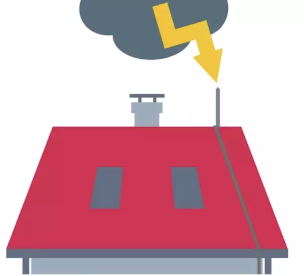
Protection of buildings against lightning strikes is provided by using lightning arresters. Lightning arrester is a device that is elevated over the protected facility, through which the lightning current goes into the ground bypassing the protected facility. It consists of a lightning rod that accepts the lightning discharge, a current collector, and a grounding electrode.
The solutions to ensure the requirements to the lightning protection system for the command and control centre in Ivanovo Region:
the activities were made in accordance with the Electrical Installations Code (EIC), Rev. 7, Chapter 1.7, SO 153-34.21.122-2003 Guidelines for Lightning Protection of Buildings, Structures, and Industrial Utilities (hereinafter referred to as SO), and RD 34.21.122-87 Guidelines for Lightning Protection of Buildings and Structures (hereinafter referred to as RD).
The protected facility is classified as a conventional facility in terms of lightning protection according to SO and to Category 3 according to RD.
A set of arrangements ensuring compliance with the lightning protection requirements is based on the following solutions:
- the facility's lightning protection is made as a lightning grid using a zinc-plated steel wire with a diameter 8 mm laid with a step of not more than 12 x 12 m. The grid is made such that the current would have at least two different paths to the grounding arrangement. Downdrops to the grounding arrangement are made with the step not less than 25 m along the building perimeter, with 4 downdrops in total;
- main conductor cables are mounted (with mounting step 0.6 to 1 m):
- on the slopes of the roof using clamps GL-11747A;
- on a flat roof using clamps GL-11711;
- to the walls using clamps GL-11703A;
- metal fencing is also used as current collectors for the grid;
- connection and branching of current collectors are made using clamps GL-11551A;
- all metal elements located on the roof (pipe hoods, fencing) should be attached to the lightning arrester grid using clamps ZZ-005-064.
- The current collectors are attached to antennas and rods of aircraft warning lights using clamps GL-11514N.
A set of measures to ensure the requirements for the grounding arrangement is based on the following solutions:
- installation of a grounding arrangement consisting of a horizontal electrode (steel zinc-plated strip having cross-section 4 x 30 mm), depth 0.5 m, laid as a circuit around the building, and 4 x 3 m vertical electrodes (rods made of zinc-plated steel having diameter
- 14 mm);
- horizontal electrodes are interconnected using clamp ZZ-005-064;
- current collector is connected with the output of the zinc-plated ground strip using control clamp GL-11562A;
- design of the grounding arrangement corresponds to item 1.7.55 of the EIC. Grounding arrangements for protective grounding and grounding for lightning discharges are common.
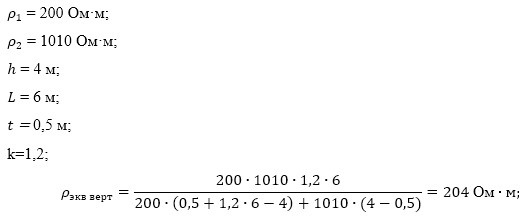
Let's estimate the equivalent soil resistivity according to FFI:
Warning! In case the Customer provided erroneous and limited soil data, the above calculation of a grounding arrangement is considered incorrect. If the soil resistivity differs from the calculated one, it is necessary to perform computations with a real value. If the normalized impedance of the grounding arrangement is exceeded, there must be introduced the design corrections.
Equivalent soil resistivity for vertical electrodes
Ом м - Ohm m
Экв верт - Eq vert
Equivalent soil resistivity for horizontal electrodes
Equivalent value for soil resistivity can be calculated according to Table 7.2 of the reference book "Protective Grounding and Electrical Installation Neutral Grounding" by Mankov and Zagranichny.
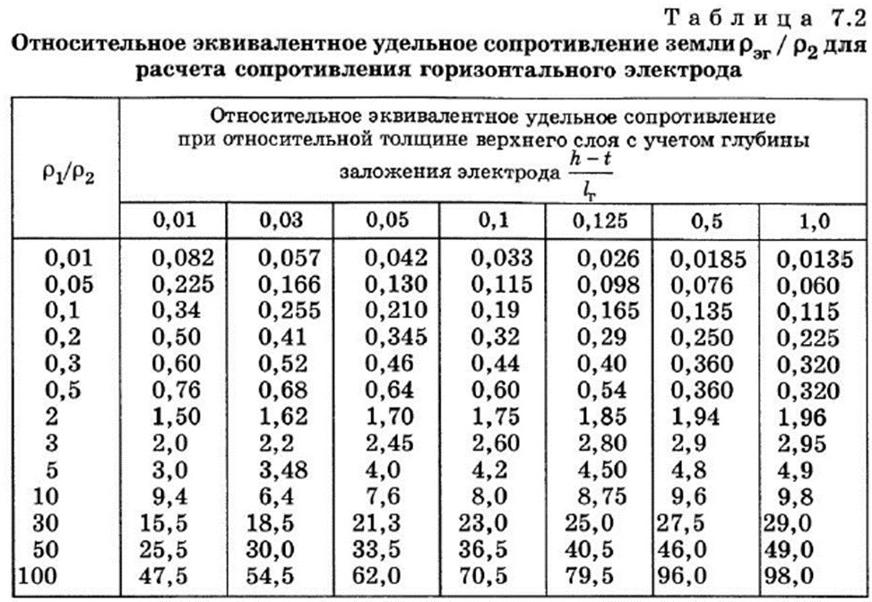
Таблица 7.2 - Table 7.2
Относительное эквивалентное удельное сопротивление при относительной толщине верхнего слоя с учетом глубины заложения электрода - Relative equivalent resistivity at the relative thickness of an upper layer based on the electrode depth
Let's calculate the required values:
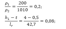
According to tabular data and using linear interpolation, calculate
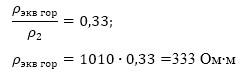
Calculation of a grounding arrangement resistance.
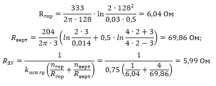
The rated resistance of the grounding arrangement is 5.99 Ohm, which is less than the required value of 30 Ohm.
Figure 2 shows hardware layout.
Table 1 includes the list of required hardware and materials.
.jpg)
Условные обозначения - Legend
Figure 2. Hardware location for the lightning protection system of a command and control center in Ivanovo Region.
Table 1. List of material requirements.
Do you have any questions about lightning protection for the command and control station or other facilities? Please, contact the ZANDZ Technical Center!
Related Articles: