16.08.16
At the installation of a grounding device, you may encounter a situation where installation space is limited. It is impossible to establish a deep-laid ground electrode due to strong soil, for example, in conditions of permafrost, rocky and sandy soil, or there is only a small area to place the grounding contour. For such cases, electrolytic grounding system has been developed. It allows providing the necessary resistance in extreme conditions. In this article we describe installation of such a system in detail on the example of our partner.
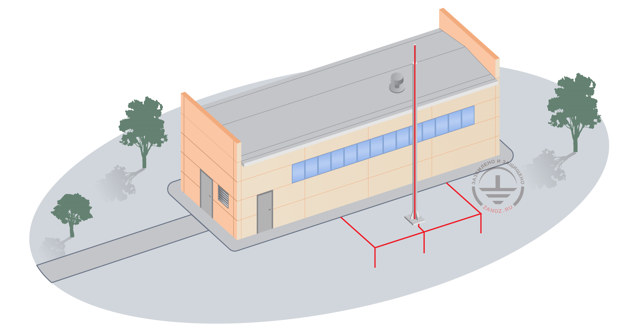
In the end of June 2016, our Expert of the ZANDZ.com Club, The company "N G N Group" Ltd gave us a chance to visit the customer facility in order to make pictures and video of installation of electrolytic grounding system. In the article you will see how do the components of electrolytic grounding look in real life, what are they responsible for and what is the difference of electrolytic grounding from modular grounding? There was a depth limitaton due to underground utilities.
Electrical equipment is in the priventative clinit at the refinery was an installation object. The soil at the site is clay loam. There is a limit on the depth of putting ground electrodes due to underground utilities, so to ensure the rated resistance it was decided to install electrolytic grounding system ZANDZ ZZ-100-102. The installation was carried out by the customer in accordance with the EIC 7 th ed. Chapter 1.7
A list of materials used in the installation:
|
№ |
Fig. |
Product item |
Product |
Quantity |
|
|
1. |
|
ZZ-100-102 |
1 |
||
|
2 |
|
ZZ-005-064 |
1 |
||
|
3. |
|
ZZ-007-030 |
1 |


During the installation it was necessary to perform the following works:
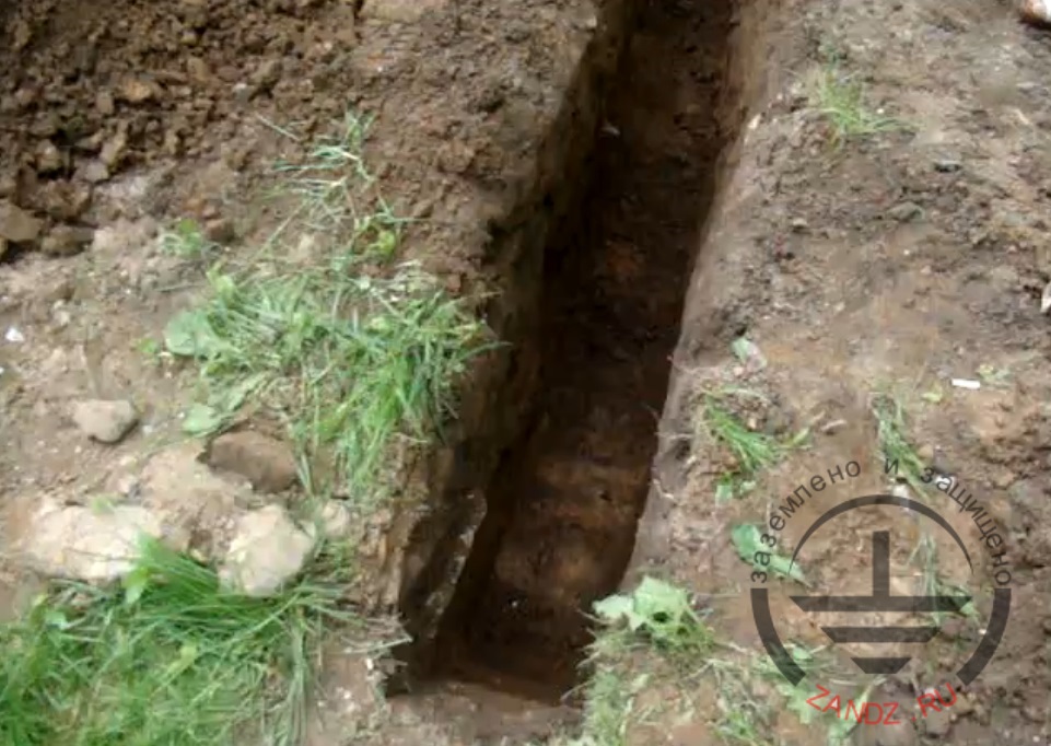
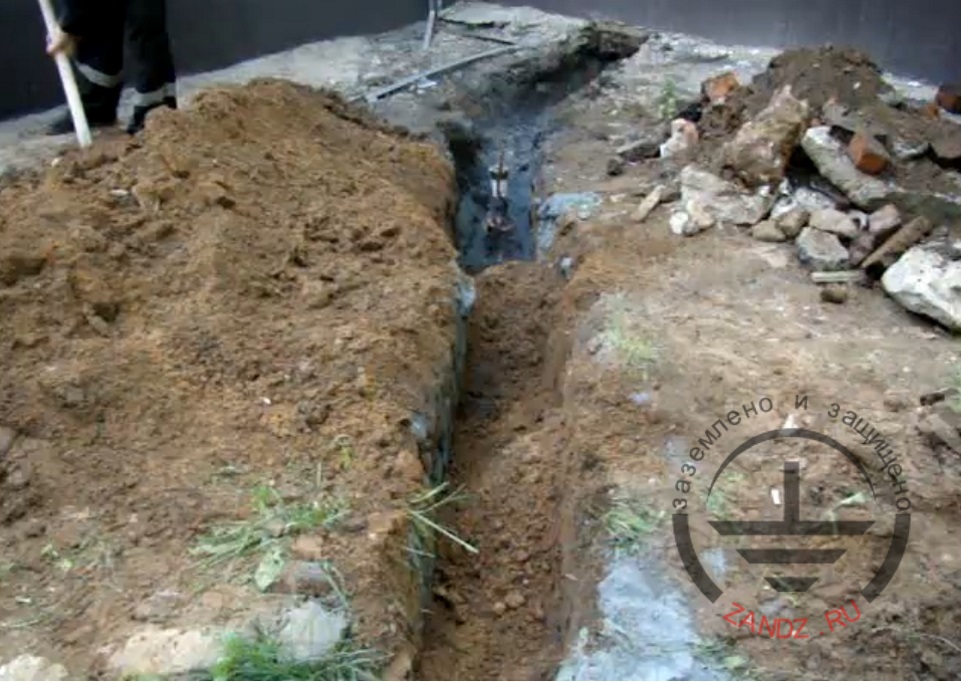
1. Prepare two trenches: 0.7 meters deep and 2.5 meter long for laying the L-shaped electrode and a trench for laying wire from the ground electrode to the building.
2. Put half of the bag of near-electrode filler to the first trench, distributing it evenly across the depth of burial. This mixture of graphite chips with a special kind of clay mineral is a replacement of the soil and increases the contact area of the electrode with soil due to the leaching process.
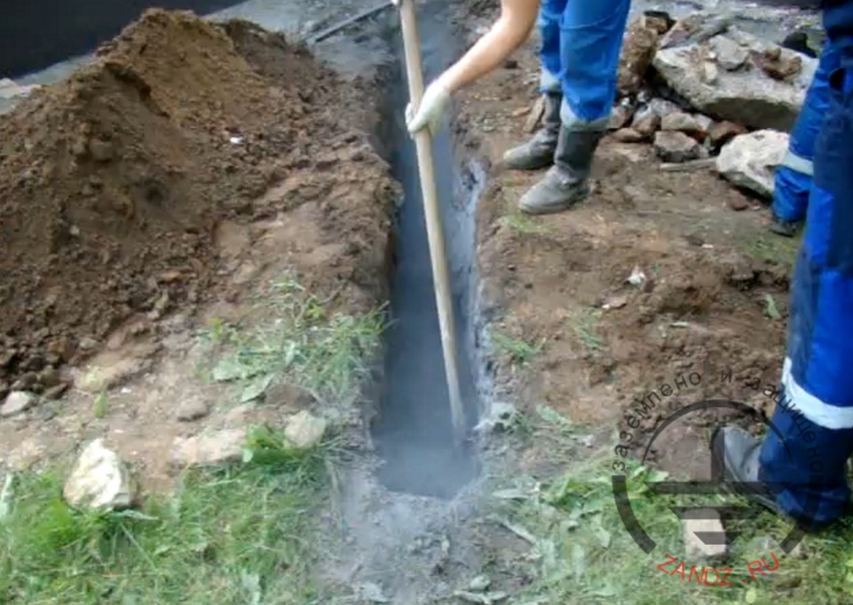
3. Place the electrode into the channel and cover it with the remaining two sacks of near-electrode filler. The electrode is in the form of a hollow tube "L" with a mixture of mineral salts inside. Therefore it provides ground resistance 12 times less than the conventional ground electrode of the same size.
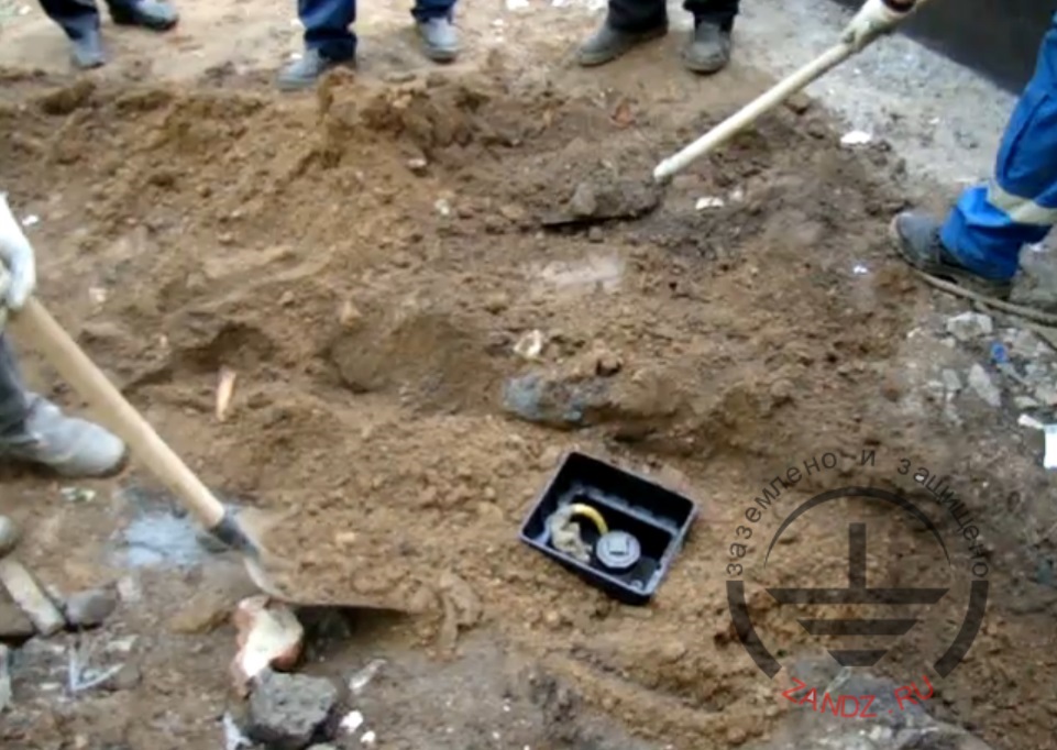
4. Cover the trench with the ground, leaving 0.5 meters of the top of the electrode.
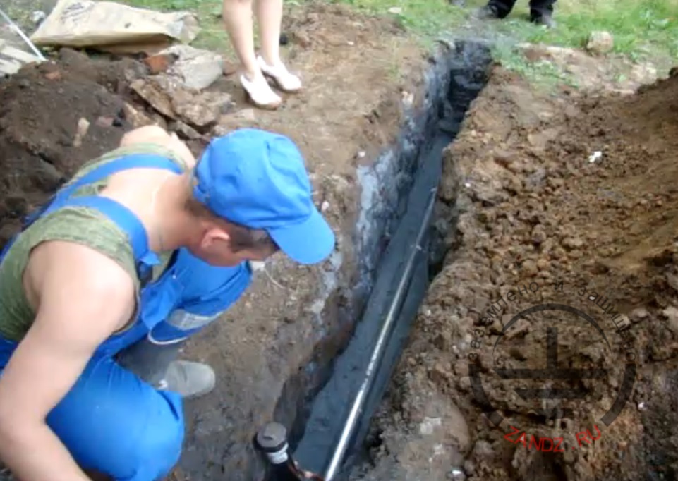
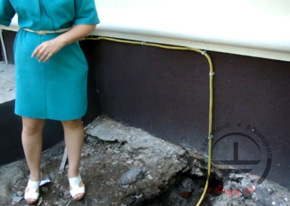
5. Route the ground wire in the second tranche from the building to the electrode. The cross -section of the wire should be not less than 25 mm2.
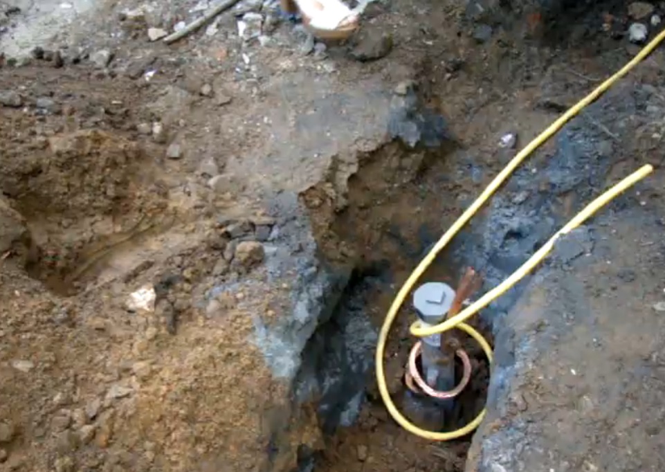
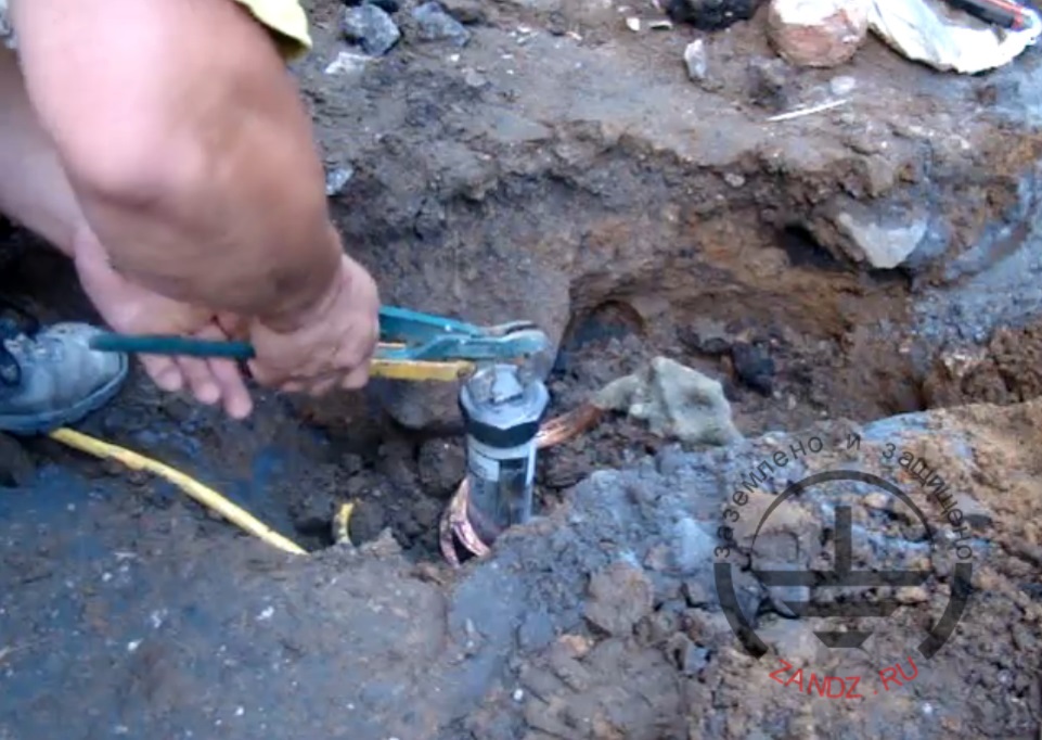
6. Connect the grounding conductor to the withdrawal of the electrolytic electrode, using a cross-shaped stainless steel clamp.
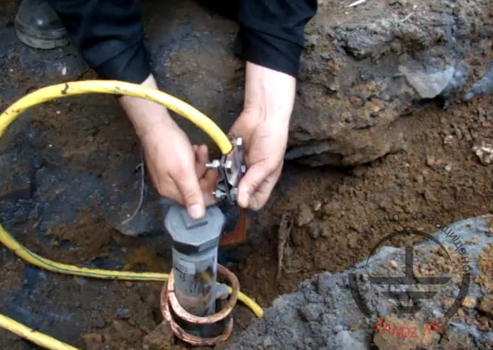
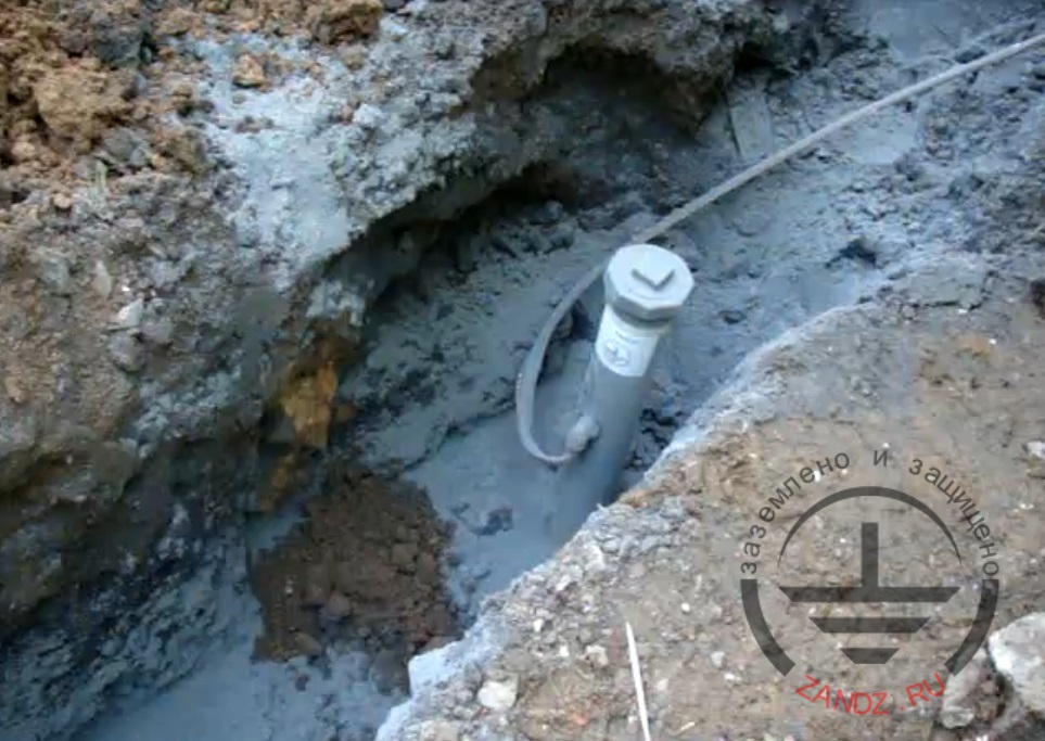
7. Insulate the clamp using waterproof tape, the use of which will protect the connection from soil and galvanic corrosion by displacing moisture and air from the connection point.

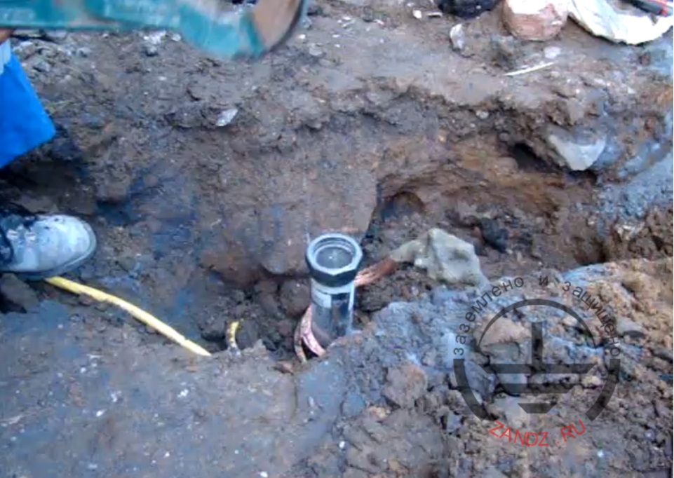
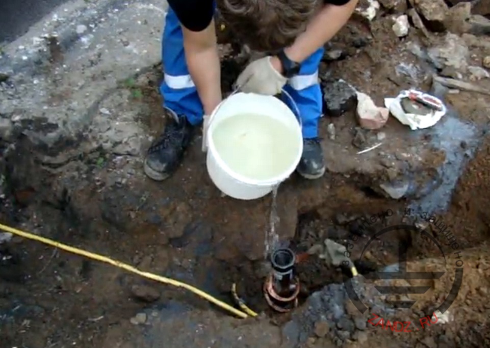
8. Release the hole of the electrode from the plug and fill the electrode with 5-7 liters of water. This measure is necessary to accelerate the leaching of salts from the electrode.
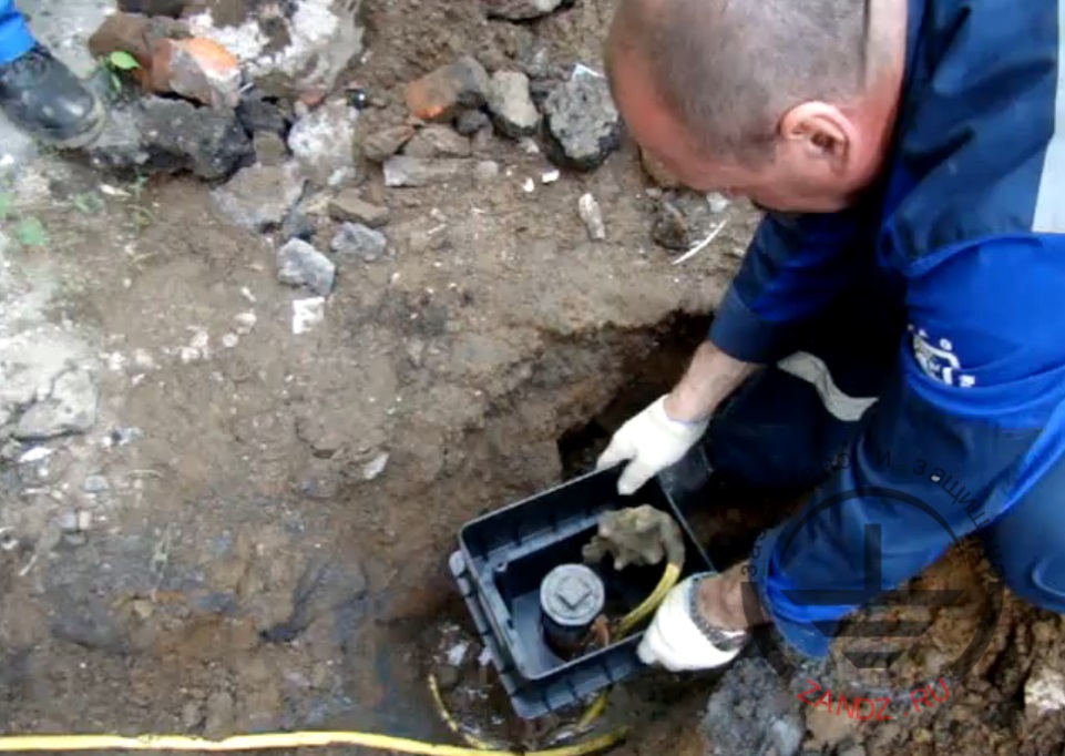
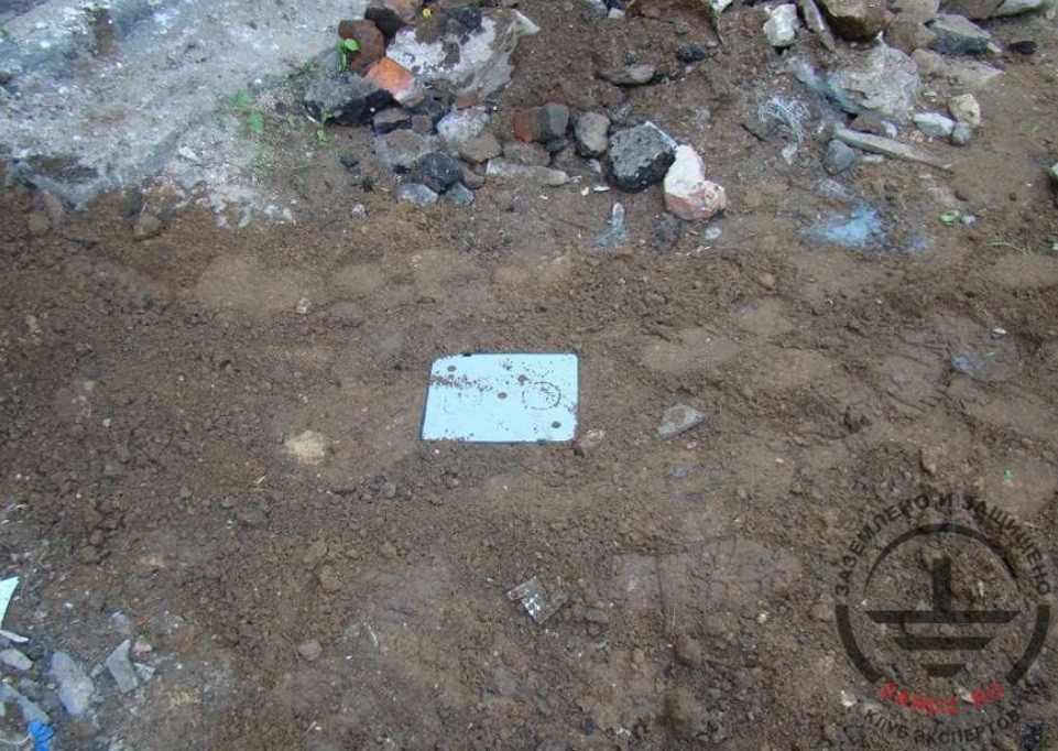
9. Put a special pit, allowing to maintain grounding on the vertical part. The hatch of the pit must be located at the ground level. Fill the channel with ground.
Full video of the installation:
ZANDZ ZZ-100-102 electrolytic grounding system
After the installation - electrolytic grounding electrode requires refueling by the filler only in 10-12 years, providing the required ground resistance during the entire service life of 50 years. This work is an effective example that electrolytic grounding system can be used not only in the conditions of permafrost, rocky and sandy soil, but also in any other ground, where there is a restriction on the installation place of the ground electrode system.
Do you also have photos of grounding or lightning protection installation? Participate in the contest for the best photo-report of the installation! Post them in your Personal Account in section "Works" and get money certificates for the purchase of copper-bonded steel grounding. In more detail.
Related Articles:


.jpg)