Last week, we told about the fountain grounding in permafrost in Yakutia. Our today's facility is also located in permafrost, but in another region. The customer requested to develop both grounding and lightning protection systems for a concrete plant. While lightning protection system was rather conventional, grounding is worth close attention.

To provide grounding for a concrete plant, like in the previous exemplary calculation, ZANDZ technical specialists used a horizontal electrolytic grounding. This time, estimated resistivity was even more, 1,898 Ohm*m, because the main soil component was represented by landwaste. This sedimentation rock soil has a high resistivity on its own, but its location in permafrost soils increases the level of complexity of the task even more.
Read our article to see the exemplary calculation and know what solution was proposed to provide lightning protection and grounding for a concrete plant in these challenging conditions.
Task
To calculate the lightning protection and grounding systems for the concrete plant.
Solution
Calculations of the lightning protection are made in conformity with the following documents:
- "Electrical Installations Code" (hereinafter, EIC), EIC 7th edition.
- "Instructions for the installation of lightning protection of buildings, structures, and industrial communications" SO 153-34.21.122-2003 (hereinafter, SO).
- "Instructions for mounting the lightning protection of buildings and structures" RD 34.21.122-87 (hereinafter, RD).
The protected plant is classified as a conventional facility in terms of lightning protection according to SO and to Category 3 according to RD.
Description of the plant's lightning protection system
A set of arrangements ensuring compliance with the lightning protection requirements is based on the following solutions:
- 2 x 10 m lightning rods are installed by their attachment to the wall. It is taken into account that 1.8 m of the height of interception rods are necessary for mounting.
- Lightning arresters are interconnected to arrange two current collectors using galvanized steel wire D = 8 mm from each lightning arrester. The main conductor cables are mounted (with mounting step 0.6-1 m):
- on the slopes of the roof it is carried out using terminals GL-11747A;
- to the walls with connection terminals GL-11703A.
- Connection and branching of main conductors are usually made using terminals GL-11551A.
A set of measures to ensure the requirements for the grounding arrangement is based on the following solutions:
- Installation of a grounding arrangement consisting of a horizontal electrode (steel zinc-plated bar with cross-section 4 x 30 mm), depth 0.5 meter.
- The connection of the main conductor cable with the output of the galvanized ground strip is performed with the control terminal GL-11562A.
- To provide the rated resistance of the grounding device, electrolytic grounding ZANDZ ZZ-100-102 is proposed.
- There was made an installation of 8 sets of electrolytic grounding ZANDZ ZZ-100-102.
- All sets were placed at a distance of 6 meters with a parallel arrangement to achieve the acceptable utilization rate and an optimal volume of electrolyte distribution in the soil.
- Because of the formation of a talik zone in the oval form 3x6 meters in size, the electrodes must be placed at an appropriate distance off the foundations of buildings and other engineering structures.
- The grounding devices are connected using clamps ZZ-005-064.
- The design of the grounding arrangement corresponds to clause 1.7.55 of EIC Grounding arrangements for protective grounding and grounding for lightning discharges are common.
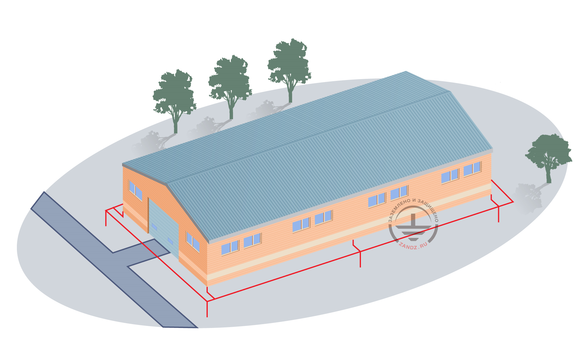
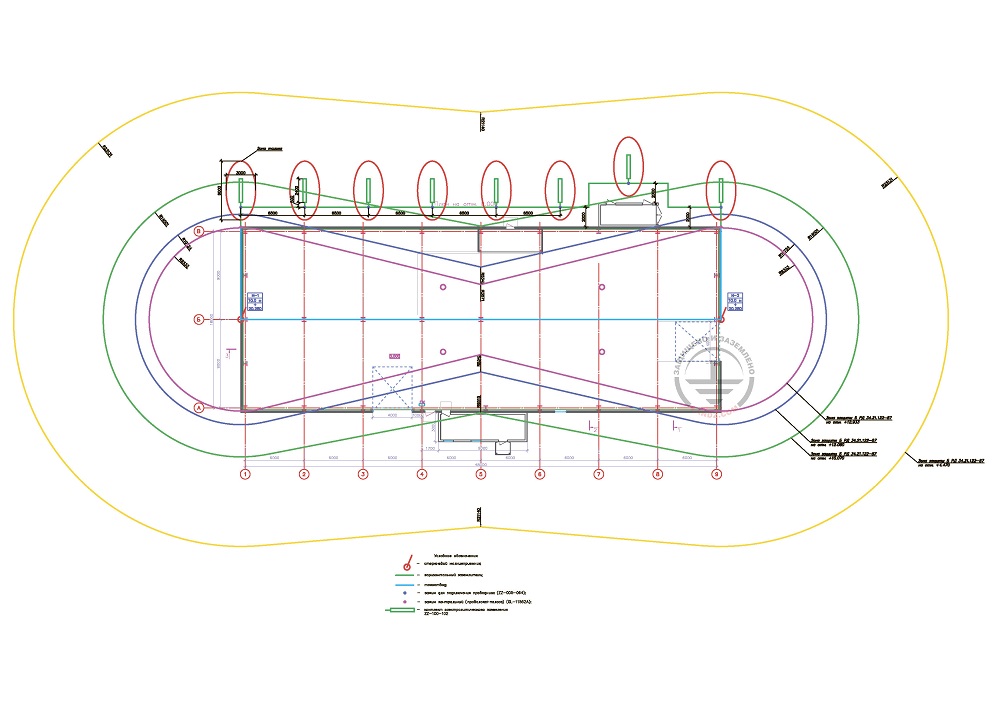
The location of the elements of the lightning protection system and the grounding arrangement is shown in Figure 1. The protection zone corresponds to zone B, constructed as per Appendix 3 to RD.
Figure 1. Layout of elements of the lightning protection and grounding arrangement for the concrete plant.
Grounding arrangement resistance calculation:
According to the customer's data, the soil is frozen: clay loam, sandy cobble, and landwaste.
Estimated soil resistivity is taken as a frozen landwaste resistivity that is equal to 1,898 Ohm∙m.
Warning! In case the Customer provided erroneous and limited soil data, the above calculation of a grounding arrangement is considered incorrect. If the soil resistivity differs from the calculated one, it is necessary to perform computations with a real value. If the normalized impedance of the grounding arrangement is exceeded, there must be introduced the design corrections.
The calculation is made using formulas provided in the Grounding Calculation page.
The calculation formulas with the completed data are shown below.

Ом - Ohm
Гор - Hor
Исп - Util
The estimated resistance of the grounding device is 9.38 Ohm, which is less than the required resistance 10 Ohm according to the EIC 1.7.103.
Components of the lightning protection and grounding system for the concrete plant
Do you have any questions regarding lightning protection and grounding for a concrete plant in permafrost? Please contact the ZANDZ Technical Center!
Related Articles:
.jpg)


.png)


