The main purpose of the transformer substation is acceptance, voltage transformation and distribution of electricity in the consumer power systems. Considering all this, grounding is the overarching measure for the protection of electrical equipment and electrical installations at hazardous voltages and currents that may arise in cases of failure and misuse. Designers often wonder how to perform grounding of a transformer substation, especially if the object is located in rocky ground. Let's consider the actual calculation of substation grounding, carried out by our technical center!

Object: The object of the protective grounding installation is transformer substation 35/10 kV. The soil at the location of TS 35/10 kV is rocky ground with loamy solid filler. Specific soil resistance is taken equal to 1000 Ohm ∙ m.
Solution: In accordance with the EIC p.1.7.96, 1.7.97 and 1.7.104 for electric installation with the voltage above 1 kV in networks with the isolated neutral (35-10 kV), the grounding device resistance should not exceed 4 Ohms.
The set of measures to ensure the necessary requirements to the grounding device is presented in two versions:
Option 1. Electrolytic grounding.
To ensure the rated resistance of the grounding device, it is offered to use ZANDZ electrolytic grounding, specifically designed for use in permafrost and stony soils.
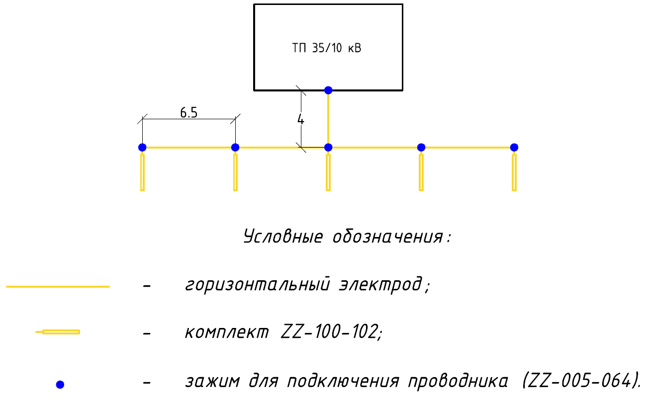
- Installation of five kits of electrolytic grounding ZANDZ ZZ-100-102 is carried out. The kits are installed at the distance of 6.5 meters at the parallel installation for an acceptable use ratio and optimal volume of electrolyte distribution in the soil.
- The electrolytic kits are united by a horizontal electrode made of stainless steel copper-bonded tape with the cross-section 4x30 mm, depth 0.5 m.
- A horizontal electrode 4 m long is laid to the wall of the building.

Figure 1. The circuit arrangement of the grounding device elements
Условные обозначения- notions
Горизонтальный электрод – horizontal electrode
Комплект - ZZ-100-102 kit
Зажим для подключения проводника – Clamp for conductor connection
Calculation of resistance of a grounding device:
1). Resistance of ZZ-100-102 kit:

where C - a non-dimensional factor describing the electrolyte content of the surrounding soil;
ρ – specific soil resistance Ohm*m
L - ground electrode lengh, m;
d - ground electrode diameter, m;
T– deepening – distance from the ground surface to the ground electrode system
2). Horizontal electrode resistance:

ρ – specific soil resistance Ohm*m
b - width of the horizontal electrode tape, m;
h - laying depth of the horizontal mesh, m;
Lгор - horizontal electrode length, m;
3). Impedance of the grounding device:

Where n – number of kits
kисп- Utilization ratio;


The design resistance of the grounding device is 7.48 ohms, which is less than the required impedance 8 ohms, obtained by increasing the rate of 4 ohms to 2 times.
The list of the required materials:
| No. | Fig. | Product item | Product | Q-ty. |
| 1. |  |
ZZ-100-102 | ZANDZ electrolytic grounding kit (horizontal; 3 m) | 5 |
| 2. |  |
GL-11075-20 | GALMAR Copper-bonded tape (30 * 4 mm / S 120 mm²; coil 20 meters) | 1 |
| 3. |  |
GL-11075-10 | GALMAR Copper-bonded tape (30 * 4 mm / S 120 mm²; coil 10 meters) | 1 |
| 4. |  |
ZZ-005-064 | ZANDZ Clamp for connecting conductor (up to 40 mm) |
6 |
| 5. |  |
ZZ-007-030 | ZANDZ Water-proof tape | 2 |
Option 2. Modular grounding
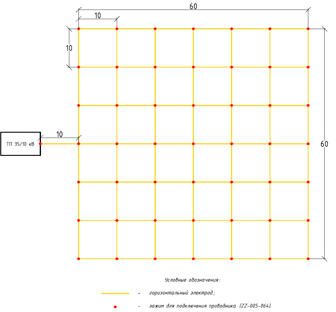
- A horizontal mesh with the dimensions 60x60 m, 10 m of the cell pitch is made. The mesh is made of copper-bonded stainless steel tape with the cross -section 4x30 mm, laying depth- 0.5 m.
- A horizontal electrode 10 m long is laid to the wall of the building.
- Installation of vertical electrodes is not made, because it is complicated without the drilling of wells, the there is no necessary equipment for drilling.

Figure 2. The circuit arrangement of the grounding device elements
Calculation of resistance of a grounding device:
1). Horizontal electrode resistance:

ρ – specific soil resistance Ohm*m
b - width of the horizontal electrode tape, m;
h - laying depth of the horizontal mesh, m;
Lгор - horizontal electrode length, m;
2). Impedance of the grounding device:

Where n – number of kits
kисп- Utilization ratio;


The design resistance of the grounding device is 7.91 ohms, which is less than the required impedance 8 ohms, obtained by increasing the rate of 4 ohms to 2 times.
The list of the required materials:
| No. | Fig. | Product item | Product | Q-ty. |
| 1. |  |
GL-11075-50 | GALMAR Copper-bonded tape (30 * 4 mm / S 120 mm²; coil 50 meters) | 17 |
| 2. |  |
ZZ-005-064 | ZANDZ Clamp for connecting conductor (up to 40 mm) | 50 |
| 3. |  |
ZZ-007-030 | ZANDZ Water-proof tape | 17 |
Based on the results of calculations and economic feasibility, the best choice is grounding formed on the basis of electrolytic grounding kits. The cost of materials of this variant is 1.5 times lower than the cost of the components of a modular grounding. Drawing up the estimates for the grounding organization, it is necessary to consider the cost of works on the installation.
Looking for qualified installers and designers? You will find them here! Experts of our club are always happy to help in solving even the most complex problems.
If you have any further questions on the selection and calculation of grounding, contact us and we will help!
See also:
Related Articles:
.jpg)
.jpg)


