The ZANDZ Technical Centre has received a request to calculate the lightning protection and grounding system for a natural gas fuelling complex located in the territory of the administration for underground gas storage (AUGS). Let's consider the solution proposed by our engineers.
Calculation data:
-
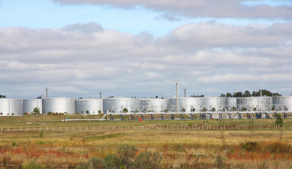
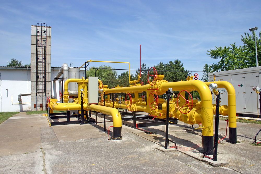
Facility: a natural gas fuelling complex.
-
Facility layout.
-
Heights of the protected zone: 7.5 m and 10 m.
-
Soil resistivity: 100 Ohm*m.
Task:
-
Calculate the external lightning protection system.
-
Calculate the grounding device.
Solution:
The activities have been performed according to:
-
EIC Rev. 7, Electrical Installations Code (hereinafter referred to as the EIC);
-
RD 34.21.122-87 Instructions for Mounting Lightning Protection for Buildings and Structures (hereinafter referred to as RD);
-
SO 153-34.21.122-2003 Instructions for Mounting Lightning Protection for Buildings, Structures, and Industrial Utilities (hereinafter referred to as SO);
A set of arrangements to ensure compliance with the requirements of the lightning protection system for the natural gas fuelling complex is based on the following solutions:
-
The facilities are classified as Category II of the lightning protection. The system reliability shall be at least 0.95
-
The facility lightning protection is made using 25 m lightning arresters (ZZ-201-025).
-
3 m steel copper-plated rods are used as a vertical grounding arrangement.
-
The copper-plated steel strip with a cross-section of 30 x 4 mm, combining all vertical electrodes, is used as a horizontal ground electrode. Strip deepening is 0.5 to 0.7 m.
-
All reservoirs are connected to the grounding arrangement in 2 points.
-
Connection to the grounding device is carried out using ZZ-005-064 clamps.
-
The design resistance of the grounding arrangement is 3.31 Ohm.
-
According to EIC-7 issue, par.1.7.55, Grounding devices for protective grounding of electrical installations for buildings and structures and the 2nd and 3rd categories lightning protection of these buildings and structures, as a rule, shall be common.
Ground terminal resistance calculation:
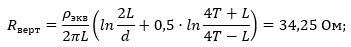
Vertical electrode resistance:
Верт - Vert
Экв - Eq
Ом - Ohm
where ρ ρeq – is equivalent soil resistivity, 100 Ohm·m;
L – is vertical electrode length, 3 m;
d – is vertical electrode diameter, 0.014 m;
T – is depth, i.e. the distance from the ground surface to the ground electrode, 2 m;
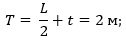
where t – is electrode top depth, 0.5 m.
Horizontal electrode resistance:
Гор - Hor
Ом - Ohm
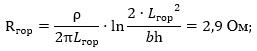
where ρ – is soil resistivity, 100 Ohm·m;
b - is horizontal electrode width, 0.03 m;
h - is horizontal electrode depth, 0.5 m;
Lhor – is horizontal electrode length, 74 m.
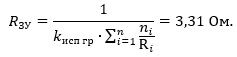
Electrical impedance of the grounding arrangement:
ЗУ - GA
Ом - Ohm
where n is a number of sets, vertical grounding arrangements - 7 pcs, horizontal grounding arrangement - 1 pc;
Kutil – is utilization rate, 0.55.
The calculated resistance of the grounding arrangement is 2,29 Ohm.
Calculation of the protection zone:
Lightning arrester No. 1 - 2 (ZZ-201-025):
h = 25 m;
Cone height according to SO, Table 3.4:
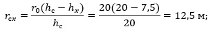
h0 = 0,8h = 20 m;
Cone radius according to SO, Table 3.4:
r0 = 0,8h = 20 m;
Distance between the lightning arresters (maximum):
L = 59 m;
Limit distance between lightning arresters according to SO, Table 3.6:
Lmax = 4,75h = 118,75 m;
L0 = 2,25h = 56,25 m;
Sagging height:
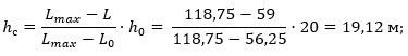
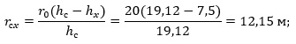
To provide protection with the required reliability, radius rcx at the height h0 = 7.5 m is determined as follows:
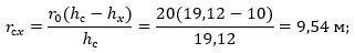
To provide protection with the required reliability, radius rcx at the height h0 =10 m is determined as follows:
Для зоны защиты требуемой надежности радиус r0 на высоте h0 = 7.5 m is determined as follows:
To provide protection with the required reliability, radius rcx at the height h0 =10 m is determined as follows:
The layout of the equipment is shown in Figure 1.
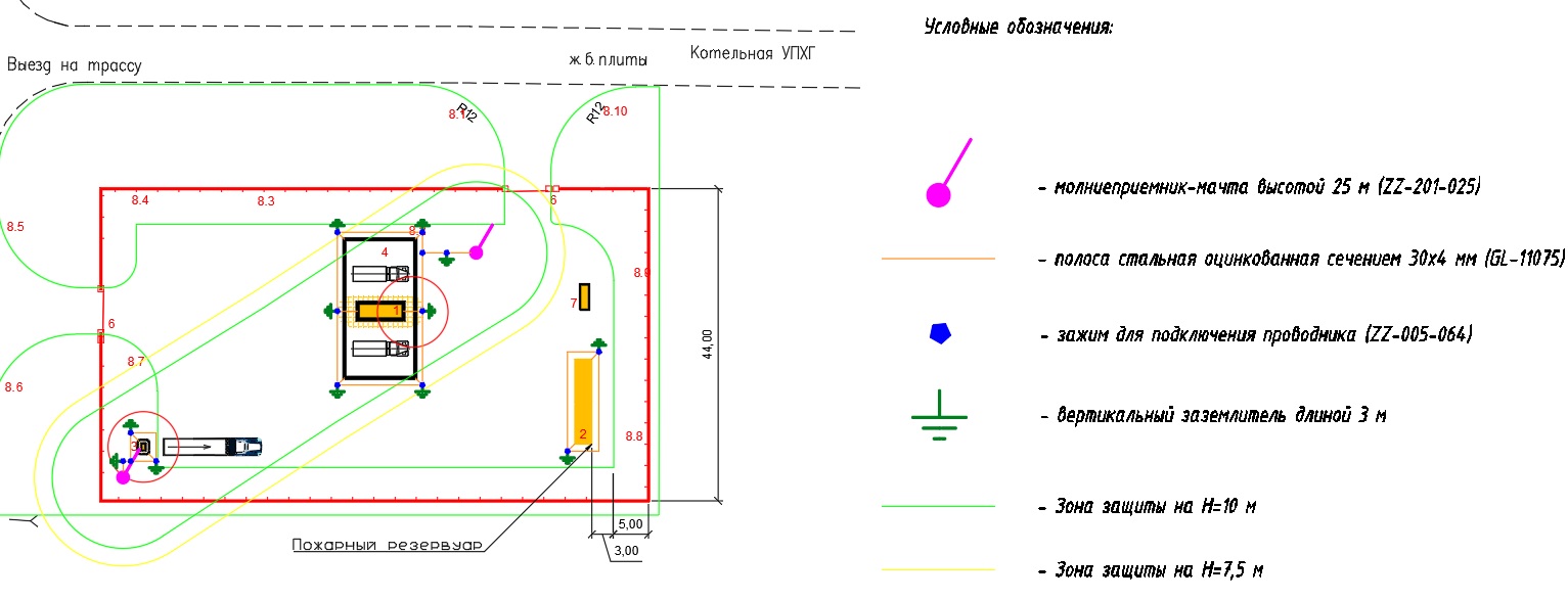
>Выезд на трассу - Road to motorway
Ж.б. плиты - Reinforced concrete slabs
Котельная УПХГ - AUGS boiler
Пожарный резервуар - Fire tank
Условные обозначения: - Legend:
- молниеприемник-мачта высотой 25 м - 25 m lightning rod
- полоса стальная оцинкованная сечением 30х4 мм - Steel zinc-plated bar 30 x 4 mm
- зажим для подключения проводника - Clamp for connecting conductors
- вертикальный заземлитель длиной 3 м - 3 m vertical grounding arrangement
- зона защиты на H=10 м - Protection zone at H = 10 m
- зона защиты на H = 7,5 м - Protection zone at H = 7.5 m
Figure 1. Equipment layout.
The list of necessary materials is provided in Table 1.
Table 1. List of needed materials.
| № | Part number | Name | Quantity, pcs. | Unit weight, kg | Note |
| 1. | ZZ-201-025 | ZANDZ 25 m vertical lightning arrester (zinc-plated steel; with parts embedded under the foundation) | 2 | ||
| 2. | GL-11075-50 | GALMAR Copper-plated strip (30 x 4 mm / S 120 mm²; 50-meter strip bundle) | 3 | 0,98 | В метрах |
| 3. | ZZ-001-065 | ZANDZ Copper-plated threaded grounding rod (D14; 1.5 m) | 24 | 2,00 | |
| 4. | ZZ-002-061 | ZANDZ Threaded coupling | 13 | 0,08 | |
| 5. | ZZ-003-061 | ZANDZ Termination | 12 | 0,07 | |
| 6. | ZZ-004-060 | ZANDZ Guide head for jackhammer attachment | 5 | 0,09 | |
| 7. | ZZ-005-064 | ZANDZ Conductor connection terminal (up to 40 mm) | 20 | 0,16 | |
| 8. | ZZ-006-000 | ZANDZ Conductive grease | 2 | 0,10 | |
| 9. | ZZ-007-030 | ZANDZ Waterproofing tape | 7 | 0,40 | |
| 10. | ZZ-008-000 | ZANDZ Attachment to the hammer (SDS max) | 1 | 0,50 |
Do you have any questions regarding lightning protection for the natural gas fuelling complex? Please contact the ZANDZ Technical Center!
Related Articles: