Today, mobile medical centers intended for computer diagnostics can be assumed as a common fact. The ZANDZ Technical Center has received a request to calculate the lightning protection system for a building made of sandwich panels, wherein a tomographic scanner and a mobile medical site will be located. Let's further consider the proposed solution.

Initial data:
1. facility: a modular building for a computer tomographic scanner;
2. dimensions of the protected facility: 8 m x 8 m x 3.15 m;
3. ridge height: 4.5 m;
4. soil resistivity accepted for the calculations is 100 Ohm * m.
Task:
Calculate the external lightning protection system.
Solution:
The activities have been performed according to:
- EIC, Rev. 7. Electrical Installations Code (hereinafter referred to as the EIC);
- SO 153-34.21.122-2003 Instructions for Mounting Lightning Protection for Buildings, Structures, and Industrial Utilities (hereinafter referred to as SO);
- RD 34.21.122-87 Instructions for Mounting Lightning Protection for Buildings and Structures (hereinafter referred to as RD).
The facility is classified as «conventional» according to SO and as Category 3 according to RD. The required system reliability is at least 0.9.
A set of measures to provide the necessary requirements to the lightning protection system for the building made of sandwich panels for the tomographic scanner is provided by the following solutions:
-
Lightning protection of the facility is made using 2 m ridge lightning rods (GL-11521SS), which are secured with the GL-11525 holders.
-
A copper-plated steel wire (copper coating thickness of at least 70 μm), d8 mm (GL 11149), is used as a current collector.
-
Installation of current collectors is performed using clamps GL-11747A on the roof and GL-11703A on ramparts and vertical surfaces. The clamp installation interval is 0.8 to 1.0 m.
-
The universal GL 11551A clamp is used to connect the rolled products over the length and in assemblies.
-
3 m steel copper-plated electrodes in the locations of the current collector downdrops are used as vertical grounding electrodes.
-
30 x 4 mm steel copper-plated bar combining all vertical electrodes is used as a horizontal grounding device. The distance to the facility foundation is at least 1 m. Strip deepening is 0.5 to 0.7 m.
-
According to the EIC, Rev. 7, item 1.7.55, grounding devices for protective grounding of electrical installations for buildings and structures and Categories 2 and 3 of the lightning protection for these buildings and structures usually should be common.
-
If there are reinforced concrete structures, they should be connected to current collectors/to the grounding device.
-
Connection to the grounding device (external and internal) is made by clamps ZZ-005-064.
-
To provide protection against secondary lightning effects, we should use SDP Class 1+2+3 (CI-821730244).
Results of the calculation performed using the software developed by Krzhizhanovsky Energy Institute (OAO ENIN):
Intensity of lightning discharge into the ground is 4 strikes/square km/year;
The total number of strikes into the system is 0.0065 (once every 154 years).
The total number of breakouts into the system is 0.0004 (once every 2500 years).
The system reliability is 0.939;
The probability of breakout into all facilities of the system is 0.061.
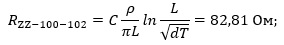
Ground terminal resistance calculation:
Vertical electrode resistance:
Верт - Vert
Экв - Eq
Ом - Ohm
where ρρeq – is equivalent soil resistivity, 100 Ohm·m;
L is vertical electrode length, 3 m;
d is vertical electrode diameter, 0.014 m;
T is depth, i.e. the distance from the ground surface to the ground electrode, 2 m;
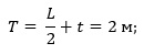
where t is electrode top depth, 0.5 m
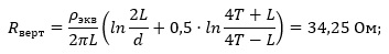
Horizontal electrode resistance:
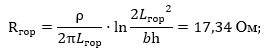
Гор - Hor
Ом - Ohm
where ρ is soil resistivity, 100 Ohm·m;
b is horizontal electrode width, 0.03 m;
h is horizontal electrode depth, 0.7 m;
Lhor is horizontal electrode length, 8 m.
Electrical impedance of the grounding arrangement:
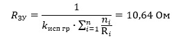
ЗУ - GA
Ом - Ohm
where n is a number of sets, vertical grounding arrangements - 2 pcs, horizontal grounding arrangement - 1 pc;
Kutil is utilization rate, 0.81.
The calculated resistance of the grounding arrangement is 10,64 Ohm.

- Молниеприемник коньковый высотой 2 м - Ridge lightning arrester, 2 m
- Проволока омедненная стальная диаметром 8 мм - 8 mm steel copper-plated wire
- Полоса омедненная стальная сечением 30 х 4 мм - Steel copper-plated bar 30 x 4 mm
- Электрод D = 14 мм, L = 3 м - Electrode D = 14 mm, L = 3 m
Figure 1. Equipment layout.
The list of necessary materials is given in Table 1.
Table 1. List of needed materials.
Do you have any questions regarding grounding and lightning protection of a building made of sandwich panels and intended for the tomographic scanner? Please contact the ZANDZ Technical Center!
Related Articles: