We have received a request to calculate the lightning protection and grounding systems for the instrument building for an earthquake station that is a part of the international system for earthquake monitoring. Thus, the lightning protection system for the instrument building should comply with the international standards, namely lightning protection Level II according to IEC 62305-1, which corresponds to reliability 0.95.

To provide normal operation of sensitive instruments, we needed the resistance for the instrument building being not more than 4 Ohm. A sandy soil was a challenge as it has a high resistivity, but due to the existing casing tube having the grounding resistance of 7.2 Ohm and the installation of electrolytic grounding sets, we could achieve the required standard value.
We suggest considering a solution for lightning protection and grounding for the instrument building in more details.
Task
To calculate the lightning protection and grounding for the instrument building.
Solution
Calculations of the hospital lightning protection are made in conformity with the following documents:
- "Electrical Installations Code" (hereinafter referred to as the EIC), 7th edition.
- "Instructions for the installation of lightning protection of buildings, structures, and industrial communications" SO 153-34.21.122-2003 (hereinafter referred to as SO).
- "Instructions for mounting the lightning protection of buildings and structures" Working Documentation 34.21.122-87 (hereinafter referred to as the RD).
Upon the customer's request, IEC 62305-1 Level II lightning protection system should be designed and installed, which corresponds to Level II according to the SO, and thus the facility should be protected against direct lightning strike with the protection reliability 0.95 according to Table 2.2 of the SO.
Description of the lightning protection system for the instrument building
A set of arrangements ensuring compliance with the lightning protection requirements is based on the following solutions:
- Installation of 4 lightning rods 4 m high is carried out by attachment to the wall. It is taken into account that 0.7 m of the height of lightning arrester are necessary for mounting.
- Lightning arresters are interconnected to arrange two current collectors using zinc-plated steel wire D = 8 mm from each lightning arrester. Downdrops are attached to an artificial grounding arrangement (average distance not more than 15 m).
- The main conductor cables are mounted (with mounting step 0.6-1 m):
- to the walls using clamps GL-11703A.
- Connection and branching of current collectors are made using clamps GL-11551А.
A set of measures to ensure the requirements for the grounding arrangement is based on the following solutions:
- nstallation of two grounding arrangements consisting of a horizontal electrode (zinc-plated steel strip having cross-section 4 x 30 mm), depth 0.5 m, distance to the foundation 1 m.
- To provide the rated resistance of the grounding device, electrolytic grounding ZANDZ ZZ-100-102 is proposed.
- There was made an installation of 5 sets of electrolytic grounding ZANDZ ZZ-100-102.
- All sets were placed at a distance of 6 meters with a parallel arrangement to achieve the acceptable utilization rate and an optimal volume of electrolyte distribution in the soil.
- The horizontal electrodes are connected to each other using clamps ZZ-005-064.
- The connection of the current collector with the terminal of the zinc-plated ground bar is performed using control clamps GL-11562A.
- The design of the grounding arrangement corresponds to clause 1.7.55 of EIC Grounding arrangements for protective grounding and grounding for lightning discharges are common.
The location of the elements of the lightning protection system and the grounding arrangement is shown in Figure 1.
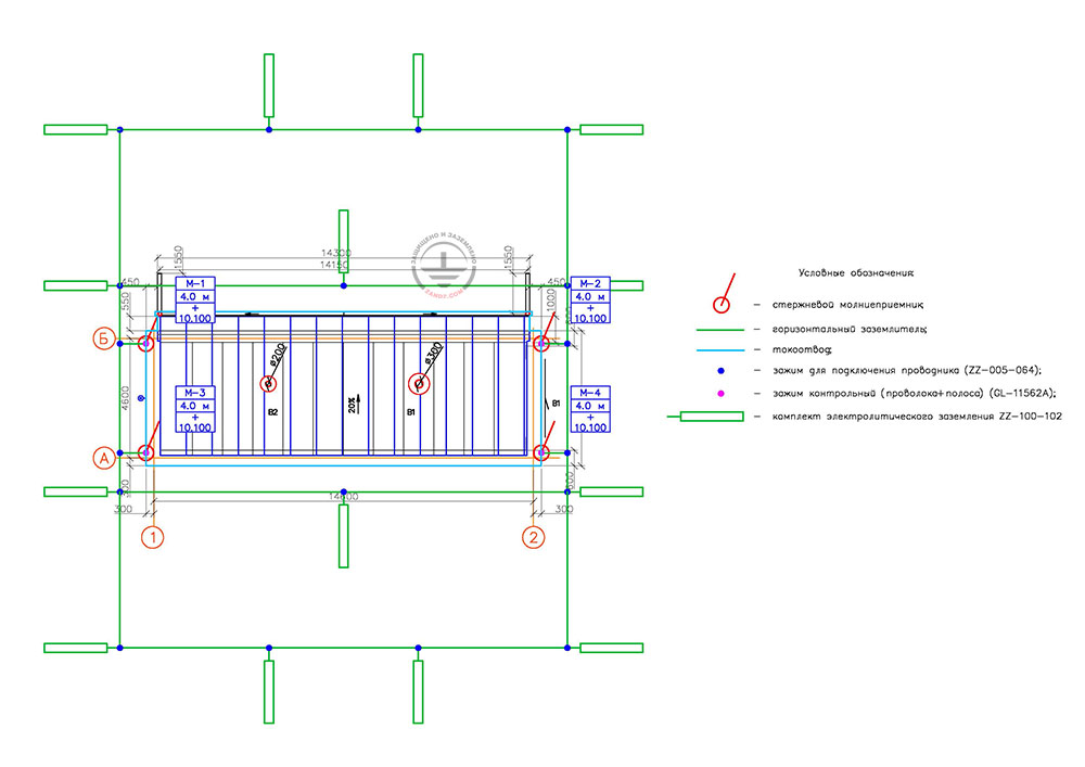
Figure 1. Layout of elements of the lightning protection and grounding arrangement for the instrument building
Условные обозначения - Key
Стержневой молниеприемник - Lightning rod
Горизонтальный заземлитель - Horizontal grounding arrangement
Токоотвод - Current collector
Зажим для подключения проводника - Conductor connecting clamp
Зажим контрольный (проволока + полоса) - Control clamp (wire + strip)
Комплект электролитического заземления - Electrolytic grounding set
Calculation of lightning protection for the instrument building
Calculation of the lightning protection system is made by using the software developed by OAO Krzhizhanovskiy Energy Institute (OAO ENIN).
This software is used in accordance with SO 153-34.21.122-2003, item 3.3.1, and Technical Bulletin No. 25/2009 of the "Roselectromontazh" Association, item 2.
For calculation, the used lightning discharge density to the ground is 4 strikes per sq. m per year.
The results of calculation of the lightning protection performed using software are provided in the table.
| Lightning protection type | 4 lightning arresters 4 m high |
| Protection reliability | 0,9939 |
| Number of strikes into the facility, year | 0,018 |
| Number of blowouts into the facility, year | 0,00011 |
| Period of strikes | once per 56 years |
| Period of blowouts | once per 9091 years |
Calculation of the grounding device for the instrument building
According to the information provided by the customer, the soil is sandy. The estimated soil resistivity is taken to be 700 Ohm ∙ m.
Resistance of the existing grounding system represented by a casing tube is 7.2 Ohm.
The calculation is made using formulas provided in the Grounding Calculation page.
The calculation formulas with the completed data are shown below.
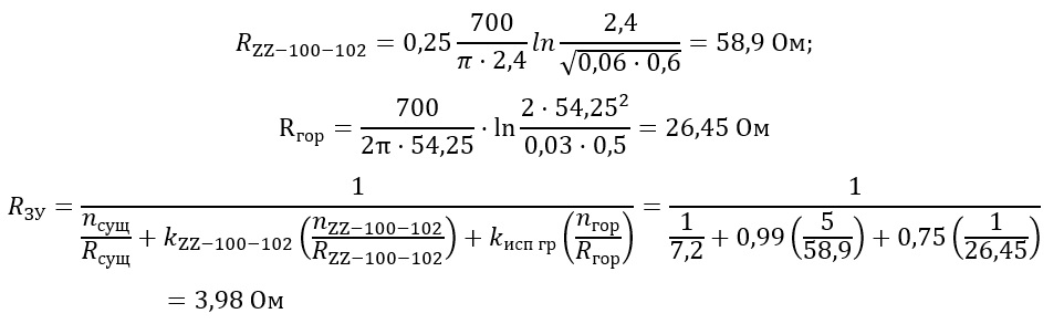
The rated resistance of the grounding arrangement is 3.98 Ohm, which is less than the required value of 4 Ohm.
Ом - Ohm
гор - hr
ЗУ - ED
сущ - ex
Components for lightning protection and grounding of the instrument building
Do you have questions regarding lightning protection and grounding of the instrument building for the earthquake station? Please, contact the ZANDZ Technical Center!
Related Articles: