The production facility is a building intended for industrial companies, where production lines are located and which provide the required conditions for personnel work and operation of the process equipment. The production facility contains basic workshops requiring reliable grounding and lightning protection. Such facilities are classified as conventional according to the regulatory documents and do not imply any special lightning protection options. The ZANDZ Technical Center has received a request to calculate the lightning protection system for a production facility in Samara. The facility had large dimensions. Let us continue with more detailed review of our offered solution.
Lightning Protection of Industrial Facility in Samara
Facility: a production facility in Samara
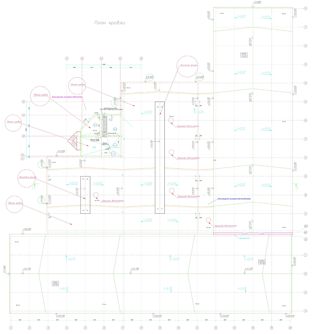
Figure 1. Facility plan.
Task: To perform calculations for the lightning protection system for the production facility in Samara
Solutions to meet the requirements to the lightning protection system of the production facility in Samara:
- The lightning protection is made in accordance with Electrical Installations Code (EIC), Rev. 7, SO 153-34.21.122-2003 "Guidelines for the lightning protection of buildings, structures and industrial infrastructure" (hereinafter referred to as SO) and RD 34.21.122-87 "Guidelines for the lightning protection of buildings and structures" (hereinafter referred to as the RD).
- Grounding arrangement (GA) is necessary to do with a resistance of not exceeding 4 ohms.
- The soil resistivity accepted for computations is 800 Ohm * m.
- The facility belongs to Class III according to RD. The system reliability shall be at least 0.9.
- Lightning protection for the facility is made using 11 x 4 m lightning rods on 3 concrete foundations (GL-21121), 3 x 6 m lightning rods on 3 concrete foundations (GL-21125), and 1 x 8 m lightning rod on 3 concrete foundations (GL-21129) located on the roof.
- A copper-plated steel wire (copper coating thickness of 70 μm min.), d8 mm (GL 11149) is used as a down conductor.
- Down conductors are mounted using the GL-11711 clamp on a flat roof, and GL-11703A on vertical surfaces. The accepted pitch of terminals is 0.8-1.0 m.
- The universal terminal GL-11551A is used to connect rolled products along the length and in joints.
- All metal elements located on the roof must be connected to the main conductor cable with the terminals GL-11545. Stairs and railings are attached using the GL-11514 ring clamp.
- Twenty-six x 6 m vertical steel copper-plated electrodes are used as grounding electrodes. The distance between the electrodes is at least 12 m. The copper-plated steel strip with a cross-section of 30 x 4 mm, combining all vertical electrodes, is used as a horizontal ground electrode. The distance to the facility foundation is at least 1 m. Strip deepening is 0.5 to 0.7 m.
- According to EIC-7 issue, par.1.7.55 - Grounding devices for protective grounding of electrical installations for buildings and structures and the 2nd and 3rd categories lightning protection of these buildings and structures, as a rule, shall be common.
- Resistance design value of the grounding device is 3.97 Ohms.
- If there are concrete-steel constructions, they shall be connected to down conductors/grounding device.
- Connection to the grounding device is carried out using ZZ-005-064 clamps.
Calculation of lightning protection according to SO
| Lightning arrester number | h | Hx | Rcx |
| М-1 | 15,72 | 11,72 | 2,32 |
| М-2 | 15,72 | 11,72 | 2,32 |
| М-3 | 15,72 | 11,72 | 2,32 |
| М-4 | 15,72 | 11,72 | 2,32 |
| М-5 | 15,72 | 11,72 | 2,32 |
| М-6 | 15,72 | 11,72 | 2,32 |
| М-7 | 15,72 | 11,72 | 2,32 |
| М-8 | 15,72 | 11,72 | 2,32 |
| М-9 | 15,72 | 11,72 | 2,32 |
| М-10 | 15,72 | 11,72 | 2,32 |
| М-11 | 15,72 | 11,72 | 2,32 |
| М-12 | 16,97 | 12,97 | 2,05 |
| М-13 | 16,97 | 12,97 | 2,05 |
| М-14 | 16,97 | 12,97 | 2,05 |
| М-15 | 22,21 | 14,21 | 6,59 |
Ground terminal resistance calculation:
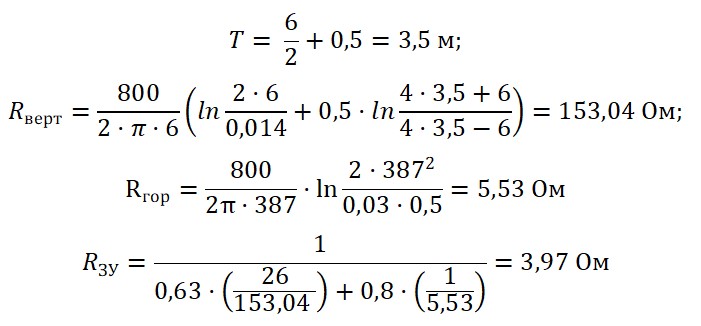
Ом - Ohm
The design resistance of the grounding arrangement is 1,76 ohm.
Figure 2 shows hardware layout.
Table 1 includes the list of required hardware and materials.
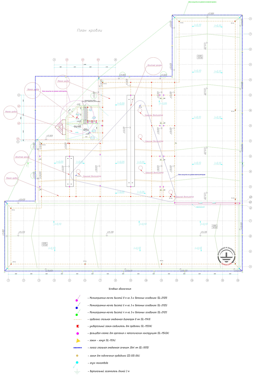
Условные обозначения - Key
Молниеприемник-мачта высотой 8 м на 3-х бетонных основаниях - 8 m lightning rod on 3 concrete foundations
Молниеприемник-мачта высотой 6 м на 3-х бетонных основаниях - 6 m lightning rod on 3 concrete foundations
Молниеприемник-мачта высотой 4 м на 3-х бетонных основаниях - 4 m lightning rod on 3 concrete foundations
Проволока стальная омедненная диаметром 8 мм - Steel copper-plated wire, d 8 mm
Универсальный зажим-соединитель для проволоки - Multipurpose connecting clamp for wire
Фальцевая клемма для крепления к металлическим конструкциям - Flange terminal for attachment to metal structures
Зажим-хомут - Ring clamp
Полоса стальная омедненная сечением 30 х 4 мм - Steel copper-plated strip 30 x 4 mm
Зажим для подключения проводника - Conductor attachment clamp
Опуск токоотвода - Downdrop
Вертикальный заземлитель длиной 3 м - Vertical grounding electrode 3 m
Figure 2. Hardware layout for the lightning protection of the production facility in Samara
Table 1. List of material requirements.
| Position | Designation | Description | Quant. |
| 1 | GL-21121 | GALMAR Lightning rod (4.0 m; on 3 concrete foundations; single-stage wire support; zinc-plated steel) | 11 |
| 2 | GL-21125 | GALMAR Lightning rod (6.0 m; on 3 concrete foundations; double-stage wire support; zinc-plated steel) | 3 |
| 3 | GL-21129 | GALMAR Lightning rod (8.0 m; on 3 concrete foundations; three-stage wire support; zinc-plated steel) | 1 |
| 4 | GL-11149-50 | GALMAR Copper-plated wire (D 8 mm/S 50 mm²; 50-meter bundle) | 17 |
| 5 | GL-11551A | GALMAR Terminal for main conductors connection (painted galvanized steel) | 70 |
| 6 | GL-11711 | GALMAR Flat roof terminal for the conductor cable (plastic, concrete) | 700 |
| 7 | GL-11703A | GALMAR Conductor front terminal providing 15mm elevation of the main conductor over the terminal (painted zinc-plated steel) | 170 |
| 8 | GL-11545A | GALMAR Main conductor rain water gutter terminal (painted zinc-plated steel) | 30 |
| 9 | GL-11514N | GALMAR terminal for fastening the main conductor to a drain pipe (tinned copper strip + stainless steel terminal) | 20 |
| 10 | GL-11562A | GALMAR Control terminal wire + strip (painted zinc-plated steel) for current collectors connection | 7 |
| 11 | GL-11075-50 | GALMAR Copper-plated strip (30 * 4 mm / S 120 mm²; 50-meter strip bundle) | 9 |
| 12 | GL-11075-20 | GALMAR Copper-plated strip (30*4 mm/ S 120 mm²; 20-meter strip bundle) | 1 |
| 13 | ZZ-001-065 | ZANDZ Copper-plated threaded grounding rod (D14; 1.5 m) | 104 |
| 14 | ZZ-002-061 | ZANDZ Threaded coupling | 79 |
| 15 | ZZ-003-061 | ZANDZ Termination | 26 |
| 16 | ZZ-004-060 | ZANDZ Guide head for jackhammer attachment | 21 |
| 17 | ZZ-005-064 | ZANDZ Conductor connection terminal (up to 40 mm) | 36 |
| 18 | ZZ-006-000 | ZANDZ Conductive grease | 8 |
| 19 | ZZ-007-030 | ZANDZ Waterproofing tape | 9 |
| 20 | ZZ-008-000 | ZANDZ Attachment to the hammer (SDS max) | 1 |
Do you have any questions about lightning protection of the production or other facilities? Please, contact the ZANDZ Technical Center!
Related Articles: