Task:
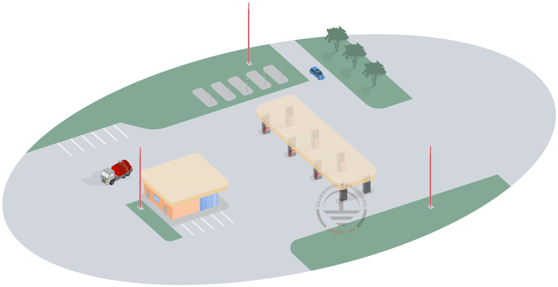
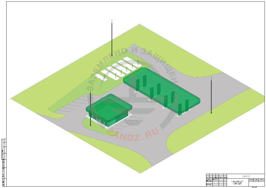
Facility: a gasoline filling station in a conventional design without the car maintenance station.
Area of the facility is 0.5 ha.
A closed gas station pump, a fuel tank farm, and an administrative building with the café are located in the territory.
Soil at the site: rocky sand loam, clay loam.
Soil resistivity is 250 Ohm/m.
Solution:
- 1. According to RD 34.21.122-87 (Table 1), Category I lightning protection is required for GFS (zone A). According to SO 153-34.21.122-2003 (Table 2.1), GFS is classified as a special facility, protection level II, reliability of protection against direct lightning strikes (DLS) shall be 0.99.
- 2. According to RD 34.21.122-87 (item 2.1, item 2.2), protection of buildings and structures classified as category I in terms of lightning protection against direct lightning strikes shall be made using standalone rods or wire lightning arresters. In this case, for standalone lightning arresters, a ground terminal consisting of three or more vertical electrodes at least 3 m long combined with a horizontal electrode is required, and the distance between vertical electrodes being at least 5 m. Minimum cross-sections (diameters) of electrodes are defined in accordance with RD.
- 3. According to item 2.3 of RD, the least allowable distance SSB in the air from the protected facility to the support (current collector) of the lightning rod for buildings and structures not more than 30 m high, at 100 < ρ ≤ 1000 Ohm*m, for artificial grounding arrangements is equal to SB = 4 m.
- 4. According to item 2.6 of RD for the gas vent and breathing stacks equipped with a hood or goose neck, the space above the stack mouth shall be covered by the lightning arresters protection zone to a limit of the height H and radius R: for gases heavier than air, at plant overpressure
5,05-25,25 kPa (0,05-0,25 atm), H = 2,5 m, R = 5 m.
5.To avoid high voltage entry to the protected building or facility along the underground metal utilities (including electrical cables of any purpose), ground terminals for protection against direct lightning strikes shall be distanced from these utilities as much as possible as per the allowed process requirements (item 2.5 of RD).
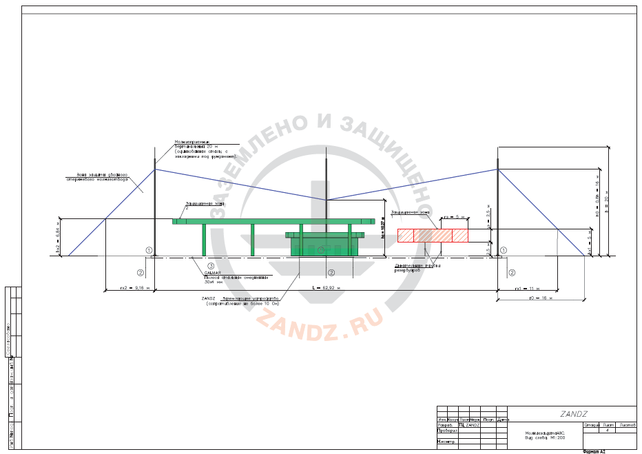
To protect GFS against DLS, three standalone lightning rods (masts) H = 20 m shall be installed.
The ground terminal for each lightning rod consists of three vertical electrodes (threaded copper-plated rods D14; 1.5 m ZZ-001-065 - 2 pcs for electrode).
Ground terminals of lightning rods are interconnected by a copper-plated strip 30 x 4 GL-11075 installed in a trench at the depth at least 0.5 m from the ground surface and attached to the lightning protection bus (DDI PE bus at GFS).
Protection from secondary lightning effects and high voltage is provided by connection of metal pipes, utilities, cable sheaths at the building entry to the earthing circuit.
To protect the equipment and electrical utilities inside the building, we recommend employing a set of measures which allow preventing dangerous overvoltage. DDI contains the surge protection device SDP Class I+II+III PP BCВ TNS 25/100 selected according to a three-phase input to the building and power system TN-C-S or TN-S.
Calculation of the protection zone for a lightning rod according to item 3.3.2.3 of SO 153-34.21.122-2003
h = 20 m is lightning rod height;
h0 = 0,8 х h = 0,8 х 20 = 16 m is protection zone cone height (for protection level 0.99);
r0 = h0 = 16 m is cone radius at the ground level;
L = 62,92 m is distance between lightning rods.
According to Table 3.6 of SO:
Lmax = 4,75 х h = 4,75 х 20 = 95 m;
Lс = 2,25 х h = 2,25 х 20 = 45 m.
hc = (Lmax - L) х h0 / (Lmax – Lc) = (95 – 62,92) х 16 / (95 – 45) = 10,27 m is slack height of the protection zone in the center between lightning arresters.
According to SO:
rx = r0 х (h0 – hx) / h0 – is maximum semi-width lightning protection zone in a horizontal cross-section at height hх;
rcx = r0 х (hc – hx) / hc – is a horizontal cross-section width in the center between lightning arresters at height h which is either less or equal to hc;
1. hх1 = 5 m is protection zone 1 height - protection zone height above breathing pipes;
rx1 = r0 х (h0 – hx1) / h0 = 16 х (16 – 5) / 16 = 11 m;
rcx1 = r0 х (hc – hx1) / hc = 16 х (10,27 – 5) / 10,27 = 8,21 m.
2. hх2 = 6,84 m is protection zone 2 height - gas station pump height.
rx2 = r0 х (h0 – hx2) / h0 = 16 х (16 – 6,84) / 16 = 9,16 m;
rcx = r0 х (hc – hx2) / hc = 16 х (10,27 – 6,84) / 10,27 = 5,34 m.
Calculation of a ground terminal resistance
(Single) vertical electrode resistance:

ρ = 250 Ohm m is soil resistivity;
L = 3 m is vertical electrode length;
d = 0,014 m is vertical electrode diameter;
T – is depth, i.e. the distance from the ground surface to the grounding electrode, m:
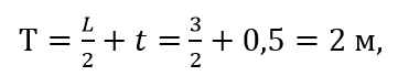
м - m
where t = 0,5 m is electrode top depth.
Resistance of a horizontal electrode:

Гор - Hor Ом - Ohm
where:
ρ = 250 Ohm·m is soil resistivity;
b = 0,03 m is strip width of a horizontal electrode;
h = 0,5 m is a laying depth of the horizontal mesh;
Lгор = 180 m is total length of the horizontal electrode.
Full resistance of a ground terminal:
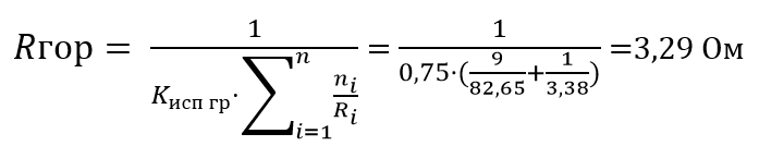
Гор - Hor Исп гр - Util
where:
n is the number of sets;
kutil = 0,75 is utilization ratio.
The calculated resistance of the ground terminal is 3.29 Ohm which is less than rated resistance of 10 Ohm.
List of required materials:
| Item # | Fig. | Designation | Name | Quantity | Unit weight, kg |
| 1 |  |
ZZ-001-065 | ZANDZ Threaded copper-plated grounding rod (D14; 1.5 m) | 18 | 1,9 |
| 2 |  |
ZZ-002-061 | ZANDZ Threaded connecting coupling | 10 | 0,08 |
| 3 |  |
ZZ-003-061 | ZANDZ Kick-off tip | 9 | 0,07 |
| 4 |  |
ZZ-004-060 | ZANDZ Guide head for jackhammer attachment | 4 | 0,09 |
| 5 |  |
ZZ-005-064 | ZANDZ Clamp for connecting conductors (up to 40 mm) | 9 | 0,31 |
| 6 |  |
ZZ-006-000 | ZANDZ Conductive grease | 1 | 0,19 |
| 7 |  |
ZZ-007-030 | ZANDZ Waterproof tape | 3 | 0.442 |
| 8 |  |
ZZ-008-000 | ZANDZ Attachment to the hammer (SDS max) | 1 | 0.48 |
| 9 | 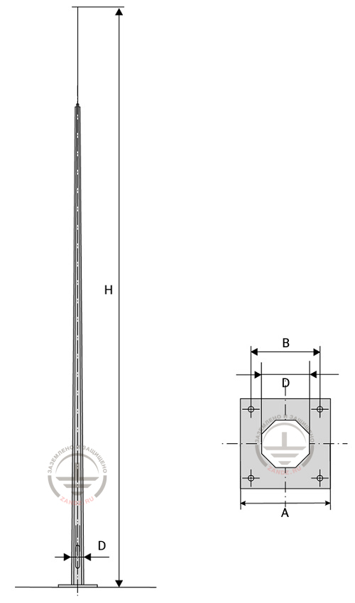 |
ZZ-201-020 | ZANDZ 20 m vertical lightning rod (galvanized steel; with parts embedded under the foundation) | 3 | - |
| 10 |  |
GL-11404 | GALMAR Inspection pit | 9 | 2,6 |
| 11 |  |
GL-11075 | GALMAR copper-plated steel strip 30х4 mm | 190 | 0,98 |
| 12 | 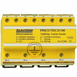 |
LE-373-960 | LEUTRON Surge protecting device (SDP) PP BCD TNS 25 / 100 | 2 | - |
Appendix: design in DWG and PDF formats
Need a design of earthing and lightning protection? Order now by contacting ZANDZ Technical Center!
Related Articles:
