The fifth webinar of a series "Grounding and lightning protection: issues and problems arising in the design"
(was held on November 19, 2014 at 11:00 MSC)
We recommend streaming of "720p" quality in a full-screen mode
Most publications of informational character offer to calculate ground electrode systems on the base of utilization ratio.
The matter comes down to the parallel addition of ground resistances of elementary electrodes (vertical rods or horizontal buses) and with the further division of the result by the mentioned ratio. As a rule, a specialist cannot assess the accuracy of the calculation, since the value of the shielding factor extracted from the reference tables, is much less than one, and the origin of the charts is not disclosed by the authors of the reference books.
The theory of grounding devices calculation at a constant or slowly changing current had been well developed long time ago. It is completely identical to the theory of calculation of fields of electrostatic charges and uses the methodological basis developed in the beginning of the last century. In fact, the problem comes down to the determination of the grounding device potential, taking into account all the current sources in the ground. The principle of superposition and the method of mirror reflections, thanks to which it is possible to consider the influence of the boundary soil- air and the layered soil structure, is very effective.
A rigorous solution of most practical problems of course requires the use of computer technology, development of algorithms and software. These things are difficult to learn during a short workshop. Therefore, the analysis of the fundamental properties of grounding devices and assessment of their quantitative characteristics, which can be performed in lay terms, is regarded as of paramount importance. It is supposed to assay the effect of the depth of electrodes placement, the effect of two-layer soil, the shielding effect in a multi-electrode construction.
Wherever possible, methodological approaches to assess ground resistance manually, are offered; the limits of application of semi-empirical calculation relations are set. Special attention will be paid to the calculation of ground resistance of reinforced concrete structures, where neighbouring metal reinforcement elements are used as the grounding electrodes.
In conclusion, it is expected to briefly highlight the methodology of calculating impulse responses of ground electrode systems, in relation of which there recently appeared a lot of speculative solutions.
Webinar text. Page 1
Estimated reading time: 1 hour 20 minutes
Calculation of grounding devices
Расчёт сопротивления заземления – grounding resistance calculation
Семинар пятый – the fifth seminar
Проф. Э.М. Базелян – Professor E.M. Bazelyan
ОАО «Энин» Москва – "Enin" JSC, Moscow
Good afternoon or good morning. I do not know where to start, because, perhaps, we are all in different time zones. But I am happy to talk with all of you here in the ZANDZ project studio. I'm sitting here with my good assistant Nadezhda. And frankly speaking, the seminar, the name of which you see here, put me into a mental tremor and I could not sleep at night and was thinking of how to make it interesting and clear for you. The fact is that in any technology there are applied branches which are unfortunate and unlucky. Here it's the methodology of design calculations, methodology of engineering bindings. It goes somewhere away from the main road and it's not clear how it went down this road, and why we suddenly get what we get. I believe that this is one of those happy and unfortunate industries. It is a branch concerning the calculation of ground resistance.
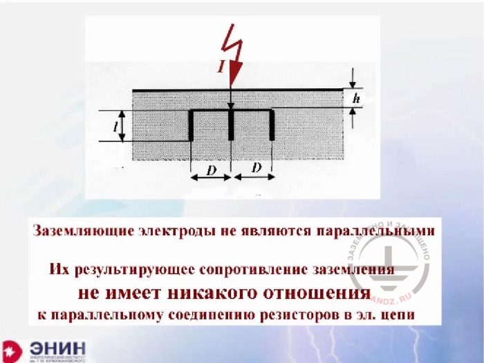
Ground electrodes
Заземляющие электроды не являются параллельными – Grounding electrodes are not parallel
Из результирующее сопротивление заземления не имеет никакого отношения к параллельному соединению резисторов в электрической цепи – their resulting grounding resistance has absolutely no concern to the parallel connection of resistors in an electric circuit
The fact is that those traditions that have arisen here they come down to the fact that ground electrodes that lie in the ground, for some reason began to be considered, it began about 100 years ago, considered as parallel electrodes of electric circuit. For some strange reason, calculation of that ground resistance was carried out as calculation of parallel branches in the circuit, considering that each electrode has some specific ground resistance, and in total they should in parallel. You can see it on this formal image that this is not so. Because the circuit elements are considered to be parallel if their beginnings and ends are connected. In fact the beginnings of ground electrodes are connected, but the ends are not. Each electrode takes part in current spreading in the ground independently, however interacting with all the other electrodes. The theory of parallel and cascade connection of the circuit elements has absolutely no concern to this thing. Neither formal, no real concern. Well, when they saw that this was the case, they began to introduce all sorts of correction factors, the so-called utilization rates. And this practice of using correction factors still exists, though it could not and cannot bring to any good result.
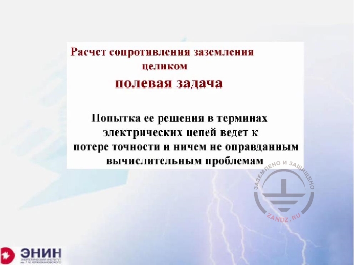
Calculation of ground resistance
Расчёт сопротивления заземления – целиком полевая задача – Calculation of grounding resistance is a clearly field task
Попытка ее решения в терминах электрических цепей ведет к потере точности и ничем не оправданным вычислительным проблемам – An effort to solve it in electric circuits leads to the loss of accuracy and unjustified calculation problems
What is the calculation of ground resistance? Formally, it is a pure task of calculating electric fields and any attempt to solve it in a different way results in confusion or inaccurate results, or to a heap of correction tables and, which must be used. I would like to show you today how a modern engineer should solve such tasks, an engineer who has modern computer technology in his hands and who generally knows what he needs. I'll try to do the best I can. Of course I realize very well that it would be better to have such a conversation in person, with a board in front on which it would be possible to write basic correlations.
The theory of the DC electric field
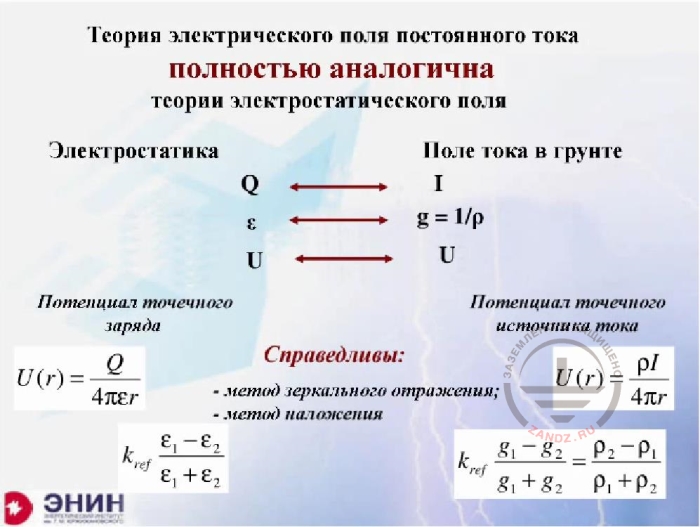
Теория электрического поля постоянного тока полностью аналогична теории электростатического поля – The theory of the DC electric field is totally similar to the theory of electrostatic field
Электростатика – electrostatics
Поле тока в грунте – current field in the ground
Потенциал точечного заряда – Potential of point charge
Потенциал точечного источника тока – Potential of point current source
Справедливы: метод зеркального отражения; метод наложения – Fair: method of mirror reflection; overlay method
If we talk about ground resistance calculation theory, this theory was entirely developed at least a century ago. Because the theory of calculation of direct current fields or slowly changing current, it fully corresponds to the electrostatic field theory. The analogy is absolutely perfect here. A charge is a current analogue. The dielectric capacity of environment is an analogue of conductivity or analogue of unit divided by soil resistivity. Regarding the voltage, it is in both cases. For this reason, all the remaining correlations that are used in the electrostatic field theory. All of them, without exception, working in the DC field theory, which determines ground resistance. In particular, the basis for all calculations in the theory of electrostatic fields is the potential of a certain point on the Q charge, known from the school formula, the formula from a school course. And the same analogue is in the DC field theory. But the current appears here instead of the charge, and instead of dielectric conductivity-the epsilon- we have one divided by p, specific conductivity of soil. And all the correlations we have here, they work too, and first of all the superimposing principle according to which an electric field in a linear environment from the sum of charges is the sum of these fields from every charge separately. Similarly, there is theory - the potential of some current from the sum of currents is the sum of potentials of every current separately. Finally, there is a method of mirror reflections, which allows removing the boundary between two environments with different dielectric conductivity. This is done in dielectric environment. Exactly the same thing is done in the ground, when one soil has a resistivity p1 and another soil has a resistivity p2. In particular, this reflection works in case, when the second environment is air. The resistivity of which is infinitely great. In this case, the formula that appears here shows what you have obtained; the reflection coefficient is exactly equal to one. And that means in order to remove the boundary between ground and soil; it is necessary to reflect the current, absolutely not changing the value and not changing its direction. If to gather it all together, we'll get this kind thing. It will turn out that if you take the reference book on calculation of electric induction, then any formula in this reference book will fit not only the calculation of the elastance, it will fit calculations of ground resistance in general. We only need to do one thing. We need to change the dielectric conductivity epsilon to the specific unit, divided by soil resistivity, and the formula won't give you ground resistance but grounding conductivity. In order to obtain resistance, the unit must be divided by this value. Actually the ideology of all calculations is as is. And it would not be necessary to talk about it if not one circumstance.
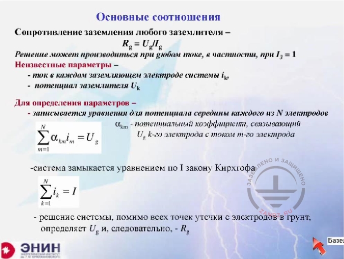
Basic correlations, grounding resistance
Основные соотношения – Basic correlations
Сопротивление заземления любого заземлителя – grounding resistance of any ground electrode system
Решение может производиться при любом токе, в частности при – the solution can be carried out at any current, in particular at the current of …..
Неизвестные параметры – unknown parameters
- ток в каждом заземляющем электроде системы …- current in every grounding electrode of ….system
потенциал заземлителя…. - ….ground electrode potential
Для определения параметров – to define parameters –
записывается уравнение для потенциала середины каждого из N электродов - an equation for the potential of the middle of every of N electrodes is written
Система замыкается уравнением по I закону Киргхофа – the system closes with the equation on the I law of Kirchhoff
Решение системы, помимо всех точек утечки с электродов в грунт, определяет U, и, следовательно, R - Solution of a system, besides all points of current leakage from the electrodes to the ground, determines U and consequently R
It is for this reason that we should not rely on reference books on calculation of capacities and rely more on ourselves. These are the rules of the calculations. It is easy to understand these calculations. Imagine you have a grounding device, which consists of some number of electrodes. You apply a current to the system and calculate the voltage which will be on the ground electrode. If you divide this voltage by the current that flows from the ground electrode, you will get grounding resistance. That's it, the task in fact comes down to the following, to calculate voltage on the ground electrode from the current which flows through its electrodes. That's what should be done. How to count? All calculations I will talk about, they are held in a linear environment. And due to the fact that they are held in a linear environment, there is a simple relation between the current and the potential that this current creates. This correlation is expressed via the coefficient, in my case; it is alpha coefficient, which connects the ground electrode potential with the current, which flows over the specific element. And if I know that potential element for each conductor, which is in the ground and I know the current that flows through the conductor, I have the sum of these products. A number of members in the amount correspond to the number of electrons. It will be equal to the unknown voltage. If you look at how many unknowns you have, it will turn out that the current of each electrode is unknown, and in addition, the voltage that is created in all these electrodes is unknown. Therefore, the number of unknowns will be one more than the number of equations. Therefore, in order to close the system, it is necessary to remember this kind of thing, that according to the first Kirchhoff's law, the sum of all currents through the ground electrodes is equal to the current which I am sending to the ground electrode system.
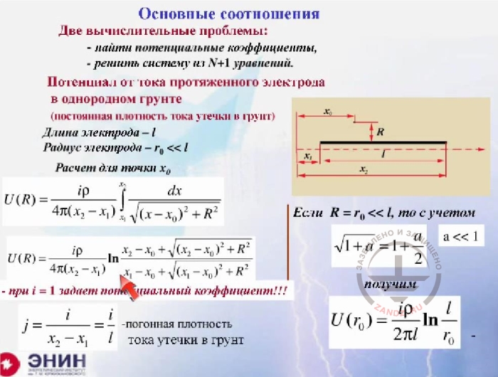
Basic correlations, two computational problems
Основные соотношения – basic correlations
Две вычислительные проблемы - two computational problems
- найти потенциальные коэффициенты – find potential coefficients
Решить систему из N + 1 уравнений – solve the system of N+1 equations
Потенциал от тока протяженного электрода в однородном грунте (постоянная плотность тока утечки в грунт) – potential from the current of an extended electrode in a homogeneous ground (constant density of current leakage to the ground)
Длина электрода – l – electrode length, l
Радиус электрода – electrode radius
При i =1 задает потенциальный коэффициент = at i=1 sets a potential coefficient
Погонная плотность тока утечки в грунт – linear density of current leakage to the ground
It will give voltage on these electrodes. And if I divide this voltage by current, which I consider as the initial value, I can set any current, even 1, I will get ground resistance, i.e., the task comes down to solving a system of linear algebraic equations, and the number of these equations corresponds to the number of grounding electrodes in the circuit, plus one more equation. That is, we are talking about a large number of equations. However, it's not a problem for modern computers. There is software for solving equation systems, like any typical software, anywhere, even in Matlab. The question is different. How to properly and correctly calculate these potential coefficients. And the matter actually comes down to the calculation of the potential coefficients. There is one rather pleasant circumstance that's associated with the following. The electrodes, with which we work, arranging ground electrode systems, are usually of the same type. They are either rod, the length of which is much greater than their diameter. Or tapes, the length of which is again much greater than the cross-sectional dimension. And in order to calculate the potential coefficient for such a conductor, with the length l, and with the radius much smaller than this length. We can use the principle of superposition and make an elementary calculation, which is shown on this poster. In the result we get an expression which connects the current which flows through the element, and the potential at point R, which produces this very current. This expression is quite standard and typical. It is suitable for any extended conductor, for any conductor you want. And it is suitable for any computational point, even for the point which is located on the surface of the conductor. And if I find the potential on the surface of the conductor, that is here on the surface. I will find voltage on that conductor, and if I divide this voltage is by the current, then I get an expression for the ground resistance of the extended conductor. Here, for example, this expression is written in a homogeneous infinite environment, which has no boundaries between the air and the ground, this border is very far.

Equations for the electrodes
Поскольку подавляющее большинство практических конструкций заземлителей состоит из протяженных шин или вертикальных стержней, задача методологически решена – As the majority of practical constructions of ground electrode systems consists of extended buses or vertical rods, the task is methodologically solved
Остается записать уравнения для всех электродов и решить полученную систему любым известным методом или с помощью любой доступной программы – It is only left to write the equations for all electrodes and solve the received system in any known method or with the help of any available software
Никаких параллельных соединений проводников, схем замещения с резисторами и ввода коэффициентов использования для расчета сопротивлений заземления не требуется – no parallel connections of conductors, equivalent circuit with resistors or entry of use coefficients for calculation of grounding resistance are required
Далее речь идет только об упрощении вычислений – Further we will talk only about simplification of calculations
The methodology is all set out. In fact, nothing else is required. It is enough to have that very formula of the potential coefficient, which I wrote. It is enough to write this system of equations and solve it with the help of any computer at your disposal.
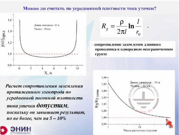
Can it be calculated by the average density of current leakage?
Можно ли считать по усредненной плотности тока утечки? – can it be calculated by the average density of current leakage?
Длина электрода 10 м, радиус 10 мм - length of the electrode is 10 m, radius – 10 mm
Сопротивление заземления длинного проводника в однородном неограниченном грунте – grounding resistance of a long conductor in a homogenous unlimited ground
Расчет сопротивления заземления протяженного электрода по усредненной погонной плотности тока утечки допустим, поскольку он завышает результат, но не более, чем на 5-10 % - the calculation of grounding resistance of a lengthy electrode with the equivalent linear leakage current density is acceptable, because it skews the result upwards.
And we now have a server dropdown; we lost picture and sound all at once. So the first question that arises is as follows. I have shown you an expression for the potential coefficient, which is suitable for any tape or any rod which is located in the ground. The question is, how precise the solution that is written there is. The question is as follows. The solution obtained by the supposition that the density of the current which flows from the rod into the ground, is completely unchanged over the entire length of the rod. It is, generally speaking - a stretch, because in fact, If I take a rod and accurately calculate how the current flows down from it, I will get this kind of thing. The current which flows down from the rod, is almost the same on its most part. As for the ends of the rod, here the current is quite unstable. The closer it is located to the end of the rod, the denser it becomes. In the result of the current distribution along the rod, it turns out to be uneven. It is shown here as a black stripe. And the question is whether it is possible to make something average instead of this distribution. A perfectly accurate field computer calculation shows that the error from this simplification is totally insignificant. Please look, here you see the calculation that is made for a perfect case and the calculation which is made for the average case. The margin of error is only 5%. The error of 5% is the error that can be ignored when holding any engineering calculation. And so we can assume that for any rod you want, even ten or fifteen-meter rod or for a twenty-meter tape which you put into the ground.
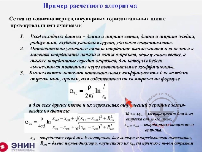
Example of calculation algorithm p. 1-3
Пример расчетного алгоритма – example of calculation algorithm
Сетка из взаимно перпендикулярных горизонтальных шин с прямоугольными ячейками – Mesh of mutually perpendicular horizontal buses with rectangular cells
-
Ввод исходных данных …..- Initial data entry- length and width of the mesh, length and width of the cell, radius of buses, depth of laying into the ground, electrical resistivity
-
Arrays of coordinates of beginning and end of cuts forming the mesh and also coordinates of middles of cuts for which the potential will be calculated via potential coefficients, are calculated and introduced relatively to the conventional beginning of coordinates
-
Values of potential coefficients for each bus cut are calculated, what is interesting, for an own cut current with the following formula
and for all other currents and their mirror reflections on the border ground-air with the formula
here (альфа) – coefficient for k cut from m current
xx – coordinates of ends of m cut
x – coordinate of the middle of k cut, for which the potential is defined
R – length of a perpendicular put by their x to the right line with m cut
Now, how to imagine a calculation that should have been done by an engineer who has a computer and who wants to calculate the ground electrode system which he needs to design. The first thing he has to start with is to enter the coordinates of all the electrodes, which are part of the ground electrode system. It is possible to set these coordinates from any computable point in any coordinate system, there is absolutely no difference. When you enter these coordinates, at first you enter the coordinates of the beginnings and then of the ends of all electrodes. You automatically get the length of the electrodes and you set the radius of the electrode and after that you calculate a potential coefficient. For own current - the potential factor will be as follows (first formula). And for all the neighbouring currents, it will be as follows (second formula). Where are all geometric dimensions - are the sizes of the beginning and the end of any electrode. R - is the distance between the electrode that you have and the electrode, where you calculate the potential. A p - is the electrical resistance of soil. When you do all this, you will get a system of equations, about which I've been speaking. Such a system of equations.
Next Page >>
Slides 10 to 18
Related Articles:
