The fifth webinar of a series "Grounding and lightning protection: issues and problems arising in the design"
Webinar text. Page 2
Example of calculation algorithm, p. 4-8
EN
Пример расчетного алгоритма
4.
5.
6.
Базелян Эдуард Михайлович
7.
8.
Ориентировочное время расчета сетки из 25х25 ячеек…
RU
An example of calculation algorithm
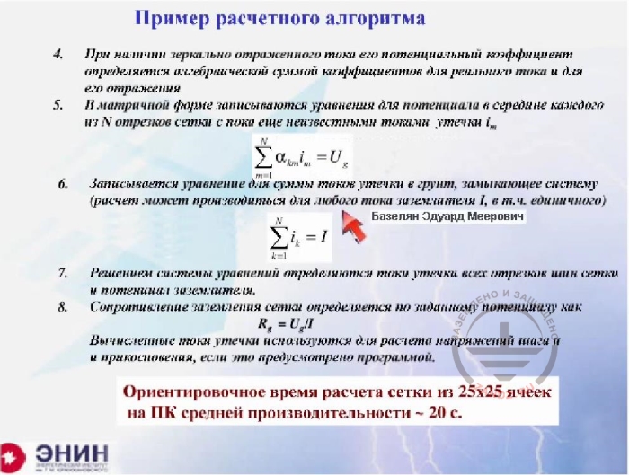
4. If a mirror reflection of current is present, then it potential coefficient is determined by an algebraic sum of coefficient of the real current and its reflection
5. Equations are written in a matrix notation for the potential in the middle of each of N sections with yet unknown leakage currents Im
6. An equation is written for a sum of leakage currents in the ground that short circuit the system (the calculation can be made for any ground electrode system current I, including a stand-alone system)
Prof. Edward Bazelyan
By solving the equation system, leakage currents of all mesh bus sections and the potential of the ground electrode system.
The mesh grounding resistance is determined by the nominal potential as
Rg=UglI
The calculated leakage current values are used to calculate the step and touch voltages if the software provides for this.
The average time needed to calculate the mesh of 25x25 cells using a mid-range PC is 20 c.
And here's an additional equation for the current. When you solve it all together, you will find the unknown voltage, divide it by the current, for which you've made the calculation and get the result. Which system of equations is used in real life? This system. I took a grounding loop of a substation at a fairly large plant. This is approximately 250 meters long and 250 meters wide. And I've arranged square cells with a step of 10 meters in the loop. It turns out I need about 800 electrodes. So this is the number of equations I need to solve. How long will it take for a simple PC to solve them? Approximately 20 seconds. After 20 seconds I’ll get an answer. All in all, there is nothing more to do here. And we can end our webinar, right?
Mirror reflection on the ground-to-air border
RU
Как это делается
Полезные детали
Отраженный электрод
1. Зеркальное отражение на границе грунт-воздух
За счет отражения длина электрода удвоилась
Но поскольку реально работает…
Сопротивление заземления вертикального стержня
EN
How it’s done
Useful tips
Reflected electrode
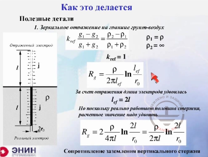
1. Mirrored reflection on the air-to-ground border
The length doubles due to the reflection
But as only half the rod actually works, you need to double the calculated value
Vertical ground rod grounding resistance
But you always want to make things even easier and you always want to consider techniques that empower you to make assessments. And I want to make an overview of these techniques and show you how you can get ratios which you are quite familiar with. And here's the first option. Here's the ground level view of an electrode (left) having a length l. What should I do in this case? It's very simple. To remove that border so that you can assume the electrode is in a homogeneous soil with no air on top, you should make a reflection for the electrode with the following reflection factor. Considering that the specific air resistance is infinitely large, this is the ratio. Then it turns out that there is an electrode of a double length — here it is. And all you need is to substitute values in the formula. And you need to substitute only a single value. You need to substitute the actual length with the doubled length. That is, you must substitute l with 2l. If I substitute this value with this one here under the logarithm, and substitute it in the denominator, then I’ll get the following expression (see the formula below), but without 2. Now, where did I get this 2? This 2 is taken from here. After all, not the whole electrode is working but half of it, and therefore, the grounding resistance will be twice more than that provided by the formula.
Consideration of the electrode upper end depth, rod
RU
2. Учет глубины верхнего конца электрода
Вертикальный стержень
Потенциал от собственного тока
Потенциал от тока отраженного электрода
Полный потенциал
Отраженный электрод
Реальный электрод
EN
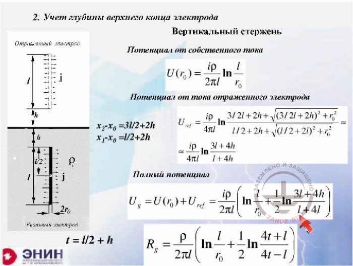
2. Making allowance for the depth of electrode’s top end.
Vertical rod
Electrode’s own current potential
Reflected electrode’s current potential
Total potential
Mirrored electrode
Actual electrode
Next, let's overview a more important result. A vertical electrode has been driven in a small trench at a depth h, not at the ground surface. In this case, you obtain this kind of reflection: here's the real electrode and here's a reflected electrode used in order to remove the border. And they are at a distance of double height h from each other. All the formulas are working again, and these are the same formulas. The electrode’s own potential remains unchanged, and here it is. And we should add the potential of the reflected electrode bearing in mind that the distance between the beginning of this piece and this point is equal to this value. Here it is. And the distance between this point and the actual calculation point of a real electrode is this. This is a simple geometrical arrangement. As a result, the total potential is the sum of the electrode’s own current potential and the potential of the reflected current. This total potential is recorded here. What we have to do is to divide the total potential by the current, and we'll obtain an expression for the grounding resistance. I specially wrote the grounding resistance expression the way it is usually written in handbooks. The handbook writers use this value, i.e. they input some calculated parameter t equal to half the length plus depth h. This way they get a ratio included in absolutely all handbooks.
Consideration of the electrode upper end depth, bus
RU
Учет глубины верхнего конца электрода
Горизонтальная шина
Потенциал от собственного тока
Потенциал от отраженного тока
Полный потенциал
Отраженная шина
Реальная шина
EN
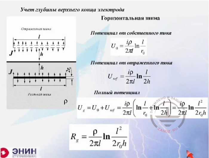
2. Making allowance for the depth of electrode’s top end.
Vertical bus
Bus own current potential
Bus reflected current potential
Total potential
Reflected bus
Actual bus
Now, exactly the same operation can be carried out if you have a buried bus having a length l, here it is, buried at a depth h. Here, this is the bus own current potential, and here is the potential of the reflected bus current. If I sum them up, I will get this expression. You just need to make an algorithm. I.e. you can obtain formulas commonly included in handbooks very simply if you remember two things. Memorize the expression for the potential ratio and the expression for the current, which is reflected in the air, as the reflection occurs with the correction factor identical to one.
Effect of adjacent ground electrodes
RU
Влияние соседних заземляющих электродов
Простейшая ситуация – неограниченная однородная среда,…
В силу симметрии все токи утечки одинаковые
i=I/3
Потенциал от собственного тока -
Потенциал от каждого из соседних электродов -
Полный потенциал электрода -
Длина электродов = l
EN
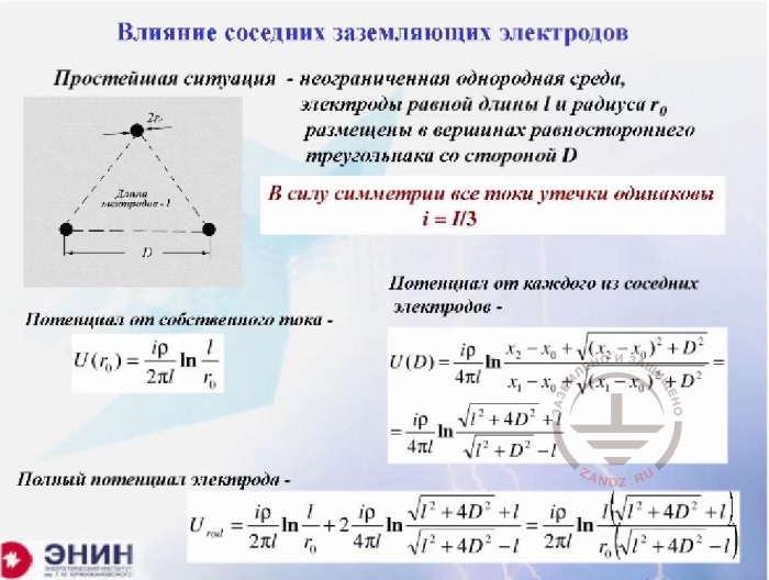
The effect of adjacent ground electrodes
A simplest situation – an unlimited homogenous media, the electrodes have equal length l and a radius r0 arranged in the vertices of a equiangular triangle with side D
Due to the symmetry, all leakage currents are the same
i=I/3
Own current potential
Potential from each of the adjacent electrodes -
Total electrode potential
Electrode length g= l
Now here comes a question. Imagine you have a number of electrodes not too far from each other. For example, I have drawn the simplest situation in the picture, which is here. Look, I have three electrodes in a homogenous soil and, to make things simple, there's no air-to-ground border. And these electrodes are arranged at the vertices of an equilateral triangle. Now, each electrode is symmetric with respect to the rest of electrodes. Thus, you do not have to solve the problem of current. The current, which flows from the electrodes at their full symmetry, will be distributed evenly among the three electrodes, so three currents will be drained from each electrode. Again, I want to see what grounding resistance I will have in the case when there are three electrodes. Once again, the potential of the electrode's own current is defined by the following expression. And the potential of the neighboring electrodes is determined by this expression, where distance D is used instead of distance R.
Grounding resistance with consideration of cross-effect of electrodes
Сопротивление заземления с учетом взаимного влияния электродов
Без взаимного влияния было бы
Коэффициент использования
Расстояние между электродами, м
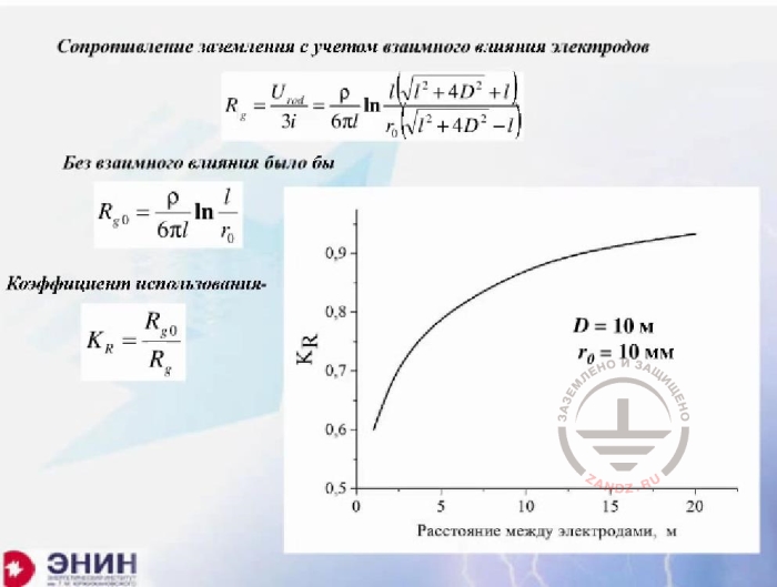
Grounding resistance with consideration of cross-effect of electrodes
Without cross-effect
Utilization ratio
Distance between electrodes, m
Compare the expression I have written below, the one that gives me the grounding resistance of this system, with the expression that would have appeared if I considered that each electrode acts as an independent one. In this case, I would have obtained three times smaller grounding resistance compared to an individual electrode. So, this is the second expression. Now, if I divide this one by this one (the first formula by the second one), I’ll get that damn utilization ratio, which is included in all handbooks. Look what I get. This utilization ratio depends on the distance between the electrodes, and the calculation I've made is as follows. The length of the electrodes is 10 meters each, the radius of electrodes is 10 mm each, and the distance between electrodes is changing. The smaller this distance, the smaller becomes the utilization ratio. At a distance of 1 m, the utilization ratio is somewhere at the level of 0.6. In other words, I should get a figure, and then divide it by the utilization ratio, and as a result the calculated value would double. If I make a calculation and then enter a correction into this calculation that changes the calculated value by half, then a reasonable question arises: why do I calculate at all? It turns out that I do not calculate very well, not exactly right.
Simplifying the calculation of reinforced concrete piles and beams grounding resistance
RU
Для практики полезна оценка ….
Если D….
В случае одиночного стержня…
Откуда…
- полное соответствие эффективному радиусу расщепленного провода
- справедлива для любого числа стержней n
Существенное упрощение расчета сопротивления заземления ж.б. свай и балок!!!
EN
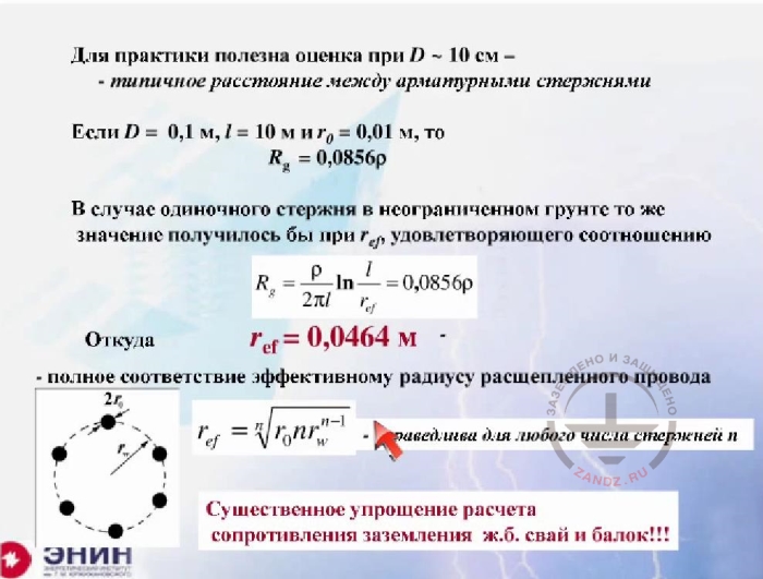
For practical purposes, it is useful to evaluate at D~10 cm – a typical distance between reinforcing bars
If D=0.1 m, l=10 m and r0=0.01 m, then Rg=0.085
In case if one rod is used in an unlimited soil, you would get the same value at ref that satisfied the following correlation:
Thus, ref = 0.0464 m
- the full correspondence to the radius of a multiple conductor
- true for any number of bars n
A significant simplification of grounding resistance calculation for reinforced concrete piles and beams!!!
But the following thing is even more important. Let's assume the distance between the ground electrodes is very small, for example 10 cm. Where can such a distance really appear? In other words, you probably won't find an idiot among engineers who would drive the rods into the soil at a distance of 10 cm from each other. That's right, there are no such engineers. But you have the reinforcement bars of your foundation. According to Russian laws, the foundation rebars should be used as ground electrodes, and this is a solution by default. And this standard solution is based on the following. This method is based on a huge work carried out by the Reinforced Concrete Research Institute, which has shown that when the concrete gets into the soil it absorbs moisture. And after a while, the concrete does not differ from the soil in which it lies. So you have reinforcing bars in the concrete at a distance about ten centimeters. Let's see what happens if you calculate the utilization ratio in this case. And I've calculated, for example, as follows. The reinforcing rods are 10 meters long, their radius is 1 cm, and the distance between the rods is about 10 cm. In this case, the utilization ratio is about 0.25. And it turns out that the result that you'd get would have to be corrected by more than 2 times. But one thing is interesting. It's really interesting. I’ve made a calculation using a distance of 10 cm between the rods, between three rods actually. I made the grounding resistance calculations correctly, and I got this value. This is the factor, which must be multiplied by the soil resistivity. And now I'm asking a question. What ground rod radius should I have to replace all the three electrodes and receive exactly the same value? I’ve solved this problem, and it is easy to solve. It turns out that in this case, the radius is 4.6 cm. And what is 4.6 cm? This is the radius of the circle where the rods are installed at an angle of 120 degrees. So the following thing happens. It appears that any number of reinforcing bars put at equal steps on a defined circle can be replaced with a single rod with a radius equal to this value (that's my final formula). This formula, which I have written here, corresponds to the formula used for the calculation of an equivalent radius of the split wire applied on a power line to calculate the capacitance. So you may not worry about complex calculations for reinforcing piles, for example. You need to know how many rebars are in them and an average radius along which these rods are distributed. Put this in the calculation formula, receive the equivalent radius and further assume that you have no piles at all, just a single rod with such a radius. And you can use the grounding resistance of this foundation pile with no huge mistake.
Consideration of uneven distribution of leakage current over ground electrodes
RU
Всегда ли надо учитывать…
Для крайнего электрода -
Для среднего электрода -
EN
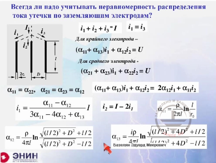
Do you always need to consider the uneven distribution of leakage current through ground electrodes?
For the outermost electrode -
For the center electrode -
Now let's get to a more difficult task. This task is as follows. Imagine you have rods arranged asymmetrically. Look, I have a set of three electrodes — one, two and three. The currents in these electrodes will be identical, but for the central electrode, the current will be actually different. And the question is: can this system be calculated and how? It turns out there is no problem here because the sum of currents in all three rods should be equal to the total current. Here is the current of two outermost rods. And now I write down an expression for the potential of the central rod through the potential coefficients of the outermost rods and its own potential. And for the central rod, I also do it using its own potential and the potential coefficients of neighboring electrodes. I have already shown how to calculate all these potential coefficients, they were already written here. As a result, I get the following thing.
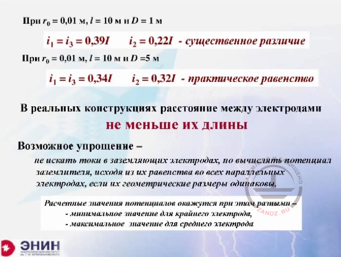
The distance between the electrodes is not less than their length
RU
Когда r0=0.01 m, l=10 m and D=1 m
Когда r0=0.01 m, l=10 m and D=5 m
В реальных конструкциях расстояния между электродами
Не меньше их длины
Возможное упрощение -
Не искать токи в заземляющих электродах, но вычислять потенциал заземлителя, исходя из их равенства во всех параллельных электродах, если их геометрические размеры одинаковы.
Расчетные значения потенциалов окажутся при этом разными -
- минимальное значение для крайнего электрода
- максимальное значение для среднего электрода
EN
When r0=0.01 m, l=10 m and D=1 m
When r0=0.01 m, l=10 m and D=5 m
In real-world structures, distances between electrodes
Not less the their length
Possible simplification -
Do not search for currents in ground electrodes but calculate the potential of the grounding electrode system proceeding from their equality in all parallel electrodes if their geometrical size is the same.
Calculated values of potential will be different in this case -
- minimum value for the outermost electrode
- maximum value for the middle electrode
The result is that the unevenness of the current distribution is dependent on the distance between the rods, and it is quite natural. Let’s assume these 10-meter rods are at a distance of 1 m from each other, as shown in the top line. If I write the expressions for the 10-meter rods at a distance of a meter, the load will be significantly different. Look, 40% of current will come to each outermost rod, and 20% of the current come to in the central rod. But if I start moving the rods apart at a distance, which is used in practice, for example, I take a distance about 5 meters between 10-meter rods, then my current load will become almost the same in all the rods.
<< Previous Page
Slides from 1 to 9
Next Page >>
Slides from 19 to 22 + questions and answers session
Related Articles:
 Lightning protection of residential and public buildings - answers to frequently asked questions in the design

 Lightning Protection of Large Territories: Parks, Grounds, Plant Territories. Page 1
 Lightning Protection of Large Territories: Parks, Grounds, Plant Territories. Page 2
 Lightning Protection of Large Territories: Parks, Grounds, Plant Territories. Page 3