The fifth webinar of a series "Grounding and lightning protection: issues and problems arising in the design"
Webinar text. Page 3
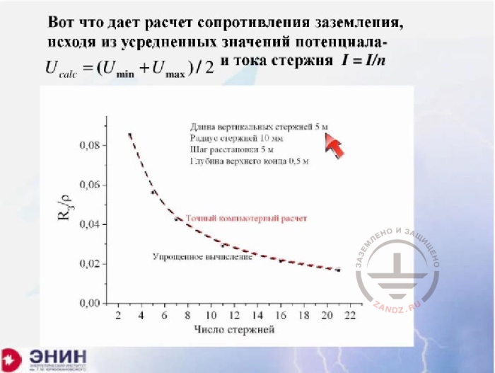
Calculating earthing resistance based on the average values of the potential
And then I can consider that the task has been simplified, assuming that the same leakage current is present in each ground rod, and only taking into account the cross-effect of the rods. The error we obtain here is so small that an exact calculation (red line) and an approximate calculation (black line) are virtually not separated at this chart.
Large area ground loops
RU
Контуры заземления большой площади
- как правило это сетки из…
- Эмпирическая формула Оллендорфа-…
S – площадь сетки, L- длина полос сетки
Формула обоснованно не учитывает…
Длина сетки 100 м
Ячейки 10х10 м
Формула Оллендорфа-Лорана
Ширина сетки, м
EN
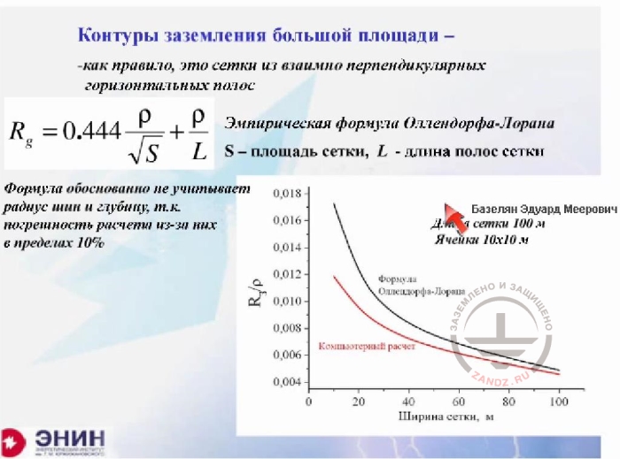
Large area ground loops
- as a rule, these are meshes made from mutually perpendicular horizontal tapes
- The empiric Ollendorf-Laurent formula
S is mesh area, L is the length of mesh tapes
The formula reasonably does not take into account the bus radius and depth, as the calculation error caused by them is about 10%
Mesh length is 100 m
Cells 10x10 m
Ollendorf-Laurent formula
Mesh width, m
And there’s the last thing I wanted to talk about. It's about calculating large ground loops, i.e. calculating the mesh. If you calculate the mesh using the software as I have shown you earlier, then you'll do it flawlessly within the specified time. But very often engineers do not have the required software at hand. In this case, you have to use some kind of an approximate formula. The following Ollendorf-Laurent approximate formula is widely used. The specific resistance of the soil is divided by the square root of mesh area and then divided by the length of electrodes forming the mesh. This calculation formula is recommended by a lot of calculation guidelines. And as far as I know, there are software products on the Internet that in reality make no exact calculations. The only thing they are based upon is this formula. So meshes are calculated based on this formula. What does the formula miss? Please note the following. There is no radius of mesh conductors, and this is right. Because tests show it has a very little effect on the performance. And there's one more thing missing. Generally speaking, the formula does not account for the length and width of the mesh. The question is: if you change the length and width of the mesh, then will calculations under the approximate formula remain accurate? Will the result change somehow? In other words, will this formula lie in this case? We've made tests before this seminar. Now you can see what happens. I have the following. The mesh length is 100 m, and then I change its width. Can you see it? Like this. The grounding resistance is changing along the red curve, and the Ollendorf-Laurent formula is represented by the black curve. For square meshes, the error is very small, so don't care about it. But if you have an unconventional mesh, e.g. you have a mesh stretched in length you can get a value roughly two times different from a correct result. And when you apply the Laurent formula for a square mesh (and please keep in mind that it is quite possible to use it), the formula will not lie.
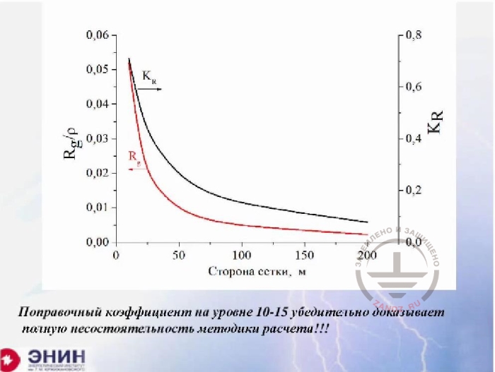
The failure of the calculation method
RU
Сторона сетки, м
Поправочный коэффициент на уровне 10-15…
EN
Mesh size, m
Сorrection coefficient at the level 10 to 15 convincingly proves that the calculation method is totally inconsistent
Now there's a question. Some reference books provide the following calculation of grounding resistance for a mesh. The number of elements of the mesh, i.e. elements in the bus between two nodes, is calculated. There can be several hundred of such elements. The grounding resistance of one element is calculated, and then the value is divided by the number of elements to receive some very small value. Then this value is finalized using the utilization rate. I just want to show you what happens with that utilization rate. I have a square mesh here. The square mesh length (again, the cursor pointer disappeared on my screen. Nadezhda, help me please).
- Give me a second. Thank you.
- Let's see what happens. I'm taking the square mesh and changing its length to see what is the utilization rate value, if we are going to use the rate. This utilization rate is on the left. Look at the result for the mesh size of a hundred meters. And this is quite a typical size for the mesh. This utilization rate goes to the level of one hundredth or less. Can you imagine that? You make a calculation and then you correct it up to 100 times of the resulting value. This is absurd. You should use the Laurent formula, of course, but doing mesh calculations using the utilization rate is a complete disgrace, in my opinion.
Calculation in the two-layer soil
RU
Расчет в двухслойном грунте
Отражение ведется поочередно в двух…
Ряд №1…
Ряд №2
Основной ток…
Реально достаточную точность….
!!!Обойтись без компьютера нереально!!!
EN
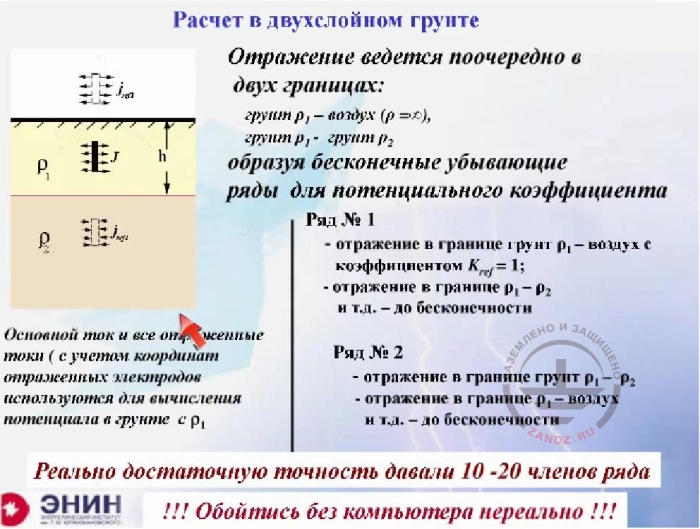
Calculation in the two-layer soil
The reflection occurs alternately in two borders:
ground ρ1-air (p=D),
ground ρ1-ground ρ2
making incessantly decreasing rows for the potential coefficient
Row №1
- reflection in the border ground ρ1 – air with coefficient Kref=1;
- reflection in the border ground ρ1- ρ2 etc. to infinity
Row №2
- reflection in the border ground ρ1- ρ2
- reflection in the border ground ρ1 – air etc. to infinity
The main current and all the reflected currents (with consideration of reflected electrode coordinates) are used to calculate the potential in ground c ρ1
A sufficient accuracy was provided by 10 to 20 members of the row
!!! It is not realistic to calculate this without software!!!
And, finally, there’s the last thing. It is very often said that it is better to make calculations for dual-layer and multi-layer soils. Without a doubt, it is better to make calculations for multi-layer soils. The simplest case is that you have a certain value of soil resistivity p1 and the next ground with resistivity p2. And you are, for example, in the area with the soil resistance p1, and the current certainly gets into the soil with resistance p2. Can we calculate such a case? Of course, we can, if we use mirror reflections methods for such calculations. First, from here to there, then from here to there, and so on. You get the same set of equations with potential coefficients, but each of these potential coefficients is expressed in the form of an infinite series. For real-life calculations, it is about 10 - 20 rows of this series is enough. But when you take into account that you have a number of potential coefficients, and each potential coefficient should be calculated in a row which 20, 30, 40 members, then such calculations are easily made with modern software, but not manually in any way. It is absurd to expect that such a calculation can be done manually or with the help of some kind of correction factors. Now, in conclusion, I want to tell you another thing. One of the software programs to make these calculations is the one we've given to ZANDZ project. And I hope that ZANDZ project will publish this program in a usable format. Calculation using the software is easy but useful because by taking into account different options you can, first of all, understand what ground electrode systems are effective and what are not, and thus save the electrodes. After all, if the electrodes are fixed poorly, i.e. if the utilization rate of the ground electrode system is low, this means that you literally bury your iron in the ground. Lastly, all of these software products without exception are suitable to calculate the step voltage and touch voltages. I've said nothing, quite consciously, about how to calculate the step and touch voltages, but it is important to calculate them for the following reason. All accidents involving people and animals are related to the impact of the step and touch voltages in 99% cases.
Questions and answers session
- I am ready to answer your questions, although I understand that it is certainly difficult to ask questions about a lecture which mainly consist of calculation formulas. I hope you have questions.
- Yes. Good afternoon everybody. We’ve got one question already. How does ground electrode material influence the calculations?
- Thank you very much. Actually, it's a great question, you know. This is a great question and I am sorry I did not mention this. Here's the matter. Soil resistivity is a value somewhere at the level of 100 Ohm * m. For example, if we have black soil, then it will be 70 Ohm * m, and if it is wet loam, then 200 Ohm * m. That is the resistivity of a good ground is approximately 100 Ohm * m. The resistivity of the metal, even the most common one, like black steel, is 10-7 Ohm * m. So whatever metal you use, it is a billion times better as a conductor than the soil. It doesn't really matter what metal you'll take for the calculation. When calculating the grounding resistance, any metal can be considered a superconductor without fearing to make a major error. For this reason, you can consider that the potential at any point of your ground electrode system in the steady state has absolutely equal values. Therefore, the grounding resistance calculation can be carried out with an assumption that all the ground electrodes have a zero resistivity to the direct current. It should have said that from the very beginning. It’s my fault. Is there anything else?
- Yes. Our colleagues are becoming more and more active and sending lots of questions. How to calculate the angular profile?
- How to carry out the calculation of the angular profile?
- Yes.
- You know what? The situation is like this with the angular profile. You need to know what equivalent radius should be put in the calculation formula if you mean an angular conductor. So you are using an angle. Most handbooks say that the radius is selected as a half of the angle size. We do not niggle here, do we? The fact is that the radius goes under the logarithm, and the value of this radius will make a little change if you measure it with 10% accuracy because the value under the logarithm is the electrode length divided by the radius. The radius changes the value itself, but not its logarithm. So in real-life calculations, you have to consider the following. Take the length of the angle and a radius equal to half the length. If you want to be even more precise, then do the following. Calculate the area of this angle and take the equivalent radius for this area. But you'll get almost the same result.
- OK. There's a hip of questions, so let us answer in brief if possible. What is the optimal distance between the electrodes? That is, divisible by the length? What is the ratio?
- Here's my advice. I would advise you the following. Never provide a distance between the electrodes less than their length. In this case, your electrode will certainly serve as a shield, but as I've shown in the calculation, at a distance comparable to their length the currents in them become almost identical. This means that the electrodes have almost no effect on each other. This is a rule: the distance between the electrodes is more or less equal to their length. And the rule is good enough to make ground loops in real life.
- OK. - What handbooks do you recommend for the calculation of grounding devices?
- What?
- What handbooks or reference books do you recommend for the calculation of grounding devices?
- The situation with reference books is very bad. You know, right now we are preparing an article for ZANDZ.com website. There will be everything I've told you today, but only with more details in the article. Because if you take books related to the calculation of ground resistance... These are books on electrical safety, generally. You will only find calculations that use the utilization rate. And these are bad calculations, and you clearly don't want to use them as guidance. Here is the thing. I've said that the calculation of grounding resistance and capacitance are almost the same. Capacity is the value inversely proportional to the grounding resistance, or one divided by the grounding resistance. So they are the same. And there is a very good reference book for the calculation of capacitance written Yossel and... I cannot remember the second author. But if go to the Internet, then you will certainly find the book. You can read a theoretical part before proceeding with the formulas, which, in my opinion, is very useful in any case. When I wanted to specialize in grounding resistance, I used this book many times.
- There's a question. - Can I use the equivalent soil resistivity for the calculation of grounding resistance in the multilayer soil?
- Yes, of course. Of course, you can! Moreover, everybody does so. You know, the matter is this. The multilayer soil is, in general, a hoax to some extent. The method of grounding resistance evaluation of these layers is so imperfect that I would use the calculation by the equivalent resistance only, and nothing else. Because everything else that uses variations of the vertical electric probing method that determines it all, is effectively a kind of niggling.
- What are the specific features of grounding device calculation for the permafrost soil?
- Is there any sense to use large metal plates for the grounding?
- Look. I will answer this way. I do not see any reason to use large metal plates. Unless you get a large metal plate for free, of course. I will explain what I mean by "for free". You are constructing a high-rise building. A foundation slab is laid for the high-rise building. This foundation plate is made of normalized reinforced concrete. The rebars of the concrete are in fact an absolute equivalent to a solid slab. So in this case — yes, this slab should be used as a plate-like ground electrode system. But if you want to put a real metal plate, then you will be wasting 95% of the metal. You can calculate it this way. Take the mesh, begin reducing the size of its cells, and leave the overall dimensions of the mesh unchanged. You will see that after you've left a certain distance, the size of mesh cells will almost stop influencing the grounding resistance. This means that you lay metal in vain. This is just not worth it. But if you get the plate as a foundation slab anyway, then that’s great.
- There also was a question about the calculation method for deep ground electrodes.
- Deep ground electrode system. Look. I'll get back to the slide. Here's the slide.
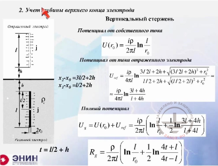
Accounting for the depth of the electrode upper end
RU
2. Учет глубины верхнего конца электрода
Вертикальный стержень
Потенциал от собственного тока
Потенциал от тока отраженного электрода
Полный потенциал
EN
2. Accounting for the depth of the electrode upper end
Vertical rod
Own current potential
Reflected electrode current potential
Total potential
Look. In fact, it says that no restrictions on the value h exist at all. You can calculate any deep ground rod using these ratios. There are no restrictions here. The only thing is that you need to use the soil resistivity value as the equivalent resistance for the place where the deep ground rod is installed. All the rest will do.
-There was another question. Do you need to take the depth of soil humidity into account?
- Let me explain one thing. There is no alternative to that in the theory we are reviewing, as we operate with the values of the grounding resistivity. Of course, it depends on the humidity. And you can consider this relationship by entering different values of grounding resistance and equivalent grounding resistance for different layer depths. But the value of soil humidity certainly cannot be used in this calculation method based on the theory of the DC current electric field. It is used only in the value of soil resistivity. The humidity is included in that p value.
- OK. There was another question. Metal piles, pipes, and viscous cement sealing mixture are used at the facility. Can I ignore this surrounding material and calculate the ground electrode system as if it was buried in the soil?
- Yes, I believe you can. I believe that you can calculate it like this because I cannot imagine one thing. It is unlikely that this reinforcing mixture will take up more than one or two meters. It doesn't work that way. And if so, then moisture will enter this mixture from the surrounding soil. And if you know the resistivity of the soil, then we can assume with a clear conscience that you have no viscous cement mixture at all, and there is only the soil in this place. I am sure this is correct.
- OK. There was also a question about the difference between the potentials of ground electrode systems not connected with each other. How to determine it? Between the two grounding devices not connected to each other.
- Thanks once again for the wonderful question. You know, this is a really good question. This is done as follows. A single ground electrode system is calculated. One ground electrode system is the system the current enters into, and the second system that has no current. That is, there is current in its electrodes, but the sum of the currents in them is specified as zero. Look. The current does not enter this adjacent ground electrode system. And you write a system of equations. You further assume that the sum of the currents in the ground electrode system equals not to zero, but to the current that enters there. And currents are present in the adjacent ground electrode system but the sum of these to currents also equals to zero because no current comes there. And if you solve such a system of equations, then you will find out two things. You will find the potential of ground electrode system that transfers the current into the soil and the potential of another ground electrode system that does not transfer any current into the soil, i.e. acts as a passive element. We ourselves have a special program that allows solving that set of equations easily. If you really need it for some serious purpose, I recommend you write down the phone number I'm giving you right now and we will help you in that specific question because it is very narrowly focused. The phone number is: 495-Moscow code- 770-31-59. Once again: 770-31-59. This is my personal phone number, so please do not call me on Fridays. I almost never stay in the office on Fridays. We have the software and we have addressed this issue specifically. I can tell you one thing just to make you feel the essence of the problem. If these ground electrode systems are within 20 meters from each other and their areas are roughly comparable, then a double-digit percentage of current you dissipate in the soil can come there. That is, the effect will be noticeable. Any more questions?
- Yes. Here's a question. The facility is located on a rock. The grounding is two plates thrown into the water. How do you calculate that?
- This issue has two answers. The first answer is DC grounding resistance. If we talk about the DC grounding resistance, then the resistance of the long wire you've immersed in the water doesn't really matter. You are just calculating the grounding resistance of the plate. By the way, it is included in all reference books because there is the capacitance grounding resistance there. And if there is a calculation of capacitance resistance, then the plate is calculated the same way. Therefore, the value of plate grounding resistance is included in all reference books. And then you take the resistivity of water. The resistivity of the water depends on the water itself. If the water, for example, is from Moscow, it is approximately 20 Ohm * m, if water is from St. Petersburg, then it is softer and the resistivity will be approximately 40 Ohm * m. And if it's the Black Sea water, in Crimea for example, it will be about 2 Ohm * m. You just have to learn the grounding resistance of water and calculate. But there is another point here. If the ground electrode system is used to divert the lightning current, then it is a different case. Then the problem is very serious. The problem is very serious, and that's why. For example, you have a high rock, about 100 m high. In this case, the wave of current reaches the ground electrode system at a speed of 300 meters per microsecond. This means that it will cover a distance of 100 meters within approximately 1/3 s. And during this 1/3 ms, the lightning current grounding resistance will be equal to the surge resistance of the wire, which hangs in the air. It will be about 300 Ohm, or at least 200 Ohm. When the wave reaches the water, is reflected back and runs another 1/3 ms, only then the lightning will feel that the grounding resistance has been reduced to the value provided by the water. This will happen with a delay of about 2 / 3mkrsek, during which the lightning current can rise to a highest possible value. Reaching the maximum value is quite possible. This means that your ground electrode system this will work with a lag. This is a very unpleasant thing. This is dangerous both from the safety standpoint and the standpoint of equipment protection. Therefore, this problem has two answers.
- A colleague of mine has heard of a chemical protection method. You dig a pit and fill it with a chemical composition, which then hardens. How effective is it?
- I've also heard about this chemical method. At the past conference on lightning protection, one of the Russian companies has offered the same thing as you mentioned, only a bit simpler. They drill a well. And this well is pressure-filled with a mass consisting of graphite and binding compounds. As a result, a block several meters in size is formed in the soil, which is used as a grounding loop. They tout this stuff and state that the block is long-lived and can be used the same way as a metal ground electrode system for at least 10 years. This thing just exists, and you can't ignore it. But there is another point here. And the thing is this. You dig this reservoir and pour some liquid mixture there. And the liquid mixture has a very low grounding resistance. You really get it, but the diffusion of liquid components will occur quickly enough in the soil. I suspect that by the next thunderstorm season only a tiny share of this liquid mixture will remain in the soil. My answer is vague, and this is because I do not know what specific device you're talking about.
- Another question follows your answer about the grounding in water. Will the situation be the same if you have a lightning rod on a high-rise building?
- The situation with this building will be absolutely the same. But there is one different thing, which is serious enough. I mean the following. The current goes through not just one down conductor in the building, but through a very large number of metal reinforcement bars. So before the wave goes through, the surge impedance will not be 200 Ohms but substantially lower. It will be a double-digit value. This is the surge impedance of the building. There's nothing to worry about in this case. And this is evidenced by the practical experience of high-rise buildings operated in both Russia and America, and wherever you want. No serious problems were detected.
- I tried not to miss your questions. So there's the last one. How to carry out a grounding system at an open-cut mine, where the gravel layer is 100 meters deep?
- You know what? There are two options.
So I know another option. A residential area was under construction at the Samara region, and the developers discovered that the ground plot was just a solid rock. And they needed to make a grounding system for a substation and an electrical safety grounding system. So they put a dredger in the Volga River. And then, the dredger shaped a pillow on the rock four meters thick. Again, this is very expensive. And I do not know what can be done cheaper.
- Are there any standards that regulate the size of crushed stone or gravel for backfilling?
- I do not know such standards.
- And there's another question. Can you take seasonal ratios into account?
- Yes, you can, and you should. You can do it and you have to take them into account in any case. And the seasonal ratios are something like this. Let me explain that. The less is the ground electrode system in size, the more important is the seasonal ratio. We've already talked about it during our previous webinar. During the event, I tried to show what would happen to seasonal ratios in the case when you ground electrode system had a small area and otherwise. For large area ground electrode systems, seasonal ratios are about ten or at best twenty percent. I mean a grounding loop 200 * 200 m in size, for example. This is a grounding loop for a substation or a manufacturing plant. But if the ground electrode system consists of just two ground rods driven into the ground, then the seasonal ratios will change your grounding resistance several folds. The company that hosts our webinar has made such measurements by burying a bus 3 meters long in a Russian region. The company monitored the state of the bus for a year. During the year, there were about two seasonal changes here, in a Moscow suburb. ZANDZ.com project has done the project but not yet published its results.
Thank you very much for your attention. I would like to hear all your comments and criticism. Please be sincere, OK? If you feel something’s wrong, just tell me. And one more thing. We have an idea to focus on the lightning protection of specific equipment during our next webinars. How do you like this idea? Do you appreciate it or not? Thank you in advance for expressing your opinion on this subject. Thanks again for your attention.
Do you have any questions left? Send them to our technicians and you will receive detailed and reasoned answers.
<< Previous Page
Slides 10 to 18
Related Articles:
