From the series of articles "Grounding in lightning protection - answers to frequently asked questions in the design".
It is difficult to give a reasonable answer to this question, and I don't know a specialist who can do that. In the beginning of the article it was mentioned, that the change in grounding resistance of a lightning rod in any reasonable limits even to 2 orders of magnitude practically has effect on the efficiency of lightning attraction. Hence, it is necessary to focus on some other criterion, associated, for example, with electrical safety or acceptable level of surges in the electrical circuits of the object. An effort to shape the regulatory requirements on this basis is not meaningless, but it is bound to be related to the mass of unsolved problems. The main one among them - the maximum permissible level of touch and step voltage for humans and animals in a pulse mode. The existing regulation ends here with the voltage exposure time of 0.01 seconds, which is about 2 orders of magnitude greater than in storm conditions. Lightning protection specialist is not very well familiar with physiology and can not offer a reasonable method of recalculation of dangerous voltage levels for humans in another so different time range. Unfortunately, an effort to do that on the condition of equal energy deposition (then instead of permissible 600 W it would turn into to 6 kW) is not scientifically justified.
It is even more problematic to start with an acceptable level of storm surge. Firstly, they are not always in a direct proportion to grounding resistance, and secondly, electrical circuits of different nominal voltage differently react to surges. Besides, these circuits may have protective equipment and there is no single solution to the question of where to invest material resources - into reduction of grounding resistance or into means of limiting occurring overvoltage.
Everything mentioned above leaves the designer one-on-one with the problem. There is not a single word about grounfing resistance of lightning rods In the national standards for lightning protection IS-153-34.21.122-2003. The guide on lightning protection AD 34.21.122-87 only mentiones type design of lightning grounding devices, and their grounding resistance is disregarded. It is useful to understand at least this in order to realize methodological approaches of the standard compilers and assess the appropriateness of the recommended.
For a detached lightning rod,AD 34.21.122-87 indicates 3 constructions of ground electrode systems, subject to a specific calculation:
- towe body of at least 5 m long and not less than 0.25 m in diameter,
- two vertical rod with the length of at least 3 m, connected by a 5-meters-tape to a depth of at least 0.5 m (diameter 10 - 20 mm),
- three vertical rods of the same dimensions and the same distance between them.
A computer calculation in soils with different resistivity gives the following design ratio for these structures respectively
RW = 0,14ρ
RW = 0,13ρ
RW = 0,10ρ
Ohm
When the lightning rods are installed on the roof of a building, the foundation of which is unsuitable for use as a ground electrode system, the grounding contour 16x16 meters on the outer perimeter in AD 34.21.122-87 is considered sufficient for soils with grounding resistivity of ρ ≤ 500 Ohm * m, and the contour of 30x30 m - up to 1,000 Ohm * m. The grounding resistance of these contours are respectively equal to R3 = 0,035ρand R3 = 0,02ρ Ohms.
It can hardly be called regulation, as in different regions of Russia soil resistivity may well change within 2 orders of magnitude (from 50 to 5000 ohm m, sometimes even higher), and the grounding resistance of separate lightning rods with a standard ground electrode system - approximately from 5 Ohms to 700 ohms. Both of them are norms? I would like to know from what position! The situation with buidlings with lightning rods on the roof is not much better. And nothing is mentioned about the resistivity of over 1000 ohm m in AD 34.21.122-87, although such soils are not uncommon in Russia.
I don't know what can be done for separate lightning rods. Usually, performance of lightning protection with lightning rods or mesh on the roof bases on EIC requirement of uniting all grounding devices in a single process contour. Its grounding resistance is probably not higher than 10 Ohms. It is definitely enough for a reliable operation of the lightning rods. But protection of step and touch voltage is a different thing. Here the situation is serious even when the location of an object in an area with very high conductivity of the ground. To illustrate the problem, let's consider a tyfigal residential building 60 x12 m, the foundation of which is used as a grounding device (fig. 32). The foundation supports are recessed into the ground with the resistivity ρ = 150 Ohm m to 5 m. Computer calculation for this foundation gives grounding resistance R3 = 1.9 Ohm, which fully satisfies the requirements of not only grounding resistance of lightning rods, but also of technological grounding of electric network 380/220 V.
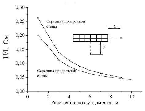
Figure 32
Середина поперечной стены – middle of transverse wall
Середина продольной стены- middle of longitudinal wall
Расстояние до фундамента, м – Distance to the foundation, m
Ом - Ohm
Step voltage distribution pattern is shown in fig. 32 in relation of the longitudinal and transverse walls of the building. The nearest point to the walls of the building determines touch voltage. At the lightning current 100 kA (rated current for lightning protection level III according to IS-153-34.21.122-2003) in the mentioned example is close to 25 kV at the transverse wall of the building and 20 kV at the longitudinal. Both figures are incomparably higher than the value of 600 V, which is a standardized value on electrical safety reasons. The value of 6 kV obtained for the effects of lightning by a formal recalculation in this article, also exceeds in 3 - 4 times. Even at the distance of 10 m from the walls, step voltage still can not be considered safe for human and animals. Unfortunately, there are quite compelling and sad confirmations of that in practice.
In case if the task is really to provide safe lightning current spreading in crowded places, the project of the grounding device should be designed specifically. In this respect, two different approaches deserve attention. The first of them boils down to to the application of a dielectric moisture resistant layer on the ground, which is capable of withstanding step and touch voltage. The AD 34.21.122-87 mentions asphalt as such. The second way is associated with the search of an optimal design of the ground electrode system. First of all, we can talk about a deep-laid ground electrode system of a special design. A rod electrode intended for this purpose should have an insulating coating that can withstand almost full voltage on the ground electrode. The insulated rod part doesn't take part in current spreading. It is required to put the bare part of the metal rod to the desired depth, from which the current will fall to the ground. In fact, the insulation determines the depth at which the upper actively working end of the ground electrode is located.
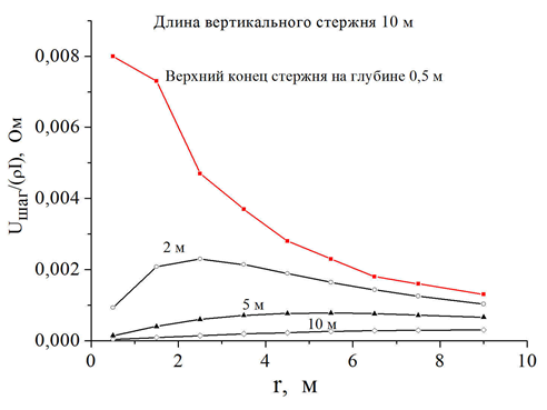
Figure 33
Длина вертикального стержня – vertical rod length 10 m
Верхний конец стержня на глубине 0,5 м – upper end of the rod at the depth of 0,5 m
The design turns out to be quite effective. Calculated data in fig. 33 show that having put the rod electrode on 10 m depth, the step voltage can be reduced in about 25 times. In the result, at the soil resistivity of 100 ohm * m maximum step voltage won't exceed 3 kV even at the lightning current of 100 kA. Of course, the use of a deep-laid ground electrode system can be combined with the use of an insulating coating on the surface of the ground in crowded places.
E. M. Bazelyan, DEA, professor
Energy Institute named after G.M. Krzyzanowski, Moscow
Read more "What you need to know about non-linear properties of soil".
Useful materials:
- Series of articles about lightning protection for beginners
- Series of webinars about grounding and lightning protection with Professor E. M. Bazelyan
- Elements of external lightning protection
- Consultations on the selection, design and installation of grounding and lightning protection systems
Related Articles:
 Lightning protection of residential and public buildings - answers to frequently asked questions in the design
 Lightning Protection of Large Territories: Parks, Grounds, Plant Territories. Page 1
 Lightning Protection of Large Territories: Parks, Grounds, Plant Territories. Page 2
 Lightning Protection of Large Territories: Parks, Grounds, Plant Territories. Page 3