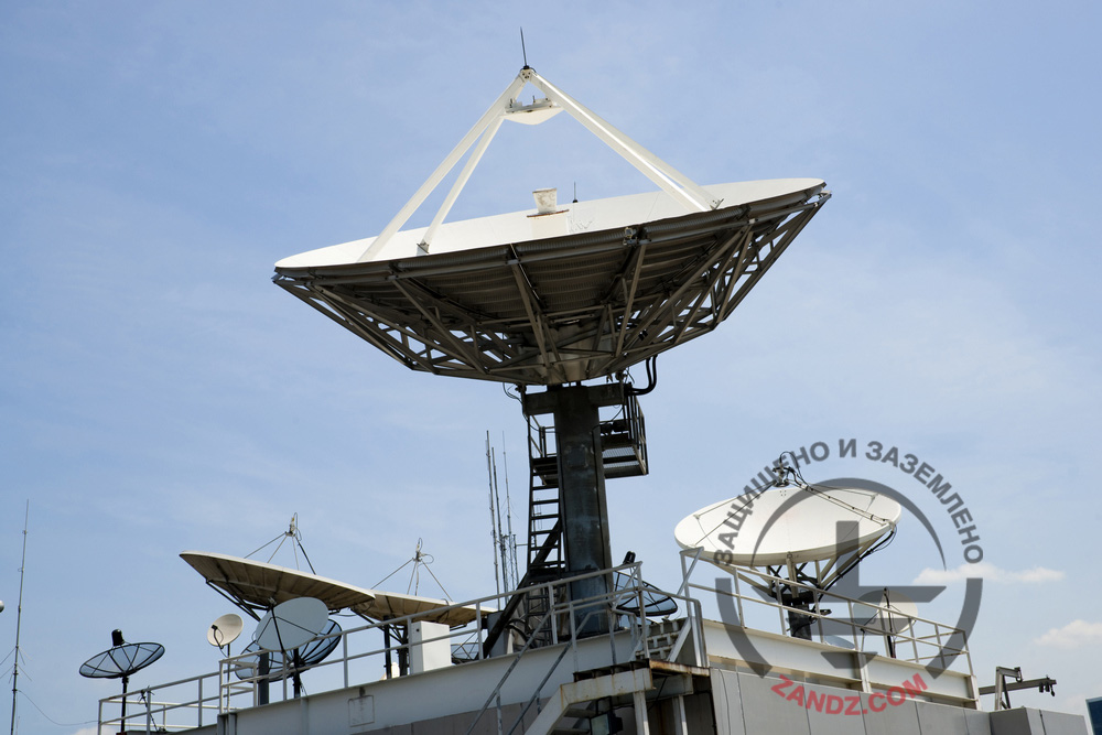
An antenna post is an essential part of a cable TV station. The quality of the subscriber signal depends on the quality of signal transmitted from the antenna post output to the main station input. To provide reliable operation of the equipment, we have to install lightning protection and grounding system at the facility. Such facilities are classified as common according to the regulatory documents and do not imply special lightning protection option. The ZANDZ Technical Center has received a request to calculate the lightning protection for the antenna post of the main cable TV station. Let us continue with more detailed review of our offered solution.
Calculation of the lightning protection for the antenna post of the main cable TV station
Facility: antenna post of the main cable TV station
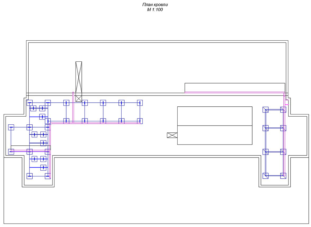
План кровли - Roof plan
Figure 1. Facility plan.
Task: to perform calculations for the lightning protection system for the antenna post of the main cable TV station
Solutions to ensure meeting of the requirements to the lightning protection system for the antenna post of the main cable TV station:
- The lightning protection is made in accordance with Electrical Installations Code (EIC), Rev. 7, SO 153-34.21.122-2003 "Guidelines for the lightning protection of buildings, structures and industrial infrastructure" (hereinafter referred to as SO) and RD 34.21.122-87 "Guidelines for the lightning protection of buildings and structures" (hereinafter referred to as the RD).
- According to RD, the facility is considered as the 3rd category lightning protection facility. The system reliability shall be at least 0.9.
- According to the EIC, Item 1.7.103, total dissipation resistance of grounding electrodes (including natural) of all repeated groundings of the PEN wire of each high-voltage line in any season of the year should not be more than 10 Ohm, respectively, with linear voltages 380 V of a three-phase source or 220 V of a single-phase source.
- Lightning protection of the facility is made using 2 lightning arresters (masts) with a height of 2 m installed on the roof ridge (GL-11521SS) and 6 lightning arresters (masts) with a height of 10 m installed on holders for the walls (ZZ-201-010-3), 2 m for the mount and 8 m for the upper part.
- A copper-plated steel wire (copper coating thickness of 70 μm min.), d8 mm (GL 11149) is used as a down conductor.
- The current collectors are installed using holder GL-11564A on the roof ridge, using holder GL-11747A on the roof pitches, using holder GL-11703A on the vertical surfaces. The accepted pitch of terminals is 0.8-1.0 m.
- The universal terminal GL-11551A is used to connect rolled products along the length and in joints.
- All metal elements located on the roof must be connected to the main conductor cable with the terminals GL-11545. Stairs, railings, are attached using the terminal-clamp GL-11514N.
- Vertical copper-plated steel electrodes with the length of 6 m are used as grounding arrangements. The copper-plated steel strip with a cross-section of 30x4 mm, combining all vertical electrodes is used as a horizontal ground electrode. The distance to the facility foundation is at least 1 m. Strip deepening is 0.5 to 0.7 m.
- According to EIC-7 issue, par.1.7.55 - Grounding devices for protective grounding of electrical installations for buildings and structures and the 2nd and 3rd categories lightning protection of these buildings and structures, as a rule, shall be common.
- If there are concrete-steel constructions, they shall be connected to down conductors/grounding device.
- Connection to the grounding device is carried out using ZZ-005-064 clamps.
Results of the calculation performed using the software developed by the Krzhizhanovsky Energy Institute (OAO ENIN):
density of lightning strikes into the ground is 4 strikes/sq. km per year.
Total number of strikes into the system is 0.20 (once per 5 years).
Total number of blowouts is 0.014 (once per 71 years).
The probability of a blowout into the system's facilities is 0.069.
The system reliability is 0,931.
Ground terminal resistance calculation:
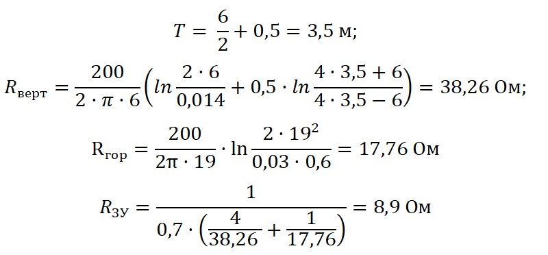
м - M
Верт - Vert
Гор - Hor
ЗУ - GA
Ом - Ohm
The design resistance of the grounding arrangement is 8,9 Ohm.
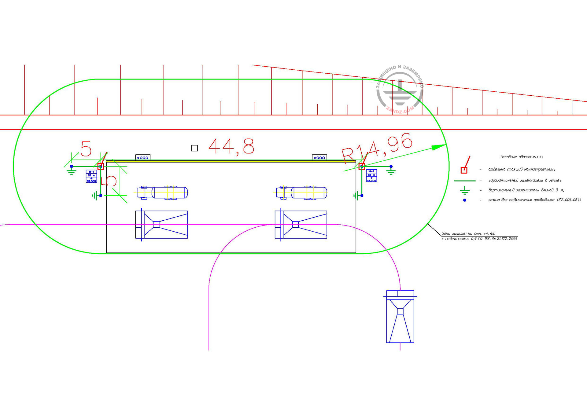
Figure 2 shows hardware layout.
Table 1 includes the list of required hardware and materials.
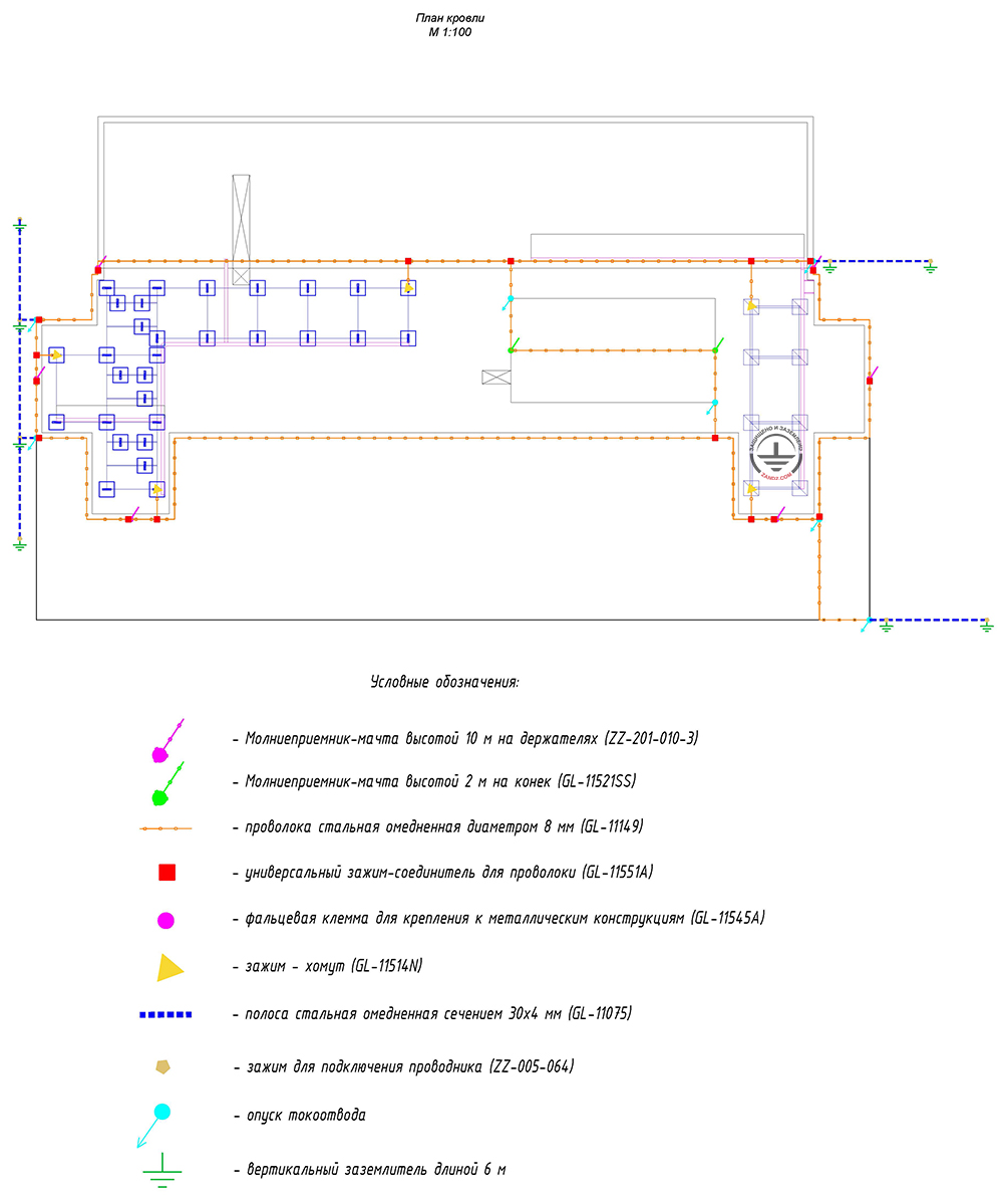
Figure 2. Layout of equipment for the lightning protection for the antenna post of the main cable TV station.
План кровли - Roof plan
Условные обозначения: - Key:
Молниеприемник-мачта высотой 10 м на держателях - 10 m lightning rod with holders
Молниеприемник-мачта высотой 2 м на конек - 2 m lightning rod to the ridge
Проволока стальная омедненная диаметром 8 мм - Steel copper-plated wire, diameter 8 mm
Универсальный зажим-соединитель для проволоки - Multipurpose connecting clamp for wire
Фальцевая клемма для крепления к металлическим конструкциям - Flange terminal for connecting to metal structures
Зажим-хомут - Collar clamp
Полоса стальная омедненная сечением 30х4 мм - Steel copper-plated bar, cross-section 30 x 4 mm
Зажим для подключения проводника - Clamp for conductor connecting
Опуск токоотвода - Downdrop
Вертикальный заземлитель длиной 6 м - 6 m vertical grounding electrode
Table 1. List of material requirements.
Do you have any questions about lightning protection for the antenna post or other facilities? Please, contact the ZANDZ Technical Center!
Related Articles: