We have received a task to calculate the lightning protection for the 100 kV electrical substation with a closed switchgear (CSW). It is technically easier to protect it against lightning than the substation with an open switchgear since it has a smaller footprint, and the entire high-voltage equipment is located in the same building.
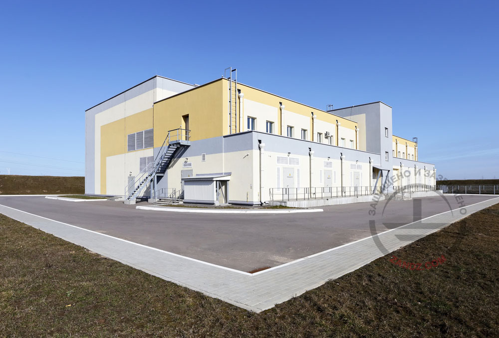
To provide the lightning protection of the substation with the CSW on the roof, it is allowed to make a grid with the cells not exceeding 10 x 10 m, which conforms to the requirements provided in Item 3.3.3. of SO 153-34.21.122-2003 for the Level III protection. Downdrops to grounding devices should be provided every 20 m according to Item 3.2.2.3 of the regulatory document.
Let us consider the lightning protection for the substation in more details.
Task
The lightning protection is installed at the substation.
Solution
Calculations of the substation lightning protection system are made in conformity with the following regulatory documents:
- "Electrical Installations Code" (hereinafter referred to as the EIC), 7th edition.
- "Instructions for the installation of lightning protection of buildings, structures, and industrial communications" SO 153-34.21.122-2003 (hereinafter referred to as SO).
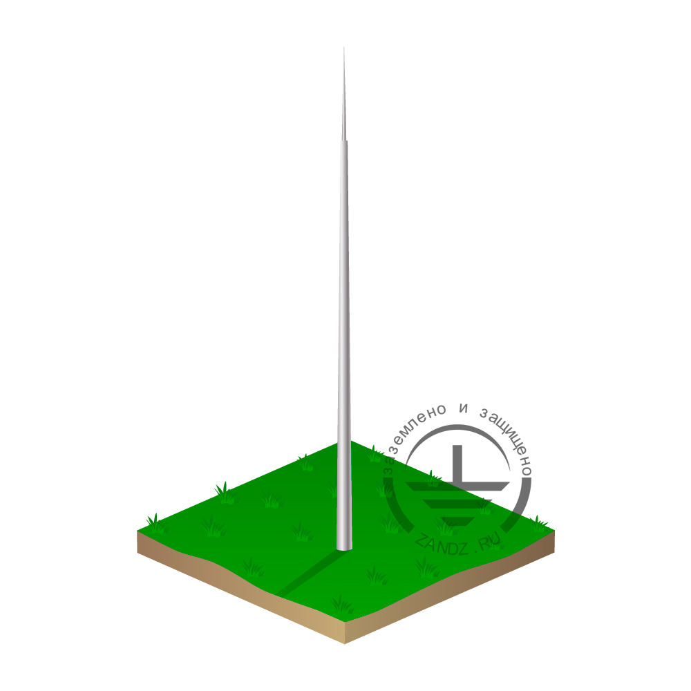
The lightning arresters are used to protect the buildings against lightning strokes. The lightning arrester consists of an interception rod, intercepting a lightning discharge, the main conductor cable, and the ground electrode. All these elements let us divert lightning current into the ground safely, without any damage to the protected facility.
110 kV substation is classified as a special limited hazard facility in terms of lightning protection according to SO.
Description of the substation lightning protection system
A set of arrangements ensuring compliance with the lightning protection requirements is based on the following solutions:
- The facility's lightning protection is made as a lightning grid using a steel zinc-coated wire having diameter 8 mm, which is installed with the step not more than 10 x 10 m. The grid is made such that the current would have at least two different paths to the grounding arrangement. Downdrops to the grounding arrangement are made with the step not less than 20 m along the building perimeter.
- The main conductor cables are mounted (with mounting step 0.6-1 m):
- on a flat roof using clamps ZZ-202-015;
- to the walls using clamp GL-11703A.
- Connection and branching of current collectors are made using clamps GL-11551A.
- All metal elements protruding from the roof (ladders, pipes, shafts, vents) should be attached to the lightning grid using clamps ZZ-005-064.
A set of measures to ensure the necessary requirements for the grounding device of each interception rod is represented by the following solutions:
- The connection of the current collector with the output of the zinc-plated bar from the ground is performed using the clamp ZZ-202-012.
- The 5 x 50 mm zinc-plated steel bar is installed up to the existing grounding arrangement and is connected thereto using clamp ZZ-202-012.
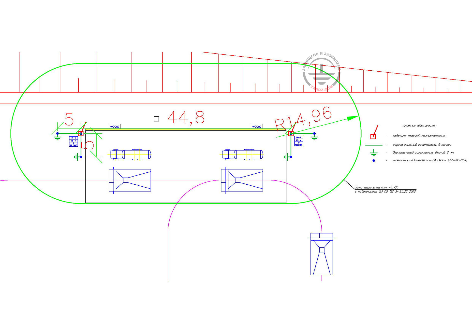
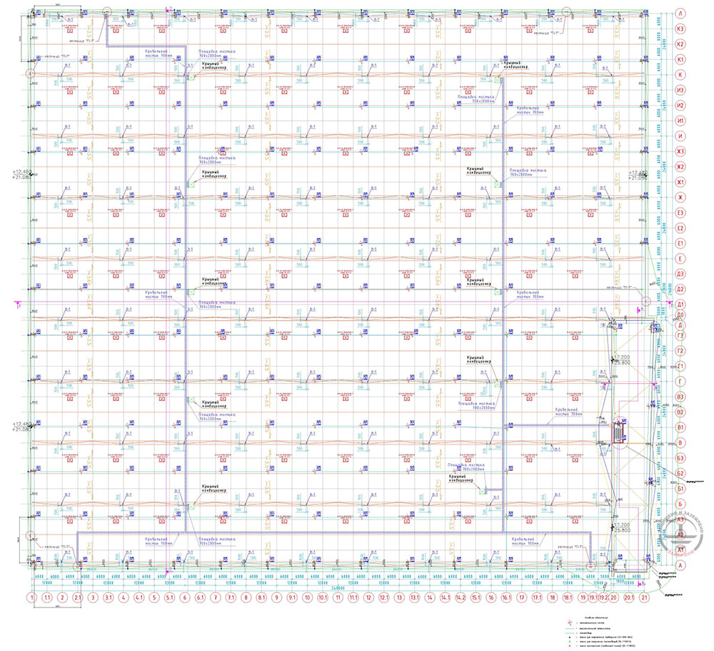
The location of the elements of the lightning protection system and the grounding arrangement is shown in Figure 1.

Figure 1. Layout of lightning protection elements in the substation.
Условные обозначения - Key
План на отм. - Plan at mark
Components of the substation lightning protection system
| № | Part number | Name | Quantity, pcs. |
| Lightning protection system | |||
| 1. | ZZ-502-008-125 | ZANDZ Zinc-plated steel wire (D 8 mm / S 50 mm²; wire bundle 125 m) | 4 |
| 2. | ZZ-202-015 | GALMAR Flat roof terminal for the main conductor cable (D8 mm; plastic, concrete) | 250 |
| 3. | GL-11703A | GALMAR Terminal for fastening the main conductor cable with elevation (15 mm height; galvanized steel with painting) to the facade/wall | 150 |
| 4. | GL-11551A | GALMAR Terminal for main conductors connection (painted galvanized steel) | 35 |
| 5. | ZZ-005-064 | ZANDZ Conductor connection terminal (up to 40 mm) | 20 |
| Grounding arrangement | |||
| 6. | ZZ-202-012 | ZANDZ Clamp for circular wire and bar (D14-20 mm; up to 40 x 6; zinc-plated steel) | 12 |
| 7. | ZZ-502-505-6 | ZANDZ Zinc-plated steel bar (50 x 5 mm; 6 m rod) | 3 |
| 8. | ZZ-007-030 | ZANDZ Waterproofing tape | 2 |
Do you have any questions regarding the calculation of the lightning protection and grounding for a substation? Please, contact the ZANDZ Technical Center!
Related Articles: