The work of the lightning protection designer becomes better due to the buildings introducing unusual constructive solutions. A recent project is interesting in its complicated architecture and mandatory requirement of the customer: to calculate the lightning protection level in the ENIN software only.
The building is intended for the passengers waiting for their flights for a long time. Such facilities do not have any special requirements in the regulatory documents, but lightning protection and grounding must be made. First, architectural and constructive solutions of the building are analyzed. The facility has relatively large dimensions, average height, and many branches. Then, we think of the lightning protection concept and check the protection level using our own service based on the ENIN software suite.
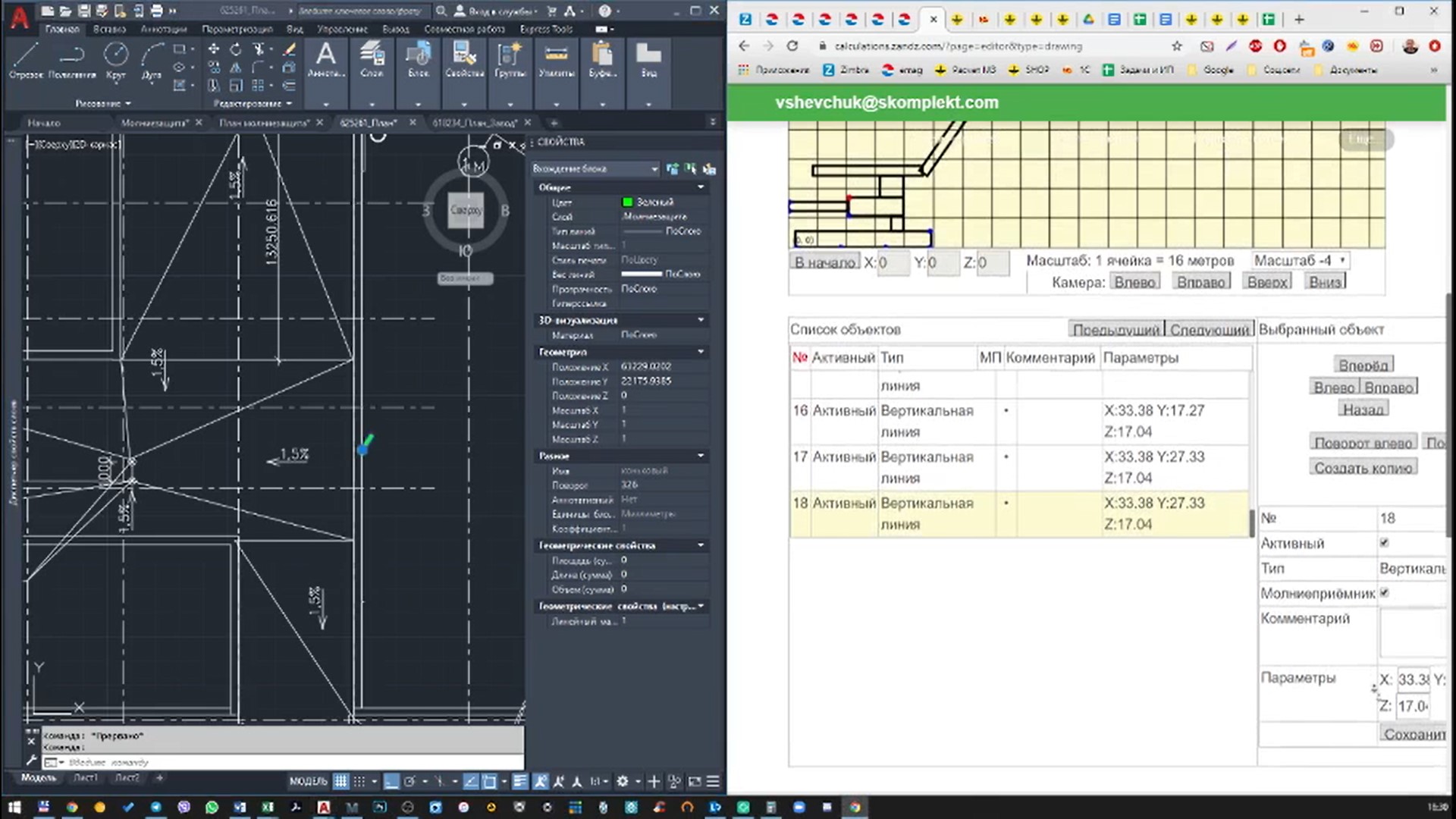
The calculation shows that, initially, the proposed amount of lightning rods is excessive. OK, we can reduce their number and optimize the location. This is shown in the video. The final result of optimization of the lightning arrester part is 90% reliability, which is a good result, i.e. the third category according to RD and SO.
We document solutions in the Lightning Protection and Grounding Diagram, brief Explanatory Note and Specifications for equipment and materials. We attach a Report of Calculation of the Software Protection and Certificate to the Explanatory Note. So, one more building is safe now.
Do you want us to perform calculations for your facility? It is free of charge. Write a request to our e-mail or call us. We are happy to help you.
The details of the public building lightning protection are provided below. They are useful for performing calculations independently, if required.
Calculations of the public building lightning protection.
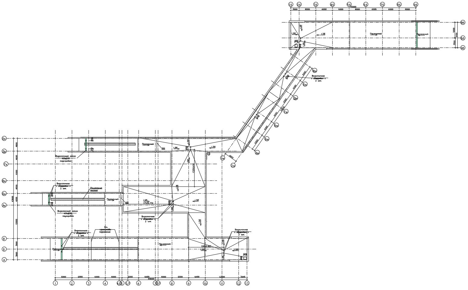
Figure 1. Facility plan
Task: to perform calculations for the lightning protection system.
Solutions to fulfil the requirements for the lightning protection system:
- The lightning protection is made in accordance with Electrical Installations Code (EIC), Rev. 7, SO 153-34.21.122-2003 "Guidelines for the lightning protection of buildings, structures and industrial infrastructure" (hereinafter referred to as SO) and RD 34.21.122-87 "Guidelines for the lightning protection of buildings and structures" (hereinafter referred to as the RD).
- The facility belongs to Class III according to RD. The system reliability shall be at least 0.9.
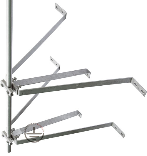
- The facility's lightning protection is made using 11 x 4 , lightning rods ZZ-201-004 located on walls (1 m for securing and 3 m from the top).
- A copper-plated steel wire (copper coating thickness of 70 μm min.), d8 mm (GL 11149) is used as a down conductor.
- Current collectors are installed using clamp GL-11703A on vertical surfaces, and GL-11711 on a flat roof. The accepted pitch of terminals is 0.8-1.0 m.
- All metal elements located on the roof must be connected to the main conductor cable with the terminals GL-11545. Stairs, railings, are attached using the terminal-clamp GL-11514N.
- The universal GL 11551A clamp is used to connect the rolled products over the length and in assemblies.
- The vertical copper-plated steel electrodes with the length of 3 m are used as the grounding devices at the downdrops of the down conductors. The copper-plated steel strip with a cross-section of 30x4 mm, combining all vertical electrodes is used as a horizontal ground electrode. The distance to the facility foundation is at least 1 m. Strip deepening is 0.5 to 0.7 m.
- According to EIC-7 issue, par.1.7.55 - Grounding devices for protective grounding of electrical installations for buildings and structures and the 2nd and 3rd categories lightning protection of these buildings and structures, as a rule, shall be common.
- If there are concrete-steel constructions, they shall be connected to down conductors/grounding device.
- Connection to the grounding device is carried out using ZZ-005-064 clamps.
Results of calculation performed using the software developed by the Krzhizhanovsky Energy Institute (OAO ENIN):
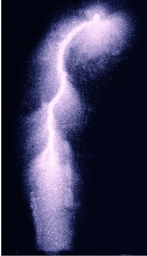
lightning discharge density into the ground is 4 strikes/sq. km per year.
Total number of strikes into the system is 0.13 (once every 8 years).
Total number of blowouts is 0.014 (once per 71 years).
The probability of a blowout into the system's facilities is 0.10.
System reliability is 0,9.
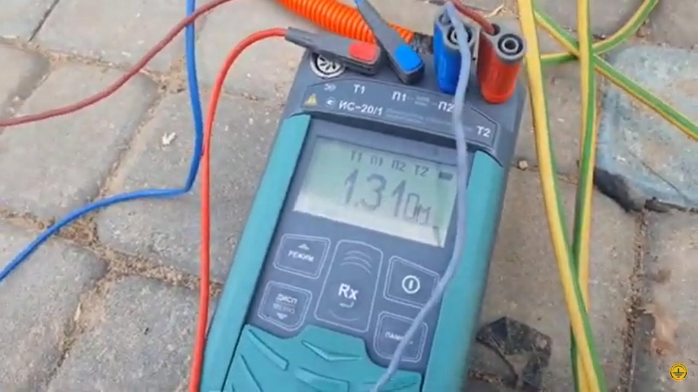
Ground terminal resistance calculation:
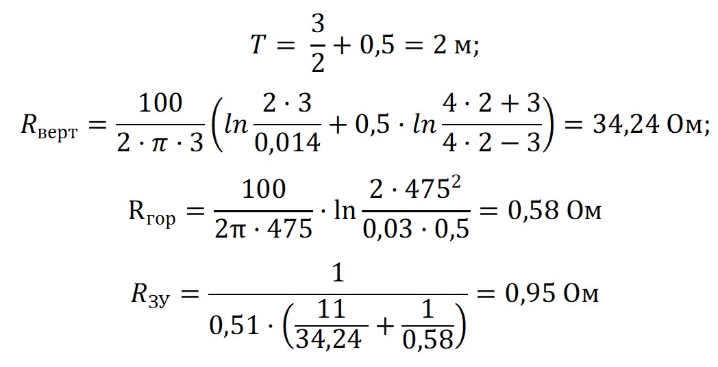
Ом - Ohm
Верт - Vert
Гор - Hor
ЗУ - GA
The design resistance of the grounding arrangement is 0,95 Ohm.
Figure 2 shows hardware layout.
Table 1 includes the list of required hardware and materials.
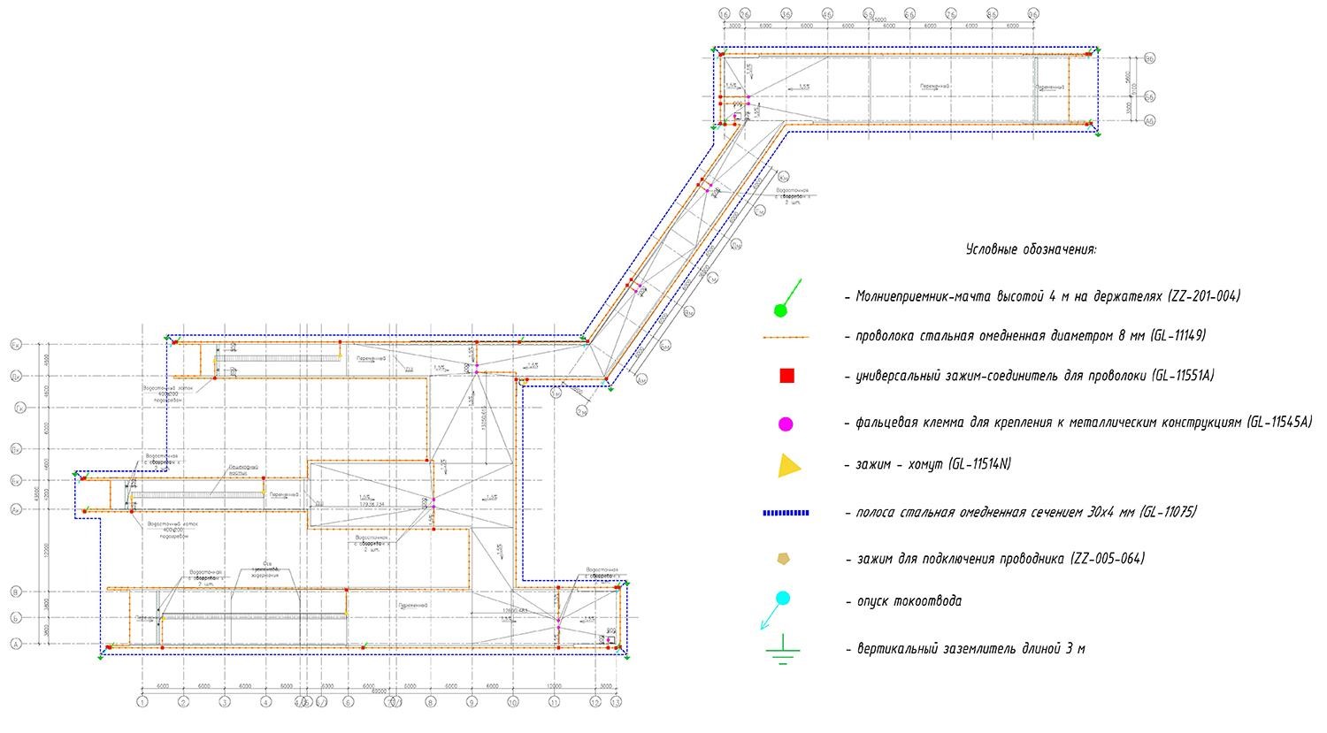
Условные обозначения - Key
Молниеприемник-мачта высотой 4 м на держателе - 4 m lightning rod on a holder
Проволока стальная омедненная диаметром 8 мм - Steel copper-plated wire, diam. 8 mm
Универсальный зажим-соединитель для проволоки - Multipurpose connecting clamp for wire
Фальцевая клемма для крепления к металлическим конструкциям - Flange terminal for connecting to metal structures
Зажим-хомут - Clamp
Полоса стальная омедненная сечением 30х4 мм - Steel copper-plated bar with cross-section 30 x 4 mm
Зажим для подключения проводника - Clamp for connecting wire
Опуск токоотвода - Downdrop
Вертикальный заземлитель 3 м - 3 m vertical grounding electrode
Figure 2. Layout of hardware for the lightning protection of a public building
Table 1. List of material requirements.
Watch video for the calculation process:
Do you have any questions about lightning protection of the concourse or other facilities? Please, contact the ZANDZ Technical Center!
Related Articles: