The sixth webinar of "Surge protection" series
Webinar text. Page 5
Fast navigation by slides:
1. Limiters by RST
2. About Miroslav Zelenkevich
3. Plan of presentation
4. Sources of damages
5. Types of damages - D1: shocking living beings
6. Types of damages - D2: physical damage
7. Types of damages - D3: damage to internal systems
8. Lightning risk analysis as per IEC 62305
9. Lightning protection levels
10. Discharge protection means
11. Zonal protection concept
12. Introduction into the surge protection
13. Zonal protection concept principles
14. Normalized current pulses
15. Production of RST limiters
16. RST Limiters production stages
17. Surge limiters testing
18. Execution of documentation
19. Type tests as per IEC 61643-21
20. Test scope as per IEC 61643-21
21. Voltage limiter requirements
22. Categories of stability
23. Pulse tests in the laboratory RST
24. High-energy impact test
25. Climatic tests
26. Test oscillograms
27. Determination of limiter nominal parameters
28. Substantiation of tests
29. Example of parameters given by manufacturers
30. Parameters of SPD from other manufacturers
31. Example of factory test parameters
32. Example of gas limiter
33. Results before and after testing
34. Complete scheme resistance test
35. Temperature resistance test results
36. Correct parameters of limiters as per IEC 61643-21
37. Technical data of limiters
38. Surge limiters by RST
39. RST Guard series limiters
40. RST Guard surge protection device
41. RST Guard HF SPD
42. RST Guard S SPD
43. RST Guard RS485 SPD
44. RST Guard GDT and RST Guard Audio SPDs
45. RST SAP SPD
46. Nominal voltage of SPD
47. RST AL series limiters
48. Table with voltage parameters
49. RST AL HDC SPD
50. RST AL RS SPD
51. RST AL HF SPD
52. RST NET and RST CCTV BNC-1 SPDs
53. RST NET PoE SPD
54. RST CCTV BNC-1 SPD
55. CCTV SPD
56. ZOP overvoltage protection circuits
57. RST TV camera protection circuit
58. Circuits identification code
59. Damage alarm
60. RST AL TMP alarm module
61. Robotic arm protection circuit
62. Central unit protection circuit
Page 5:
63. Control systems protection circuit
64. Individual protection of hardware
65. Protection at LPZ zones boundaries
66. Protection of control cabinets
67. Telecommunication systems protection circuit
68. Railway automatics systems protection circuit
69. Line power supply circuits
70. Numerical coded circuit blocking
71. Buzzer circuit blocking
72. RST surge limiters for signals and interlocking system
73. Additional funding from European Union
74. IsoPro B TN-C
75. Elementary base for signals and interlocking system
76. Elementary base for signals and interlocking system (continued)
77. Table of technical parameters
78. SPD selection parameters
79. Thank you for attention
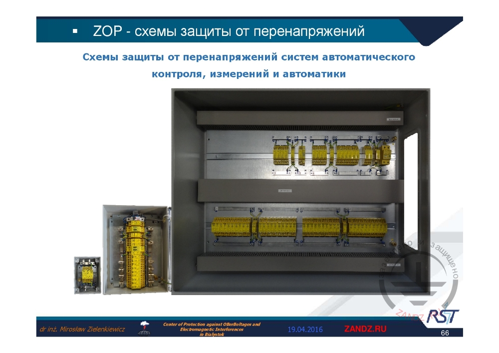
Automatic control systems protection circuit
| Схемы защиты от перенапряжений систем автоматического контроля, измерений и автоматики | Instrumentation and controls automatics overvoltage protection circuits |
— Example of one of the last circuits for the automatics instrumentation and controls, whereas variability of these circuits is so high that we cannot even name it, but assign just a number. It is clear about the variability, because the number of automatics systems configurations for that location is enormous. This cabinet is mounted to the wall of that object, therefore various hardware automatics systems are laid through it. So, we cannot select the elements, just based on the technical data of one automatics system. Generally, we install protection for various hardware, that is installed in that room.
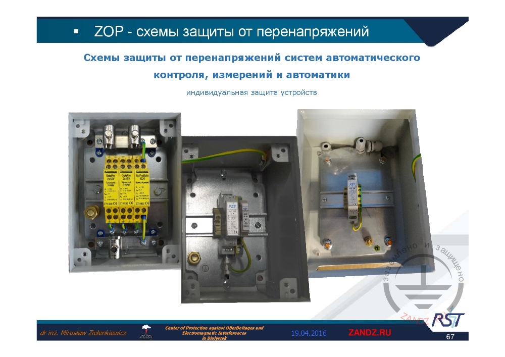
Individual protection of hardware
| Индивидуальная защита устройств | Individual protection of hardware |
— Individual protection of hardware is selected for this specific system, this is why there is a low number of these elements. One, two, three elements, it is locally inside the objects. There is one at the boundary of zones, two inside it.
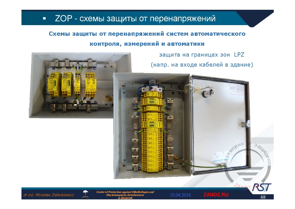
Protection at LPZ zone boundaries
| Защита на границах зон LPZ (напр. на входе кабелей в здание) | Protection at the boundaries of LPS (e.g. at the cabling penetration location into the building) |
— It is at the cabling penetration location into the building, for example, automatics circuit cabling.
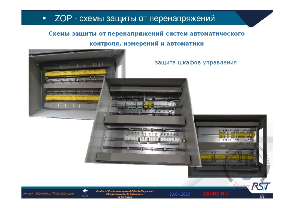
Protection of control cabinets
| Защита шкафов управления | Control cabinets protection |
— We need to discuss the foregoing in details in the next workshop.
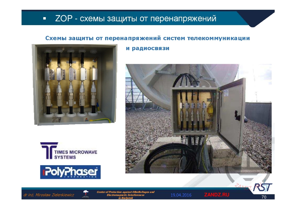
Telecommunication systems protection circuit
| Схемы защиты от перенапряжений систем телекоммуникации и радиосвязи | Telecommunication and radio communication systems overvoltage protection circuits |
— Here we can see the CCTV system protection, one of which is operated in Poland, now there are many of such. On the building roof this circuit protects the camera hardware and what is inside the camera. The second box like this is located at the cabling penetration location into the object. Now, for example, a company, which collaborates with us, now is implementing the project of the Warsaw 180-meter skyscraper protection. The cable length from the room roofing there is 120 meters.
Railway automatics systems protection circuit
| Схемы защиты железнодорожных систем автоматики | Railway automatics systems protection circuits |
— Now I'll show briefly our achievements, because it is the day, when we could display it and demonstrate the cooperation opportunities. There is the Earthing and Lightning Protection on ZANDZ.com powered by a good Russian company. These guys are working in their wide horizons, so we need to have a visit and to watch the protection variant offed by them, as well as the system on-site. There were two cases, when we resolved the lightning current pulses through the railway conductor. In Ukraine, where we just selected the protection upon analyzing the power supply systems and signal systems in cabinets near to railways.
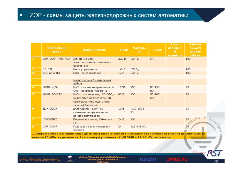
Line power supply circuits
| Обозначение линии | Line ID |
| Линии питания | Power supply line |
| U-ном | U-com |
| Частота/ Dc | Frequency / Dc |
| R жил кабеля + R устройств | R of cable strands + R of hardware |
| Рабочая ёмкость кабеля нФ/км | Operational capacitance of cable nF/km |
| ОПХ-ООХ, РПХ-РОХ | OPH-OOH, RPH-ROH |
| 1П, 2П | 1P, 2P |
| Сигнал А (Б) | Signal A (B) |
| Н-ОН, К-OK | N-ON, K-OK |
| И-ОИ, ЗС-ОЗС | I-OI, ZS-OZS |
| ДСН-ОДСН | DSN-ODSN |
| ПГС-ОПГС | PGS-OPGS |
| СМР-ОСМР | SMR-OSMR |
| Линейные цепи электропитания основные и резервные | Linear power supply lines, main and standby |
| Цепи управления | Control lines |
| Питание светофоров | Traffic light lines |
| Магистральный сигнальный кабель | Railway signal cable |
| Н-ОН - смена направления, К-ОК - контроль перегона | N-ON – direction circuit, K-OK: - control of railway section |
| И-ОИ: извещение, ЗС-ОЗС включение на предвходном светофоре мигающего огня (жёлтый/зелёный) | I-OI: - warning, ZS-OZS: - turning on flash light of pre-entrance signal (yellow/green) |
| ДСН-ОДСН: - двойное снижение напряжение на лампах светофоров | DSN-ODSN: - double voltage reduction of traffic light lamps |
| Перегонная связь, обходная ПГС | Railway section communication, Bypass communication |
| Голосовая связь тональной частоты | Tonal frequency voice communication |
| Гц | Hz |
| В | V |
| Сопротивление изоляции жил СЦБ магистрального кабеля с монтажом без источников питания должно быть не меньше 25 Мом из расчёта на 1 сигнальную установку – (ЦШ 0060 п.17.1.2. – Укрзализница) | Signals and interlocking cables insulation resistance of the railway cable installed without power source shall be at least 25 MΩ per 1 signal installation (TsSH 0060 c. 17.1.2 – Ukrainian Railways) |
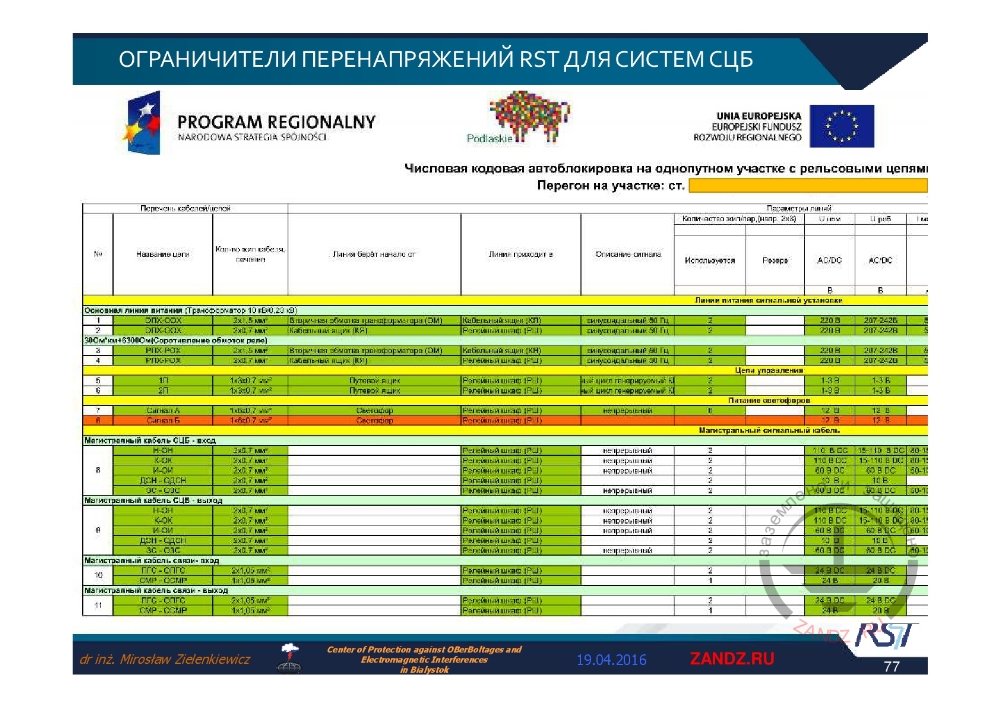
— I show which signals can take place. These are called, for example, "OPH – OOH", "RPH – ROH". Line power supply circuits are divided into main and discharge. Nominal parameters are 200 V, 50 Hz, 5A, and the cable operational capacitance is 100 nF. These parameters we have determined for all signals, and only after that we selected overvoltage protection, though, it may look simple, but installing it was troublesome.
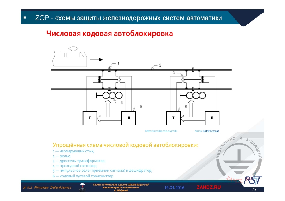
Numerical coded circuit locking
| Числовая кодовая автоблокировка | Numerical coded circuit locking |
| Автор | Author |
|
Упрощённая схема числовой кодовой автоблокировки:
|
Simplified circuit of numerical coded circuit locking:
|
— Special protection shall be selected for each automatic system on rails. I took only those examples that I have found in Internet.
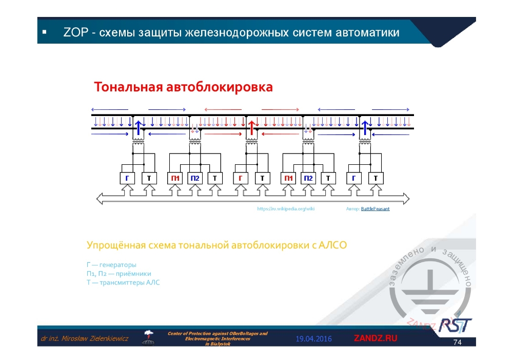
Buzzer circuit locking
| Тональная автоблокировка | Buzzer circuit locking |
|
Упрощённая схема тональной автоблокировки с АЛСО Г – генераторы |
Simplified circuit of buzzer locking with automatic train control |
| Г, Т, П1, П2 | G, T, P1, P2 |
— Each system shall be protected. If the lightning will strike a railway line, the rails will be subjected to high currents, both of conductor current and lightning current.
RST surge limiters for signals and interlocking system
| Ограничители перенапряжений RST для систем СЦБ | RST surge limiters for signals and interlocking system |
— In this case there is a set of various protection elements for Ukrainian Railways.
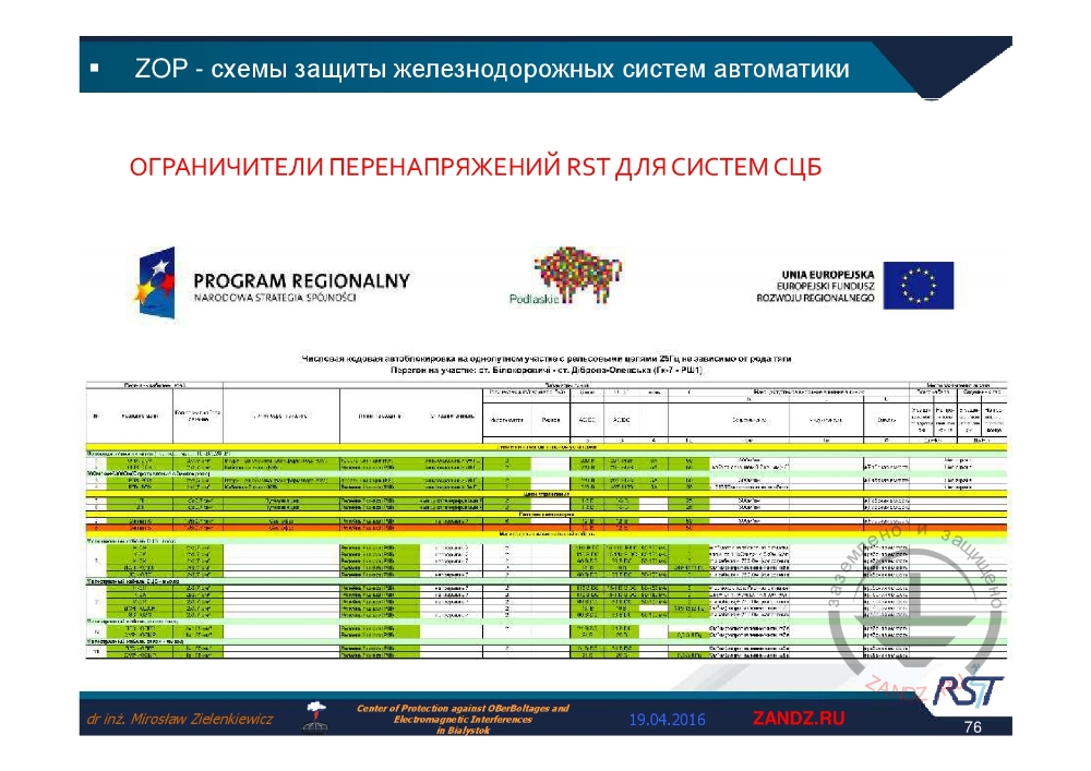
Additional funding from European Union
| Ограничители перенапряжений RST для систем СЦБ | RST surge limiters for signals and interlocking system |
— We worked on it, by using additional funds from European Union.
IsoPro B TN-C
| Ограничители перенапряжений RST для систем СЦБ | RST surge limiters for signals and interlocking system |
| Числовая кодовая автоблокировка на однопутном участке с рельсовыми цепями | Numerical coded locking at single-way section with rail circuits |
| Перегон на участке ст. | Railway section of the station |
— We should be proud of winning such a contract, and thank to one who granted money to us./p>
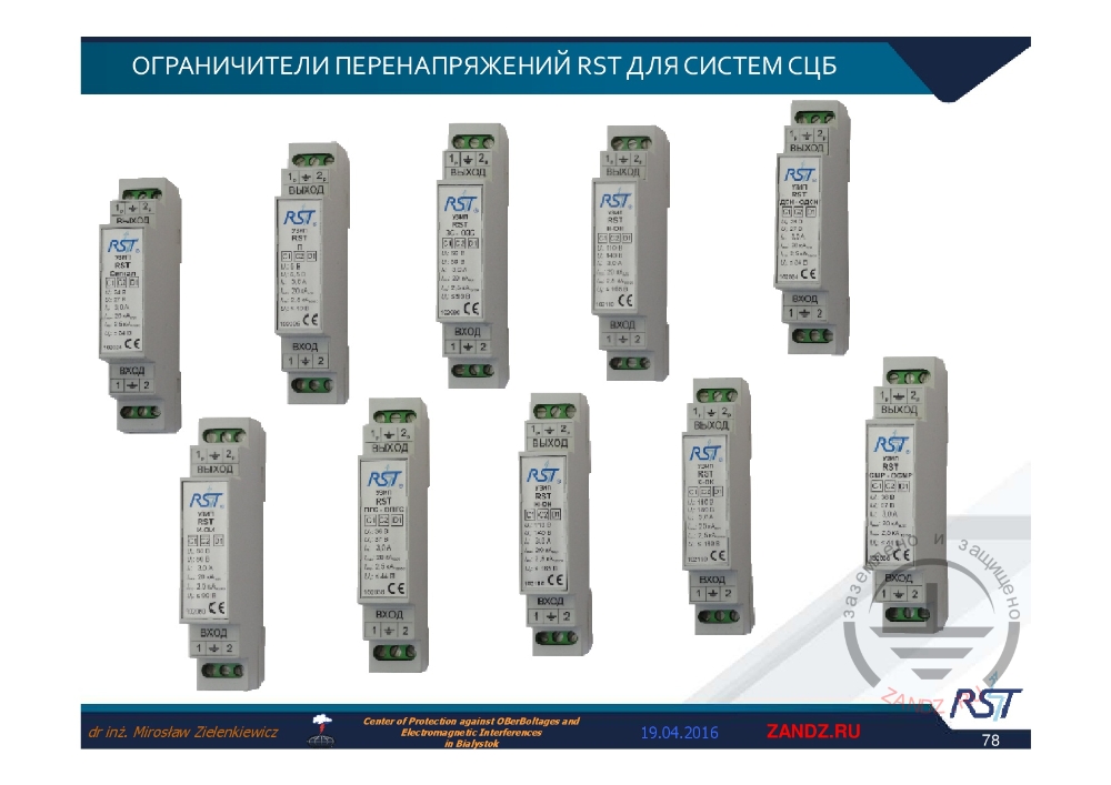
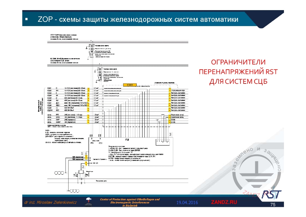
Elementary base for signals and interlocking system
| Ограничители перенапряжений RST для систем СЦБ | RST surge limiters for signals and interlocking system |
— In this elementary base we can see that each element is of a different type, in wide range.
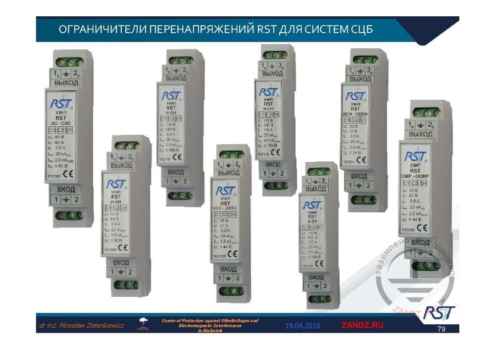
Elementary base for signals and interlocking system (continued)
| Ограничители перенапряжений RST для систем СЦБ | RST surge limiters for signals and interlocking system |
— In addition to RST, there is УЗИП ("UZIP") inscription made in Russian. There are signals of standards, which we have already mentioned.
— Refer to slide 74.
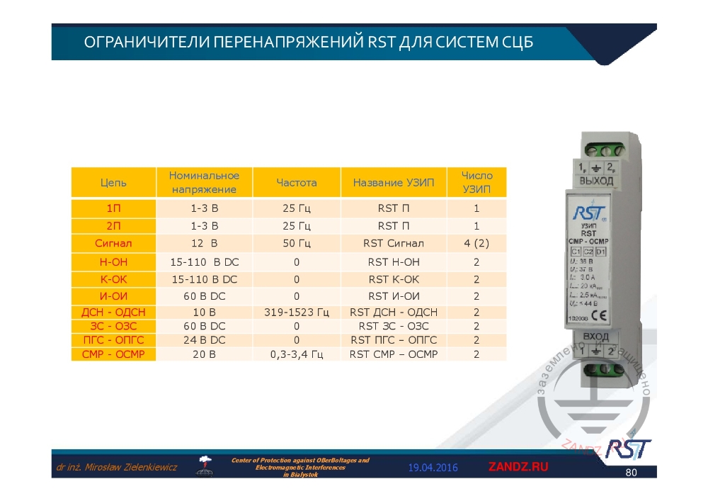
Table of technical parameters
| Цепь | Circuit |
| Номинальное напряжение | Nominal voltage |
| Частота | Frequency |
| Название УЗИП | SPD name |
| Число УЗИП | Number of SPD |
| 1П 2П Сигнал Н-OН K-OK И-OИ ДСН-ОДСН ЗС-OЗС ПГС-OПГС СМР-OСМР |
1P |
| В | V |
| Гц | Hz |
— We can select protection for any sophisticated system, for any manufacturer, including any its wishes and any electromagnetic environment, in which the element is located.
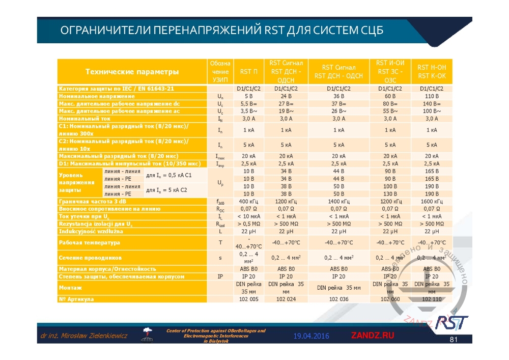
SPD selection parameters
| Технические параметры Категория защиты по IEC/EN 61643-21 Номинальное напряжение Mакс. длительное рабочее напряжение dc Mакс. длительное рабочее напряжение ac Номинальный ток C1: Номинальный разрядный ток, 8/20 мкс, линию C2: Номинальный разрядный ток, 8/20 мкс, линию Максимальный разрядный ток, 8/20 мкс D1: Максимальный импульсный ток, 10/350 мск Уровень напряжения защиты Линия-линия Линия-PE Линия-линия Линия-PE Граничная частота 3 dB Вносимое сопративление на линию Ток утечки при Uc Рабочая температура Сечение проводников Материал корпуса/Огнестойкость Степень защиты, обеспечиваемая корпусом Монтаж № Артикула |
Technical parameters |
| 35 mm DIN rail | |
| Обозначение УЗИП | SPD ID |
| Сигнал | Signal |
— Table demonstrating what we have succeeded.
Thank you for attention
| Спасибо за внимание | Thank you for attention |
— Thank you very much for being with us! May be it is now, we do start the video, Aleksei, how do you think?
— Yes, we can do it now, Miroslav. Dear colleagues, thank you for joining the webinar, if you have any questions, please, use the chat to ask them, we will wait for a while. Miroslav, thank you so much for the presentation! Dear viewers, I'm calling you to sign up and do not miss next webinars. The link has been posted in the chat. We are awaiting the questions a minute, and we should close then, if there are no questions. I see, no questions. Dear colleagues, feel free to address your questions on selection, design or calculation of the lightning protection systems after webinar to our email info@zandz.com. We should close now. Thank you for being with us. See you next time! Bye!
— Bye! Thanks a lot to everyone!
Need more information? Ask our technical experts to get reasonable answers in detail.
<< Previous page
slides from 46 to 62
Useful materials for designers:
- Webinars with the leading industry experts
- Everything for the calculation of grounding and lightning protection
- Useful materials: articles, recommendations, examples
Related Articles:
