The sixth webinar of "Surge protection" series
Webinar text. Page 3
Fast navigation by slides:
1. Limiters by RST
2. About Miroslav Zelenkevich
3. Plan of presentation
4. Sources of damages
5. Types of damages - D1: shocking living beings
6. Types of damages - D2: physical damage
7. Types of damages - D3: damage to internal systems
8. Lightning risk analysis as per IEC 62305
9. Lightning protection levels
10. Discharge protection means
11. Zonal protection concept
12. Introduction into the surge protection
13. Zonal protection concept principles
14. Normalized current pulses
15. Production of RST limiters
16. RST Limiters production stages
17. Surge limiters testing
18. Execution of documentation
19. Type tests as per IEC 61643-21
20. Test scope as per IEC 61643-21
21. Voltage limiter requirements
22. Categories of stability
23. Pulse tests in the laboratory RST
24. High-energy impact test
25. Climatic tests
26. Test oscillograms
27. Determination of limiter nominal parameters
28. Substantiation of tests
29. Example of parameters given by manufacturers
30. Parameters of SPD from other manufacturers
Page 3:
31. Example of factory test parameters
32. Example of gas limiter
33. Results before and after testing
34. Complete scheme resistance test
35. Temperature resistance test results
36. Correct parameters of limiters as per IEC 61643-21
37. Technical data of limiters
38. Surge limiters by RST
39. RST Guard series limiters
40. RST Guard surge protection device
41. RST Guard HF SPD
42. RST Guard S SPD
43. RST Guard RS485 SPD
44. RST Guard GDT and RST Guard Audio SPDs
45. RST SAP SPD
46. Nominal voltage of SPD
47. RST AL series limiters
48. Table with voltage parameters
49. RST AL HDC SPD
50. RST AL RS SPD
51. RST AL HF SPD
52. RST NET and RST CCTV BNC-1 SPDs
53. RST NET PoE SPD
54. RST CCTV BNC-1 SPD
55. CCTV SPD
56. ZOP overvoltage protection circuits
57. RST TV camera protection circuit
58. Circuits identification code
59. Damage alarm
60. RST AL TMP alarm module
61. Robotic arm protection circuit
62. Central unit protection circuit
63. Control systems protection circuit
64. Individual protection of hardware
65. Protection at LPZ zones boundaries
66. Protection of control cabinets
67. Telecommunication systems protection circuit
68. Railway automatics systems protection circuit
69. Line power supply circuits
70. Numerical coded circuit blocking
71. Buzzer circuit blocking
72. RST surge limiters for signals and interlocking system
73. Additional funding from European Union
74. IsoPro B TN-C
75. Elementary base for signals and interlocking system
76. Elementary base for signals and interlocking system (continued)
77. Table of technical parameters
78. SPD selection parameters
79. Thank you for attention
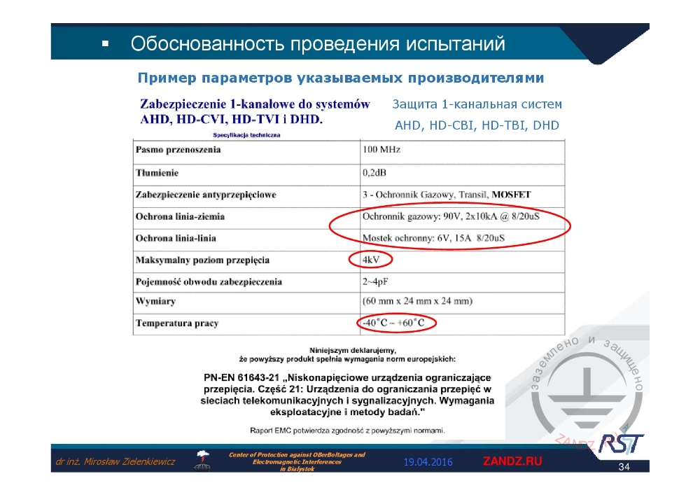
Example of test parameters given by manufacturers
| Pasmo przenoszenia | Частотная характеристика | Frequency characteristic |
| Tłumienie | Затухание | Attenuation |
| Zabezpieczenie antyprzepięciowe | Защита от перенапряжения | Overvoltage protection |
| Ochrona linia-ziemia | Охранная линия - заземление | Security line - earthing |
| Ochrona linia-linia | Охранная линия - линия | Security line - line |
| Maksymalny poziom przepięcia | Максимальный уровень скачков напряжения | Maximum voltage surge level |
| Pojemność obwodu zabezpieczenia | Ёмкость защитной цепи | Protective circuit capacitance |
| Wymiary | Размеры | Dimensions |
| Temperutura pracy C | Рабочая температура, С | Operational temperature, C |
| Ochronnik gazowy | Газовый ограничитель | Gas limiter |
| Mostek ochronny | Защитный мост | Protective bridge |
| Niniejszym oświadczamy, że powyższy produkt spełnia wymagania norm europejskich | Настоящим декларируем, что вышеуказанный продукт выполняет требования европейских норм | Hereby we declare compliance of our product with the requirements of European standards |
| PN-EN 61643-21 „Niskonapięciowe urządzenia ograniczające przepięcia. Część 21: Urządzenia do ograniczania przepięć w sieciach telekomunikacyjnych i sygnalizacyjnych. Wymagania eksploatacyjne i metody badań." | PN-EN 61643-21 "Устройства защиты от перенапряжения низкого напряжения. Часть 21. Устройства для снижения перенапряжения в телекоммуникационных и сигнальных сетях. Эксплуатационные требования и методы испытаний ». | PN-EN 61643-21 "Surge protection devices. Part 21. Overvltage limiters for teleccomunication and signal networks. Operational requirements and test methods”. |
| Raport EMC potwierdza zgodność z powyższymi normami | Рапорт ЕМС подтверждает соответствие вышеуказанным нормам | Compliance with the standards mentioned above is confirmed by EMC report |
| Защита 1-канальных систем | Single-channel systems protection |
— For example, the next element is protection of single-channel systems: AHD, HD-CBI, HD-TBI, DHD. Which single-channel protection, it is not clear. And if we just look at the parameters, we will see, that vendor gives the test parameters, but not parameters of certain elements, this is why we see "protection by anti-overvoltage", "three gas arresters", transil, it is a diode, and a "MOSFET", which is a transistor, I suppose. Protection: line – ground, arrester – 90 V, 2х10 kA – it does not comply with the standard in question at all, though later we see the wording "hereby we declare compliance of our product with the requirements of European standards" and so on and reference to the standard itself is given too. They state, that compliance with the values given above is confirmed by the compatibility report. It's just a lie, no one even tested that.
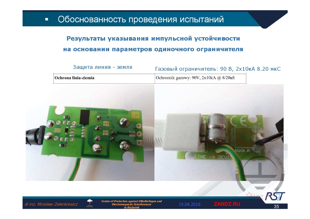
Example of gas limiter
|
Результаты указывания импульсной устойчивости на основании параметров одиночного ограничителя |
Results of specification of the pulse resistance based on the parameters of single limiter |
|
Защита линия - земля |
Protection line - ground |
|
Газовый ограничитель: 90 V, 2x10 kA, 8/20 мкс |
Gas limiter: 90 V, 2x10 kA, 8/20 µs |
— For example, there is somewhat competitor of ours on the market, it offers very cheap protection devices for CCTV. And we decided to check for ourselves, which his response will be to the parameters he indicated, as given below, if we send these to him: 90 V, 2х10 kA, 8/20 µS. As Polish, I wrote "seconds" with a capital letter. There is a circuit, and arrester is installed.
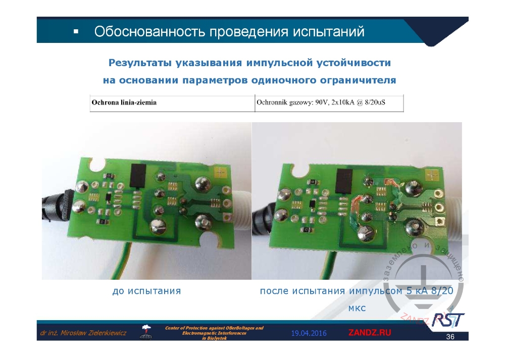
Results before and after testing
| До испытания | Before test |
| После испытания импульсом 5 кА 8/20 мкс | After test by 5 kA 8/20 µs pulse |
— Maybe the following Figure will show us, that there is an additional spark arrester. Look at the results before and after testing. You may kindly note, that the channels on the right are tending upward, and at another location it is almost welded. One more pulse, and this element will just disappear. And the pulse test was not 10 kA, but 5 kA.
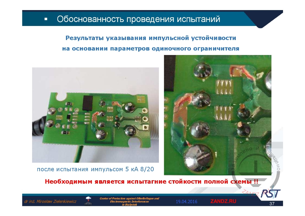
Complete circuit strength test
|
После испытания импульсом 5 кА 8/20 Необходимым является испытание стойкости полной схемы !! |
After test by 5 kA 8/20 Complete circuit resistance test is mandatory !! |
— Well, it is real practice, one shall always test the complete circuit strength, but not to specify separate elements. I think, it is quite clear.
High temperature resistance tests results
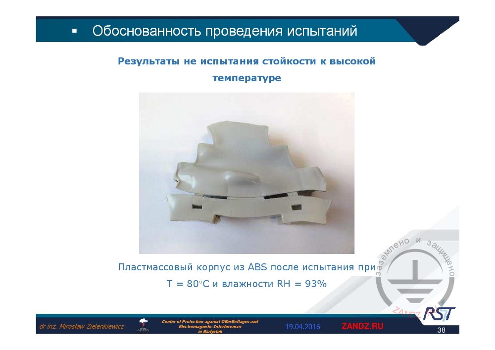
Результаты не испытания стойкости к высокой температуре
Пластмассовый корпус из ABS после испытания при T=80°C и влажности RH = 93%
Results of no testing for high temperature resistance
Plastic enclosure made of ABS after testing at T=80°C and RH = 93%
— Let us look at the tests of the first enclosure variants, that we tried to implement for our hardware. Look at the results of high temperature tests at high percent of humidity. The protection circuit is functioning normally, but how long? At what moment will the enclosure fail? Imagine, the hardware like this is installed in a cabinet near to railways, where the temperature even there, in Poland, may reach +30˚ С, heating such cabinet to 40˚ - 50˚ С inside. This is why no one can be sure in the elements quality without testing.
Correct parameters of limiters as per IEC 61643-21
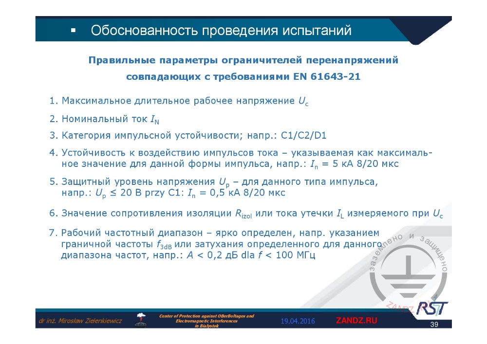
Правильные параметры ограничителей перенапряжений совпадающих с требованиями EN 61643-21
1. Максимальное длительное рабочее напряжение Uc
2. Номинальный ток IN
3. Категория импульсной устойчивости; напр.: C1/C2/D1
4. Устойчивость к воздействию импульсов тока – указываемая как максимальное значение для данной формы импульса, напр.: In = 5 kA 8/20 мкс
5. Защитный уровень напряжения Up – для данного типа импульса, напр. Up ≤ 20 V at C1: In = 0.5 kA 8/20 мкс
6. Значение сопротивления изоляции Rizol или тока утечки IL измеряемого при Uc
7. Рабочий частотный диапазон - ярко определё, напр. указанием граничной частоты f3dB или затухания определённого для данного диапазона частот, напр.: A<0.2 dБ dia f < 100 MГц
Correct parameters of overvoltage limiters complying with the requirements of EN 61643-21
1. Maximum continuous operational current Uc
2. Nominal current IN
3. Category of pulse resistance; e.g.: C1/C2/D1
4. Resistance to current pulses – specify as the maximum value for that pulse form, e.g.: In = 5 kA 8/20 µs
5. Protective level of voltage Up – for this pulse type, e.g.L Up ≤ 20 V at C1: In = 0.5 kA 8/20 µs
6. Value of insulation resistance Rizol or leakage point IL measured at Uc
7. Operating frequency range is determined expressly, e.g. by specifying the limit frequency f3dB or attenuation specified for that range of frequency, e.g.: A<0.2 dB at f < 100 MHz
— What elements in fact shall we select, test and specify, as the manufacturer who comply with the requirements of standard EN 61643-21. First, maximum continuous operational voltage, in order to be sure, that our element will withstand that nominal voltage, when we put it into the protected line. You shall know its nominal current, for the elements not to fail, when connected serially in our circuit. One shall test and specify, which categories of pulse resistance are specific for the hardware, because category D1 allows us installing the element on the boundary of external and internal zone. The current pulse here is 10/350 µs. And here you are the induced pulses, which allow using the circuit inside the object, that is to say, these make the pulse form of 8/20 µs. Check the current pulse resistance, specify the maximum value for this pulse form. For example, In = 5 kA, 8/20 µs. We check protective level of the voltage for this type of pulse. If we specify that U limitations are lower or equal to 20 V, and not higher as it was before, then one is to remember, it shall be less or equal to 20 V for the category С1 at the current 500 А, 8/20 µs. Then, the designer understands, that this element, in case of category C1 inside the object, shall be for the second zone, and not the first zone, it provides limitation at 500 A up to 20 V, which normal signal line circuits generally withstand. The values of insulation resistance or current leakage, that we also measure at continuous operational voltage.
Technical data of limiters
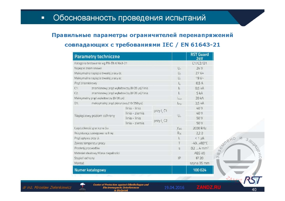
Parametry techniczne
Kategoria testowania wg-PN-EN 561643-21
napięcie znamionowe
maksymalne napięcie trwalej pracy dc
maksymalne napięcie trwalej pracy ac
prąd znamionowy
С1: prąd znamionowy wyladowczy
С2: prąd znamionowy wyladowczy
napięciowy poziom ochrony
D1 maksymalny prąd piorunowy
linie - linie
linie – żernia
napięciowy poziom ochrony
częstotliwość graniczna 3 dB
rezystancja szeregowa na linię
prąd upływu przy U
Zakres temperatur pracy
Przekrój przewodów
material obudowy/klasa niepalności
Stopien ochrony
Montaż
Numer katalogowy
Szyna 35 mm
Технические параметры
Категория тестирования wg-PN-EN 561643-21
номинальное напряжение
максимальное постоянное напряжение постоянного тока
максимальное напряжение постоянной работы переменного тока
номинальный ток
C1: номинальный разрядный ток
C2: номинальный разрядный ток
уровень защиты по напряжению
D1 максимальное значение импульсного тока
линия-линия
линия-земля
уровень защиты по напряжению >
предельная частота 3 дБ
последовательное сопротивление на линии
ток утечки на U
Диапазон рабочих температур
Сечение проводников
материал корпуса / класс невоспламеняемости
Степень защиты
Сборка
Номер в каталоге
Шина 35 мм
Technical parameters
Category of testing wg-PN-EN 561643-21
Nominal voltage
Maximum continuous voltage of direct current
Maximum continuous operational voltage of alternating current
Nominal current
C1: nominal discharge current
C2: nominal discharge current
Voltage protection level
D1 maximum pulse current value
Line-line
Line-ground
Voltage protection level
Limit frequency of 3 dB
Serial resistance on the line
Leakage current at U
Operational temperature range
Cross-section of conductors
Material of enclosure / non-inflammability class
Protection degree
Assembly
Number in catalogue
35 mm bus
— Here you can see all the parameters we discussed above, as taken from the technical data of our elements catalogue, and all these comply with the standard EN 61643-21.
Surge limiters by RST
| Ограничители перенапряжения производства RST | Overvoltage limiters by RST |
— Which limiters we decided to manufacture in-house? How we determined it?

RST Guard series limiters
|
Линейка RST Guard |
RST Guard Line |
|
УЗИП серии RST Guard |
RST Series SPD |
|
|
— First, we sell protection of CCTV systems for many years. These systems have become sensitive to the surge pulses about 15 to 17 years ago. And for general applications, we developed the range of products and named it RST Guard, where "Guard" refers to protection in some languages. Here we can list the RST Guard series: RST Guard HF, RST Guard S, RST Guard GDT, RST Guard Audio, RST Guard RS485. The names indicate, that this standard element is intended for higher frequencies. The special-purpose one, that includes gas arrestors for Audio systems and for the RS485 buses pulse standards. All elements are tested for categories C1/C2/D1. These are mounted by means of 35mm-width DIN rail. These feature higher impact strength: 20 kA, 8/20 µs and 3.5 kA, 10/350 µs.
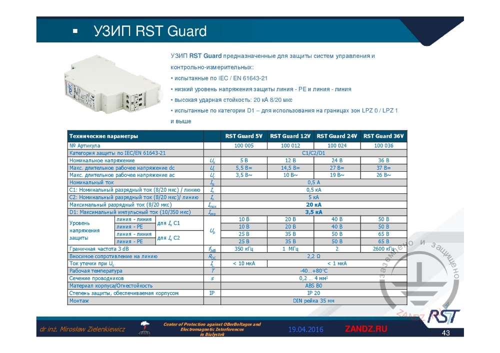
RST Guard SPD
|
УЗИП RST Guard |
RST Guard SPD |
|
УЗИП RST Guard преднозначенные для защиты систем управления и контрольно измерительных:
|
RST Guard SPD designed for protection of Instrumentation and control systems:
|
|
Технические параметры |
Technical parameters |
|
Уровень напряжения защиты |
Protective voltage level |
|
Линия-линия |
Line-line |
|
Граничная частота 3 dB |
Limit frequency 3 dB |
|
DIN рейка 35 мм |
35 mm DIN rail |
|
для |
for |
— Too small view. I used a magnifying glass tool, setting 70% view, it has become bigger, however, because of there are many slides, I further will not zoom it in, in order to avoid the problems with the presentation. RST Guard is designed for protection of the instrumentation and control systems, it also features low protective voltage. Protection: line – ground, here it is indicated as РЕ, and line – line. Please, look at the protective voltage level: line – line, line - РЕ and here we can see very low voltages, it means that the last step includes low-voltage diode, which has high strength. It provides very good results. According to tests for category D1 it is to be used at the boundary LPZ 0/ LPZ 1. The next element with high operational frequency. Let us look again to that element, and see, that its operational frequency values are for the low-voltage element, usually, the minimum frequency is 350 kHz, and higher the voltage limit, lower the semiconductor capacitance, the attenuation is of 1 MHz, 2 MHz and 2.6 MHz. "kHz" are specified there, sorry for having not changed yet.

RST Guard HF SPD
|
УЗИП RST Guard HF преднозначенные для защиты систем более высоких частот:
|
RST Guard HF SPDs are designed for protection of high frequency systems:
|
|
Технические параметры |
Technical parameters |
|
Уровень напряжения защиты |
Protective voltage level |
|
Линия-линия |
Line-line |
|
Граничная частота 3 dB |
Limit frequency 3 dB |
|
DIN рейка 35 мм |
35 mm DIN rail |
— Let us look at the next element with HF code. It is designed for protection of systems with higher frequency. Over 70 MHz, according to the parameters. By looking at other parameters, we will find high impact strength of 20 kA and these are tested for C1, C2. The maximum current, namely, instantaneous, is 20 kA and the lightning pulse current is 3.5 kA. Very high strength. Therefore, we may apply zero and one at the external and internal zones boundary. By looking through the data, we see the line resistance is indicated here. The resistance is about 2.2, which two following protection steps are based on, as well as there are certain current limitations at relevant moment. Nominal voltage of our systems shall be 5 Volts, 12 Volts, 24 Volts.
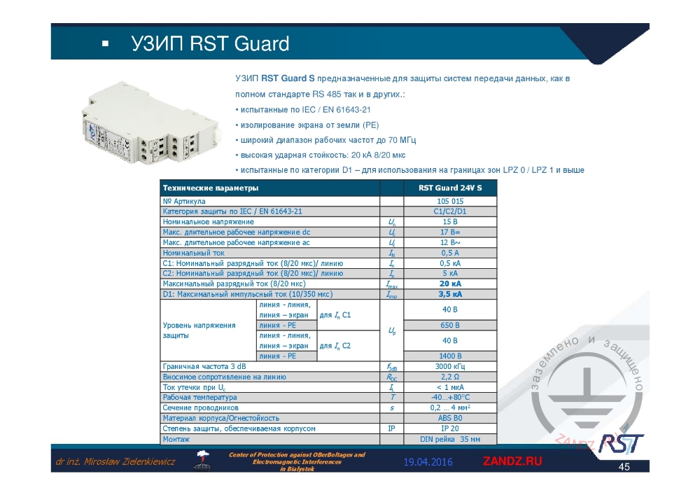
RST Guard S SPD
|
УЗИП RST Guard S предназначенные для защиты систем передачи данных, как в полном стандарте RS 486 так и в других:
|
RST Guard S SPD is designed for protection of data transfer systems, both in complete standard RS 486 and in others:
|
|
Линия – линия |
Line – line |
— The next RST Guard S element is designed for the data transfer systems protection, according to complete RS 485 standard and to other similar standards. Its parameters are similar in terms of frequency. The difference is, according to what is indicated here, is the insulated grounding shield. If we want to ground the shield, we shall make this additionally. The value of nominal voltage is 24 V, I'm sorry, 15 V are indicated erroneously.
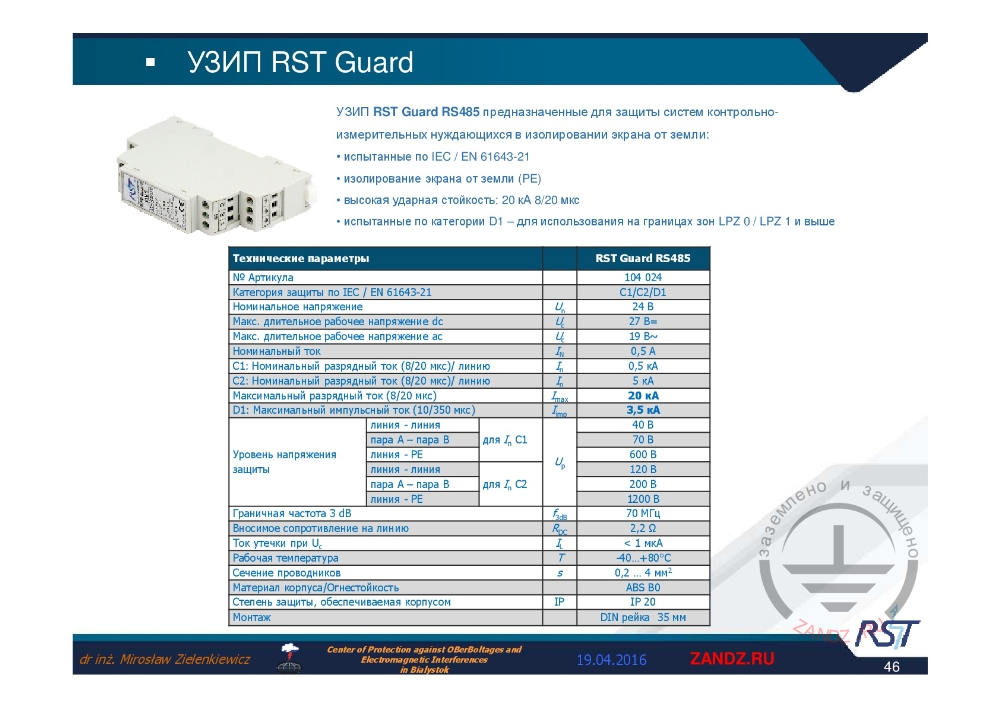
RST Guard RS485 SPD
|
УЗИП RST Guard RS485 предназначенные для защиты систем контрольно-измерительных нуждающихся в изолировании экрана от земли:
|
RST Guard RS485 SPD designed for protection of instrumentation and control systems requiring shield insulation from the ground:
|
|
Линия – линия |
Line – line |
— Next special element RS 485 is S like. It is designed especially for that standard. Similar parameters, here the nominal voltage of 24 Volts is indicated correctly. The limitation voltage in this case is 40 V to 70 V between the lines, and line to ground of 600 V. We can see, that there is an arrester installed. It is safe for that location: line – ground, even can be 1.2 kV between the line and РЕ. The best frequency is below 70 MHz and the resistance of 2.2 Ω. The leakage current is quite high due to diodes, it is about, or to be more correct, not higher than 1 µA. General parameters are the same. Here I shall note the value of conductors to be connected, as given in this line from 0.2 to 4 mm2.
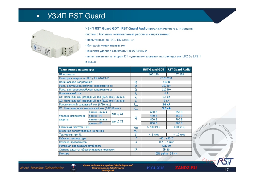
RST Guard GDT and RST Guard Audio SPDs
|
УЗИП RST Guard GDT and RST Guard Audio предназначенные для защиты систем с большим номинальным рабочим напряжением:
|
RST Guard GDT and RST Guard Audio SPDs designed for protection of systems with high nominal operational voltage:
|
— RST Guard GDT and RST Guard Audio are designed for protection. RST Guard GDT class with high nominal operational voltage. These elements are difficult in manufacture and tests, this is why not all manufacturers provide them. Note, that if the RSTGuardAudio system is of 110 V, then one shall always refer to which is the maximum continuous voltage. Based on the practice, it is 130 V. This is why our element will not be actuated in this case, because its maximum voltage is 150 V. Such elements here feature very high nominal voltages of 6 A, it is too high for the signal lines, but this system has "Audio" designation, to handle such currents and the impact currents are similar, as before, that is to say these are identical, very high, of 2.5 kA and the pulse of 10/350 µs. 5 kA is nominal current, for category С2 the maximum is 20 kA.
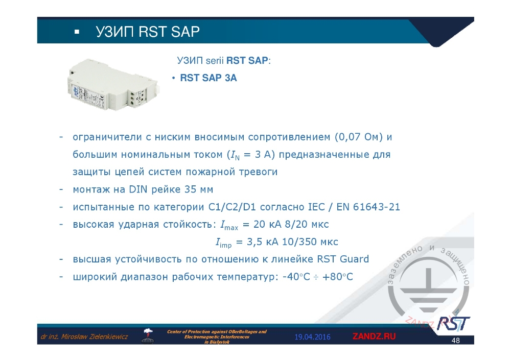
RST SAP SPD
УЗИП series RST SAP:
- RSP SAP 3A
- ограничители с низким вносимым сопротивлением (0.07 Ом) и большим номинальным током (IN = 3 A) предназначенные для защиты цепей систем пожарной тревоги
- монтаж на DIN рейки 35 mm
- испытанные по категории C1/C2/D1 согласно IEC / EN 61643-21
- высокая ударная стойкость: Imax = 20 kA 8/20 мкс
Iimp = 3.5 kA 10/350 мкс
- высшая устойчивость по отношению к линейки RST Guard
- широкий диапазон рабочих температур: -40°C to +80°C
RST SAP series SPD:
- RSP SAP 3A
- limiters with low insert resistance (0.07 Ω) and high nominal current (IN = 3 A) designed for protection of fire alarm systems
- for 35mm DIN rail mounting
- tested for categories C1/C2/D1 according to IEC / EN 61643-21
- high impact strength: Imax = 20 kA 8/20 µs
Iimp = 3.5 kA 10/350 µs
- higher strength compared to the RST Guard range
- wide range of operational temperatures from -40°C to +80°C
— If we see the limiters indicated as SAP, this refers to alarm systems protection. "SAP" refers to a fire-fighting system in Polish. The limiters induce very low resistance, of about 0.07 Ω, because one shall note, that these elements are connected to the line, where the alarm elements are connected serially. This is why we may not connect the elements with high resistance. Such element has also a high nominal current which is specific for fire circuits. As before, it is mounted by means of 35mm DIN rail. Impact parameters of 20 kA, 8/20 µs and 3.5 kA, 10/350 µs are very high. Higher resistance in comparison with RSTGuard range, a wide range of operating temperature from -40˚С to + 80˚С.
<< Previous page
slides from 16 to 30
Next page >>
slides from 45 to 62
Useful materials for designers:
- Webinars with the leading industry experts
- Everything for the calculation of grounding and lightning protection
- Useful materials: articles, recommendations, examples
Related Articles:
