Task:
Object: chapel.
Soil: clay loam.
Soil resisitivity: 100 Ohm*m
Solution
The activities were carried out in accordance with the EIC 7 th ed. Chapter 1.7. IS 153-34.21.122-2003 "Instructions for lightning protection of buildings, structures and industrial communications" (hereinafter IS) and AD 34.21.122-87 "Instructions for lightning protection of buildings and structures" (hereinafter AD).
The chapel is a traditional structure in terms of lightning protection according to IS and belongs to category 3 according to AD.
Protection of buildings against lightning strikes is carried out by lightning rods. A lightning rod presents itself a device rising above the protected facility to divert the lightning current into the ground without entering the protected facility. It consists of a lightning rod directly perceiving the lightning discharge, down conductor and ground electrode system. A metal cross acts as a lightning rod.
The complex of measures to ensure necessary requirements for the lightning protection system is represented by the following solutions:
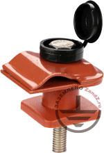
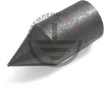
- connection of two down conductors to the metal cross on the dome is carried out by means of clamps ZZ-005-064;
- Laying of two down conductors with the use of copper-bonded wire D = 8 mm to the grounding device. The down conductors should be located not closer than 3 m from entrances or in places where people cannot touch them. Fixation of down conductors on the roof is carried out with the help of GL-11747A clamps. Fixation of a down conductor to vertical surfaces is carried out with the help of clamps GL-11703A;
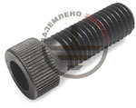
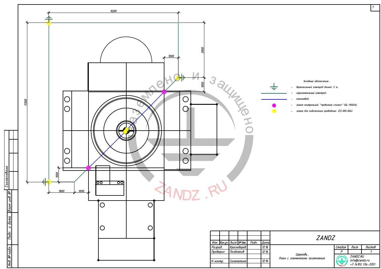
- installation of the grounding device, consisting of three vertical electrodes (copper-bonded rods,14 mm in diameter) 3 m long, united by a horizontal electrode (copper-bonded tape 4x30 mm). The distance between the vertical electrodes is at least 5 meters, the distance from the horizontal electrode to the building walls is 1 m, the depth is 0.5 m;
- the grounding device is used for lightning protection and fits for usage in permafrost ground. It should be united to the grounding device of protecting grounding;
- the down conductor is connected with the copper-bonded tape termination from the ground with the help of GL-11562A clamp.
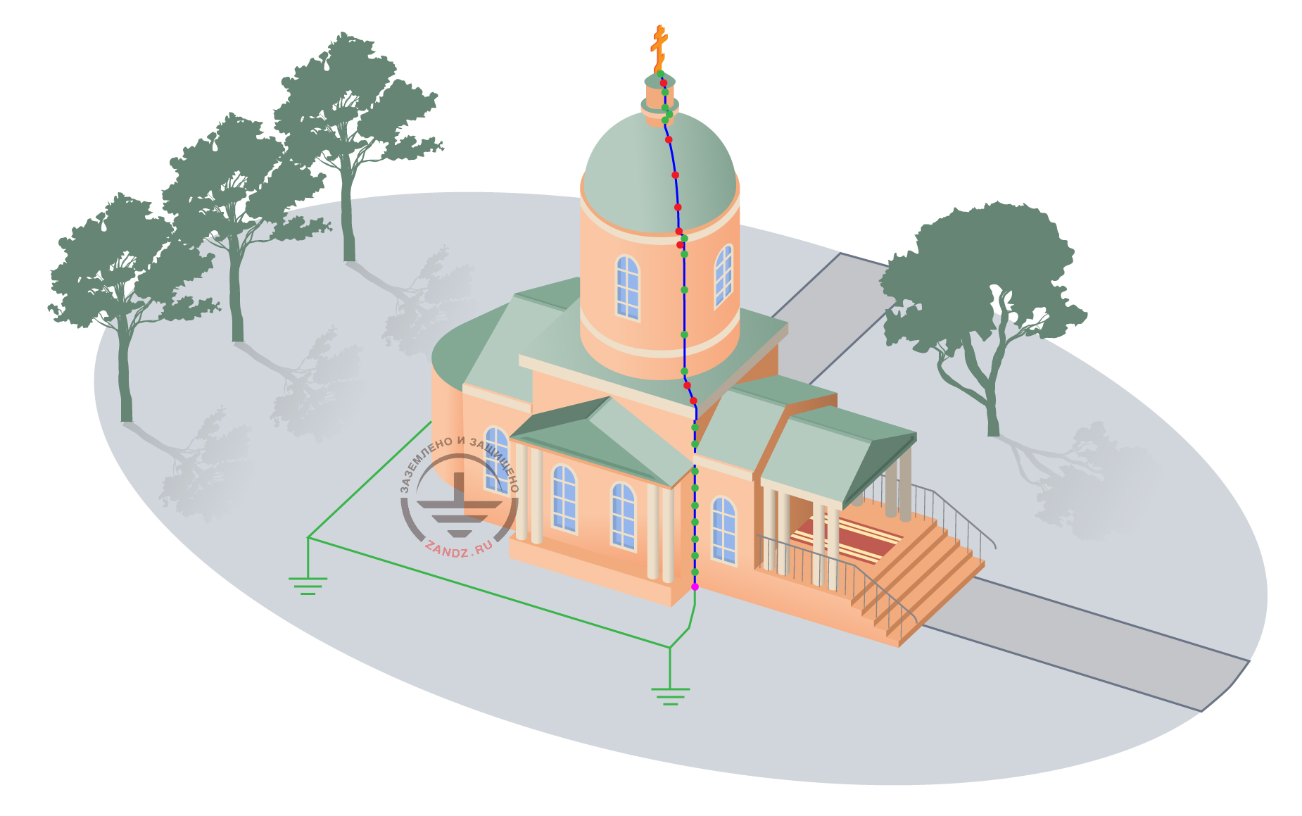
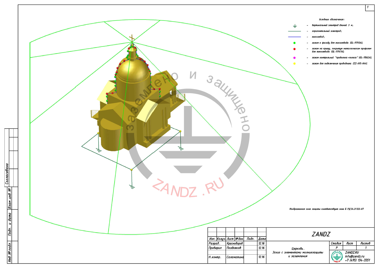
Arrangement of elements of lightning protection is shown in Figures 1 and 2. Protection zone corresponding to zone B of the AD, is shown in Figure 3.
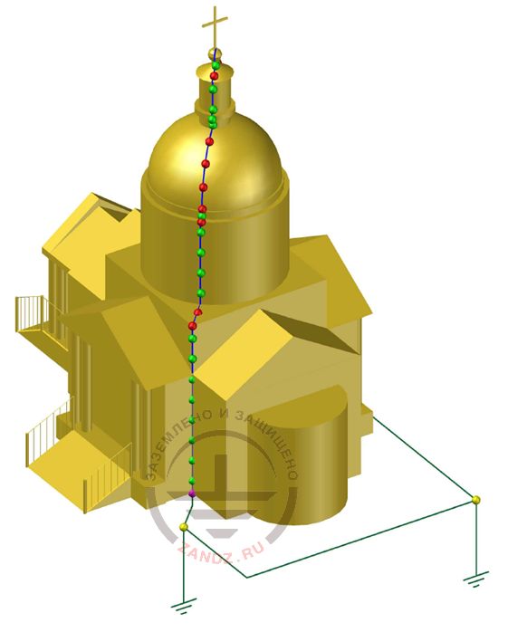
Figure 1 - Chapel lightning protection elements layout (View 1)
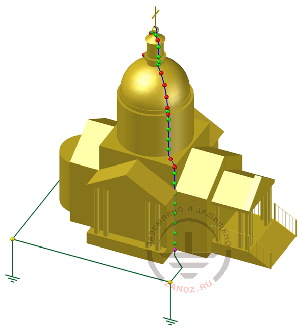
Figure 2 - Chapel lightning protection elements layout (view 2)
Notation:
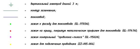
Вертикальный электрод длиной 3 м – vertical electrode 3 m long
Контур заземления- grounding contour
Токоотвод – down conductor
Зажим к фасаду для токоотвода – clamp to the façade for the down conductor
Зажим на крышу , покрытую металлическим профилем для токоотвода –clamp for the roof covered with metal profile for down conductor
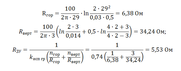
Зажим контрольный «проволока+ полоса» - control clamp “wire+tape”
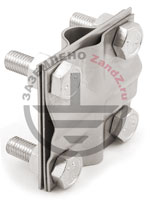
Зажим для подключения проводника – clamp for connecting conductor

Figure 3 - Protection zone
The chapel is completely under the protection zone.
Calculation of a grounding device
In accordance with the
Lightning protection is calculated using the software developed by JSC "Energy Institute to the name of G. M. Krzizhanovsky" (JSC "ENIN").
Specific soil resistance of clay loam is taken equal to 100 Ohm ∙ m.
Horizontal electrode resistance:
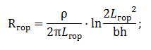
ρ - soil resistivity, Ohm* m;
b - horizontal electrode tape width,m;
Lгор - horizontal electrode length, m.
Vertical electrode resistance:
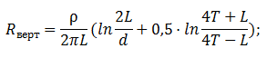
Where p - soil resistivity, Ohm-m;
L - vertical electrode length, m;
d - vertical electrode diameter, m;
T - deepening - the distance from the ground surface to the ground electrode, m;
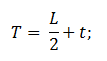
where t - deepening of the electrode top, m
Grounding device impedance:
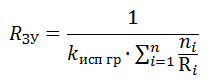
where n - number of kits;
Kисп - utilization ratio;
The design resistance of the grounding device is 5.53 ohms, which is less than the required value of 10 ohms.
See the order of modular grounding installation at the link.
The list of required materials:


Internal lightning protection (SPD)
For the protection of equipment and electric communications inside the buiding we recommend to foresee the set of measures allowing to exclude the impact of dangerous overvoltages.
Protection of the electrical system. Protection in the distribution panel
Surge Protection Device (SPD) of I+II+III PP BCВ TNS 25/100 class is installed in the main distribution panel. It protects from pulse overvoltages. It is chosen according to the three-phase input into the house and TN-C-S or TN-S power system.
The connection is carried out successively (V-connection). We recommend to use fuzes F1 (see the scheme) without skewing, with the nominal up to 125 A.
If a local switch (or protective fuses instead of it), designed for the electricity mains load, and its nominal is less than 125 A, then installation of additional fuses F1 is not required.
SPD connecton diagram is shown in Figure 4.
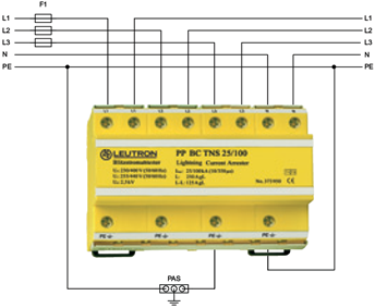
Figure 4 - SPD connection diagram
Equipment used:
| № | Image | Product item | Name | Quantity, pcs. |
| 1 |  |
LE-373-960 | LEUTRON Surge protection device (SPD) PP BCD TNS 25/100 | 1 |
Lightning protection of the object is considered incomplete without the indicated measures, because only application of protective devices allows to reduce overvoltages in the electricity mains to the level safe for the equipment under protection.
Appendix: the project is available in DWG and PDF formats
Do you need to make the project on grounding and lightning protection? Order it by contacting the ZANDZ Technical Center!
Related Articles:
