From the series of articles "Lightning protection of oil and gas facilities".
2.1 Regulatory requirements
Here, again, we have to omit the instructions of IS-153-34.21.122-2003, which does not contain any specific requirements to grounding of lightning rods. The AD 34.21.122-87 formally formulate the requirements, but they concern not the value of ground resistance, but the design of grounding devices. For separate lightning rods we are talking about the foundations of their supports or a special ground electrode system, the minimum dimensions of which are shown in Fig. 7.
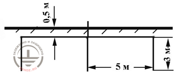
Figure 7. The minimum dimensions of the ground electrode of a horizontal tape and three vertical rod electrodes according to AD 34.21.122-87
There is no indication of change in the size of the electrodes, depending on the soil resistivity in the standard. This means that according to the compilers, a standard facility is suitable for any soil. How in this case will change its grounding resistance Rgr can be judged by the calculated data of Fig. 8.
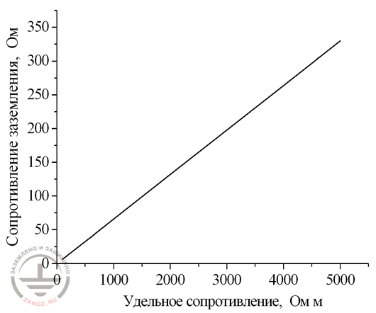
Figure 8. Estimated value of the ground resistance of a typical ground electrode from AD 34.21.122-87
Сопротивление заземления, ом – ground resistance, ohm
Удельное сопротивление, ом м- conductivity, ohm m
Changing the value of Rgr within almost 2 orders of magnitude can hardly be considered as normalization. In fact, there are no specific requirements to the value of ground resistance in the standard and this issue certainly deserves special consideration.
The standard of "Transneft" JSC surprised by the table of normalized values of lightning rods' ground resistance (Fig. 9) that the compilers completely copied from the latest edition of the EIC, where it refers to the ground electrodes of the poles of HV lines of 110 kV and higher. Strict requirements of the EIC are quite understandable, because the resistance of the HV support ground resistance largely determines the amount of lightning overvoltage on the line insulation. The motives of the transfer of these requirements to the grounding of lightning rods are impossible to be figure out, especially because in high-ohmic grounds they cannot be carried out using any reasonable constructions. To illustrate this, in Fig. 10 you see the results of the calculation of grounding of lightning rod of an absolutely fantastic performance. It is a completely metal design of square section, the side length of which is indicated on the x-axis. Two variants are calculated - with a depth of laying into the ground to 3 and 10 m. It is easy to see that in the ground with resistivity ρ = 5000 ohm m the normalized value of 30 Ohms (Rg/ Ρ = 0,006 m-1) it will be necessary to fill the neighborhood of the foundation of the lightning rod with metal to more than 50x50 m. The situation with an extended ground electrode is no better. Under the same conditions to provide the required ground resistance a horizontal bus with the length of 450 m is required.
|
Equivalent soil |
The highest permissible grounding resistance |
|
Up to 100 |
10 |
|
More than 100 to 500 |
15 |
|
More than 500 to 1000 |
20 |
|
Over 1000 to 5000 |
30 |
|
Over 500 |
6*10-3 |
Table 9
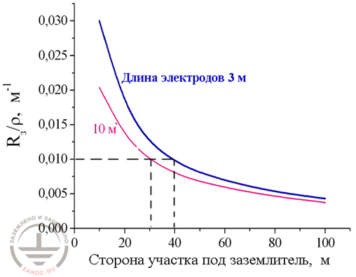
Figure 10. To the estimation of JSC "Transneft" standard requirements using a focused grounding device
Длина электродов 3 м – electrodes’ length, m
Сторона участка под заземлитель, м- side of the site for the ground electrode, m
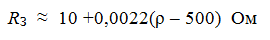
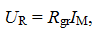
The requirements of "Gazprom" JSC are extremely specific. The grounding resistance of a separate lightning rods for the I and II levels of protection should be equal to 10 ohms in soils with p ≤ 500 Ohm m. In high-resistance soils it is possible to use ground electrodes, the resistance of which is defined as
Realizing the complexity of producing of such a relatively low ground resistance, the standard recommends a chemical treatment or partial replacement of soil. The estimation of volume of recommended work in specific conditions requires special attention. It is easy to perform for the simplest situation, focusing on a hemispherical ground electrode, the potential of which in two-layer ground (regardless of what has been done - chemical or mechanical replacement of the ground) according to Fig. 11 is equal to
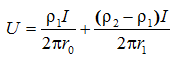
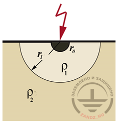
Figure 11. To the estimation of ground resistance in two-layer soil
An accurate value of ground resistance is defined as
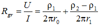
In the extreme case when the chemical treatment or replacement of soil proved to be so effective that its resistivity dropped to almost zero,

The expression allows the radius r of the treatment1 from the bottom. In this example, it is equal to about 40 m, which corresponds to the volume of soil around 134,000 m3. The resulting value forces to very seriously think about the reality of the planned operation.
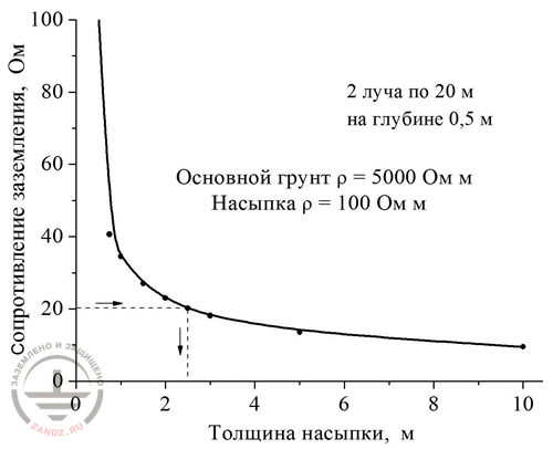
Figure 12. Ground resistance of two-beam horizontal ground electrode depending on thickness of the top of the treated soil layer.
Сопротивление заземления , ом – ground resistance, ohm
2 луча по 20 м на глубине 0,5 м – two beams 20 m each at the depth of 0,5 m
Основной грунт – main soil
Насыпка – soil filling
Толщина насыпки – thickness of the filling
The assessment brings to the similar result and for virtually any other significant design of ground electrodes, for example for two-beam ground electrode system of horizontal buses of 20 m each, the calculated dependence in Fig. 12 allows to estimate how changes the ground resistance of of such a construction at the change of the thickness of upper low-resistance layer of soil-ohmic replaced soil. The required ground resistance of 20 ohms is obtained at the thickness of treated (or replaced) layer of 2.5 m. It is important to understand at what distance from the ground electrode the processing can be stopped. The potential at the ground surface is the indicator U (r). Chang of resistivity ceases to influence the outcome, where the potential U (r) is much less than the capacity of the ground electrode Ug = U (r0).
2.2. For what purpose a lightning rod is grounded
Please do not assume this section title banal. Lightning rods have been grounded ever since their invention, otherwise they could drain the lightning current into the ground. Current guidelines suggest that grounding resistance should provide safe drainage of the lightning current. What kind of danger and safety they mean? We can't be banal here. Probably, it is necessary to recall the overhead power lines once again. The ground resistance there determines the resistive component of lightning overvoltage which affect the string of insulators.
Lightning rods have nothing like that. Their lightning arrester accepts the potential of the grounding electrodes "without any problem". The presence of a finite ground resistance does not affect the ability of the lightning rod to attract lightning. The laboratory test sought to trace the influence of ground resistance to this process, and each time without any result. The explanation is quite simple and obvious. Lightning never strikes into the lightning rod. It is met and attracted by the plasma counter discharge channel, which starts from the top of the lightning rod in the electric field of a thunderstorm cloud and a charge of an already emerging lightning. This channel (it is called counter-leader) is developing at a current of not more than tens of amperes. The voltage drop from such a weak current on lightning rod ground resistance is little significant compared to the order of the potential 107 -108 V that is carried by the lightning from a thunderstorm cloud. Indeed, at the ground resistance of 10, 20, 100 or 200 ohm the voltage on the ground electrode from the current ~ 10 A will not exceed even 104 V - the negligible value compared to what the lightning has.
A separate lightning rod, as we know, is used for the only purpose - to eliminate the spread of the lightning current on metal structures of the protected object. It is for this very specific reason, certain distances from the lightning rod to the object over air and the ground are selected. Let us assume that they are chosen correctly and really eliminate spark overlaps. Nevertheless, the current gets into the object ground electrode system and its share is quite significant, especially when the function of its grounding is carried out by a large-square foundation of the protected structure. Calculated data in fig. 14 show this proportion depending on the distance between the ground electrodes. For the lightning rod it is performed as prescribed by AD 34.21.122-87 in the form of a horizontal tape 10 m long with 3 vertical bars 3 m each; the foundation of the object has a size of 50x50 m and it is deep laid to 3 m. Computer calculations were performed for a homogeneous soil, and in the case where the surface layer of the ground soil is replaced to 2,5 m by highly conductive soil with resistivity of less than 50 times. It is easy to make sure that the insulation distance of 5 m, as prescribed by the standard of JSC "Transneft", little prevents the penetration of lightning current to the object through the soil, especially if its top layer is replaced or chemically treated. Even at the distance of 15 m, normalized by the standard of JSC "Gazprom", the current in the ground electrode of the object exceeds 50%.
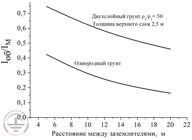
Figure 14. The share of the lightning current penetrating the ground electrode system of the object via a conductive connection to the ground electrode of the lightning rod, depending on the distance between them
Двухслойный грунт – two layer soil
Толщина верхнего слоя – upper layer thickness
Однородный грунт – homogenous soil
Расстояние между заземлителями, м – distance between ground electrodes, m
Here it is necessary to underline once again that any processing of the upper soil layer, reducing the ground resistance, not only reduces the conductive connection between the lightning rod and oshare of the lightning current, branched off into the object.
It's time to ask once again about the purpose of reducing ground resistance. The two aspects of the problem remain untouched - the formation of spark channels and step voltage. The first question will be examined below in a separate section. As for the step voltage, it certainly depends on the design of ground electrode system of the lightning rod and on its ground resistance. The calculated curves in Fig. 15 show the dynamics of step voltage reduction with increasing distance from the typical lightning rod ground electrode prescribed by the Regulations AD 34.21.122-87 (see. explanations to Fig. 14).
2.3. How to design
The task to satisfy regulatory requirements without unnecessary material costs is set in the section. This is all the more important that the value ground resistace of lightning rod poorly affects the quality of lightning protection. Anyway, those dangerous effects of lightning, which may lead to a catastrophic situation in the tank farm, or any other object of hydrocarbon fuel reprocessing are not directly connected with it. The main desired thing is to avoid costly chemical treatment or replacement of large amounts of soil and comply with industry standards on lightning protection without them.
It is reasonable to make a ground electrode for each lightning rod only in soils with low resistivity, where even the standard design of the AD 34.21.122-87 is quite capable. For example, at the recommended length of horizontal bus of 12 m and 3 vertical bars of 5 m each, ground resistance in the soil with resistivity ρ is equal
This means that if ρ ≤ 300 ohm m the calculated value does not exceed 20 ohms. At higher soil resistivity a good result is provided by 4 mutually perpendicular beams. At the length of 20 m each, ground resistance is equal to
and the installation of 5-meter-vertical rods at the ends of each beam reduces this value to
The problem becomes serious when the soil resistivity is considerably greater than 1000 ohm * m. Here the organization of a common grounding contour for all separate lightning rods attracts attention. We should once again refer to Fig. 4, which demonstrates the protection of the tank farm with 3 wires 100 meters long, with the distance between the parallel wires of 50 meters. Unification of their supports with horizontal buses forms a grounding contour with two cells 100x50 m. Its ground resistance at the installation of buses to the depth of 0.7 m provides
which allows to solve the problem in the ground with resistivity of 3000 ohm * m, even guided by the standard prescription of JSC "Gazprom". It is pertinent to note that additional local ground electrode system at every lightning rod almost does not affect the ground resistance of the ground contour as a whole. Thus, the use of each foundation support with metal reinforcement 5 m long and equivalent radius of 0.2 m as a local ground electrode for every lightning rod (Rgr ≈ 0.1ρ [ohm]) in the system of 6 supports it reduced the overall resistance of the ground contour to only 6%. The reason for this weak influence lies in the effective screening of rods by extended horizontal buses. Lengthening horizontal buses connecting supports of lightning rods, may give a chance to get ground resistance of about 20 ohms in the ground with a resistivity of 5000 ohm.
The reader has the right to terminate the description of such bright prospects, recalling that a long bus slowly enters the process of pulse current spreading due to its induction coefficient. It can't be objected. But at least two circumstaces are still in favor of the proposed solution. Firstly, none of the mentioned standards requires any specific values of pulse ground resistance, and secondly, in the high-resistance soils, the of the pulse current to the grounding bus is quite high and that is why the current value of the ground resistance Rgr(T) = Ugr(T) / iM(t) quickly takes the final value, controlled by the regulations. As an example in Fig. 16 you see the dynamics of change of ground resistance of a bus of 200 meters between the supports of lightning rods. It is assumed that the ground resistivity is equal to 5,000 Ohm * m, and its relative permittivity is equal to 5 (accounting of this parameter is important when capacitive leakage into the soil is comparable to the conductive).
E. M. Bazelyan, DEA, professor
Energy Institute named after G.M. Krzyzanowski, Moscow
Read more "3. Sliding spark channels along the ground surface".
Useful materials:
- Series of articles about lightning protection for beginners
- Series of webinars about grounding and lightning protection with Professor E. M. Bazelyan
- Elements of external lightning protection
- Consultations on the selection, design and installation of grounding and lightning protection systems
Related Articles: