grounding calculation ( calculation of ground resistance) For a single deep-seated ground conductor on the base of modular grounding 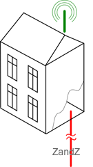 пis carried out as a calculation of an ordinary vertical ground conductor made of a metal rod 14.2 mm. in diameter.
The formula for calculating the resistance of a single vertical ground conductor:
where:
ρ – soil resistivity (Ohm *m)
L - length (m) of the ground conductor
d - diameter of the ground conductor (m)
T - digging in of the ground conductor (Distance from the ground to the middle of the conductor) (M)
π - mathematical constant Pi (3,141592)
ln - natural logarithm
For ZANDZ ready-made kits of modular grounding resistance calculation formula is simplified to the form:
for ZZ-000-015
for ZZ-000-030
where:
ρ – - soil resistivity (Ohm *m)
The following values are taken for calculation:
L = 15 (30) m
d = 0,014 m = 14 mm
T = 8 (15.5) meters: taking into account the penetration of the electrode at the depth of 0.5 meters
Calculation of electrolytic grounding
Calculation of electrolytic grounding (Ground resistance calculation) is carried out as calculation of an ordinary 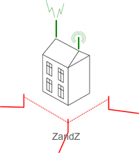 horizontal electrode in the form of a tube 2.4 meters long considering the impact of electrolyte on the surrounding soil (factor C).
The formula for calculating ground resistance of a single horizontal electrode with the addition of the correction index:
where:
ρ – soil resistivity (Ohm *m)
L Length of the ground conductor (m)
d diameter of the ground conductor (m)
T - penetration (distance from the ground to the ground electrode) (m)
π mathematical constant Pi (3,141592)
ln - natural logarithm
С – coefficient of the electrolyte content in the surrounding ground
Coefficient C varies from 0.5 to 0.05.
It decreases with time, because electrolyte penetrates into the soil to the greater volume, while increasing its concentration. As a rule, it is 0,125 after 6 months of the electrode salts leaching in dense ground and in 0.5 - 1 month of the electrode salts leaching in loose ground. The process can be accelerated by adding water to the electrode at the mounting.
For electrolytic grounding of ZANDZ , ground resistance calculation formula is simplified to the form:
- for ZZ-100-102
where:
ρ – resistivity of the soil (Ohm*m)
The following values are taken for the calculation:
L = 2,4 m
d = 0,065 m = 65 mm
T = 0,6 m
С = 0,125
Calculation of the grounding: practical data
It is worth paying attention to the fact that the results obtained almost ALWAYS differ from the theoretical calculations of the grounding.
In case of deep / modular grounding - The difference is connected to the fact that the calculation formula often uses UNCHANGED ESTIMATED soil resistivity ALONG THE WHOLE DEPTH of the electrode. Although in reality, this event is never observed.
Even if the nature of the soil does not change - its resistivity decreases with depth: the soil becomes denser, wetter; at the depth of 5 meters water layers are often met.
In fact, the resulting ground resistance will be lower than the estimated one in times (in 90% of cases the grounding resistance turns out to be 2-3 times weaker).
In case of electrolytic grounding - The difference is connected to the fact that the calculation formula uses the coefficient "C"taken into account as an averaged correction value that can't be described in the form of formulas and correspondences. It is determined on the basis of many characteristics of the ground (temperature, humidity, friability, diameter of particles, hygroscopicity, salt concentrations, etc.)
The leaching process is long and relatively constant. With time, the electrolyte concentration in the surrounding soil increases. The volume of the ground with the presence of electrolyte around the electrode also increases. In 3-5 years after the installation the resulting "effective" volume can be described by a three-meter radius around the electrode.
Because of this, the resistance of electrolytic grounding of ZANDZ significantly decreases with time. The measurements showed a dramatical decrease:
- 4 Ohm right after the installation
- 3 Ohm in 1 year
- 1.9 Ohm 4 years later
Calculation of grounding in the form of severalel ectrodes
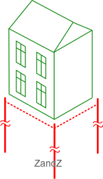 Calculation of grounding (ground resistance calculation) for multiple electrodes of modular grounding is carried out as the calculation of the parallelly connected single ground conductors
The calculation formula tconsidering mutual influence of the electrodes - use factor:
where:
R1 – resistance of singleground conductor / electrode (Ohm)
Ки – use factor
N – number of electrodes in the ground conductor
Contribution of the connecting ground conductor is not taken into account here.
Calculation of the required number of ground electrodes.
After the reverse calculation we get the formula for calculating the number of electrodes for the required value of the final resistance (R):
where:
] [ - rounding off the result to a greater value.
R – required resistance of a multi-electrode ground conductor (Ohm)
R1 – resistance of a single ground electrode / electrode (Ohm)
Ки – use factor
Contribution of the connecting ground conductor is not taken into account here.
The distance between the ground electrodes
In multi-electrode configuration of the ground conductor, another factor - distance between the ground electrodes- starts to put its impact.
In grounding calculation formulas, this factor is reported as the "use factor".
For modular and electrolytic grounding this factor can be ignored (ie, its value is equal to 1), subject to a certain distance between the ground electrodes:
- not less than the depth of immersion of the electrodes - for modular
- at least 7 meters - for electrolytic
Connection of electrodes to the ground conductor
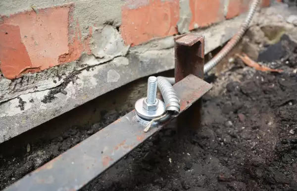
To connect the grounding electrodes to each other and to the object as a ground conductor,copper wire rod or the steel strip is used.
Conductor cross-section is often chosen of - 50 mm² for copper and 150 mm² for steel. Conventional steel strip 5 * 30 mm is often used.
For single-family houses without air terminals, copper wire with the cross-section of 16-25 mm² is enough..
For more details on the installation of the ground conductor see a individual page "Installation of grounding".
Сервис расчёта вероятности удара молнии в объект
Если помимо заземляющего устройства Вам предстоит установить систему внешней молниезащиты, Вы можете воспользоваться уникальным сервисом расчета вероятности удара молнии в объект, защищённый молниеприёмниками. Сервис разработан командой ZANDZ совместно с ОАО «Энергетический институт им.Г.М.Кржижановского» (ОАО «ЭНИН»)
Этот инструмент позволяет не просто проверить надёжность системы молниезащиты, но и выполнить наиболее рациональный и правильный проект защиты от молнии, обеспечивая:
- меньшую стоимость конструкции и монтажных работ, уменьшая ненужный запас и используя менее высокие, менее дорогие в монтаже, молниеприёмники;
- меньшее количество ударов молнии в систему, сокращая вторичные негативные последствия, что особенно важно на объектах со множеством электронных приборов (количество ударов молнии уменьшается с уменьшением высоты стержневых молниеприёмников).
Функционал сервиса позволяет рассчитать эффективность запланированной молниезащиты в виде понятных параметров:
- вероятность прорыва молнии в объекты системы (надёжность системы защиты определяется как 1 минус величина вероятности);
- число ударов молнии в систему в год;
- число прорывов молнии, минуя защиту, в год.
Имея подобную информацию, проектировщик может сравнить требования заказчика и нормативной документации с полученной надежностью и принять меры по изменению конструкции молниезащиты.
Для того, чтобы приступить к расчёту, перейдите по ссылке.
Related Articles:
 Why Cannot Vertical Earthing Devices Be Installed Close to Each Other?
 Electrolytic Grounding in Permafrost Soils: Should Vertical of Horizontal Electrodes Be Used?

