From the series of articles "Grounding in lightning protection - answers to frequently asked questions in the design".
Any horizontal grounding bus or a vertical electrode posess inductance. This means that the current does not instantaneously penetrate to the ground electrode, but actually loads its elements with a very specific speed. As a result, not the whole ground electrode system instantly switches into the process of rapidly growring lightning current. Its areas enter into operation gradually and the further is the specific site from the place of the surge current input, the later it enters into operation. In such circumstances, it is useless to focus on the measurements or calculation of grounding resistance for a direct (or rather - a slowly varying) current. The actual conditions of spreading of the lightning current can be incomparably worse and will be characterized by completely different, multiply increased grounding resistances. Pulse characteristics of grounding devices require an individual analysis.
When soil resistivity is not too large and active leakage current is considerably greater than the capacitive current from the surface of the bus, an LR-circuit with distributed parameters fits the descriptions of the spreading process (Fig. 24), which is described by the system of equations in partial derivatives.
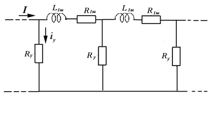
Figure 24
Their analysis shows that the current pulse edge distributes from the place of its input with the variable of decreasing speed over time, overcoming the distance in time t
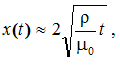
where μ0 = 4π10-7 H/m - vacuum permeability. The characteristic time of the lightning current pulse edge has the order of 1 microsecond, during which the pulse will move along the conductor to the distance of about 20 m if ρ ~ 100 ohm m. This means that in such a ground, the grounding resistance cannot be considered unchanged in time at the characteristic size of the ground electrode of 20 m or more. In high-resistivity soils the conditions are more favorable, since the rate of current diffusion is proportional to ρ1/2. Consideration of time duration of grounding resistance for a complex grounding contour configuration is a very difficult task, which is generally numerically solved with simplifications and greater expenditures of computer time.
The technical guidelinesdescribing pulse properties of the grounding device often use the concept of impulse grounding resistance. Conventionally, it is taken equal to the ratio of the maximum voltage value the ground electrode to the amplitude of the pulse current. The value has no physical sense, as the voltage and current peaks, usually do not coincide in time. It is suitable only for a qualitative comparison. The essential difference between the pulsed and the constant resistance values indicates the fact that the pulse mode of the ground electrode cannot be neglected. Under these conditions, a ratio of current values of voltage on the ground electrode and the loading of its current R3(t) = U3(t) / I (t) should be the characteristic of current spreading in the ground. By analogy with the existing terminology, such magnitude should be called an input impedance of the ground electrode system. Calculated data in fig. 25 show how strongly the value of R3(t) changes in time. Numerical simulation reproduces the work of the horizontal ground bus 200 m in length and 1 cm in radius. It is accepted that it is placed in the ground with a resistivity of 100 ohm m at a depth of 0.5 m, and in the steady state would provide grounding resistance of 1.2 ohms. We consider an idealized case of loading the current of unlimited duration with a rectangular pulse. In 1 ms the grounding resistance is 10 times above its stationary value, even after 10 ms after the input of the current into to the bus the difference is still threefold. The reason for the increased resistance to earth is slow penetration of the surge current into the bus.
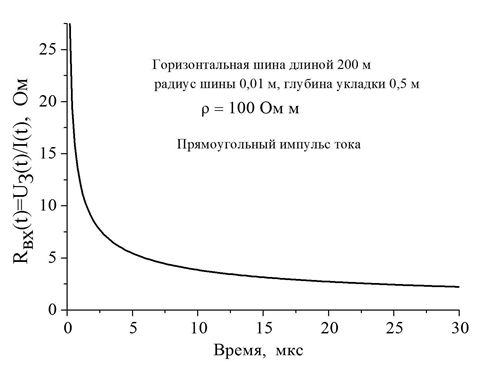
Figure 25
Горизонтальная шина длиной 200м - horizontal bus 200 m long
Радиус шины 0,01 - bud radius 0,01
Глубина укладки 0,5 м - burial depth 0,5m
Прямоугольный импульс тока - rectangular current impulse
Время, мкс – time , ms
In fig. 26, where the calculated values of the leakage current density from the bus surface to the ground, it is evident that at short time intervals, only the initial part of the bus operates actively. Even at 20 ms half of its length in the current spreading is only partially involved.
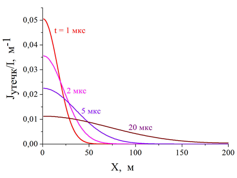
Figure 26
Время, мкс – time , ms
Such a significant response time is especially characteristic of highly conductive soils. With the increase in resistivity the delay of active work start becomes less important, in the result of which the grounding resistance rapidly approaches its stationary level (to be fair it should be noted - to the higher level in high resistivity soils). Results of numerical simulation in Fig. 27 show the time course of the process for a bus 100 m long at different values of soil resistivity. Quick stabilization of the grounding resistance value is typical for soil with the resistivity above 2000 ohm m. In the grounds of increased conductivity, the transitional regime takes more than 2 microseconds, which is quite comparable with the duration of the lightning current edge and that is why the dynamics of the grounding resistance change must be taken into account in the calculation of storm surges, step and touch voltage, practically linearly dependent on R3(t).
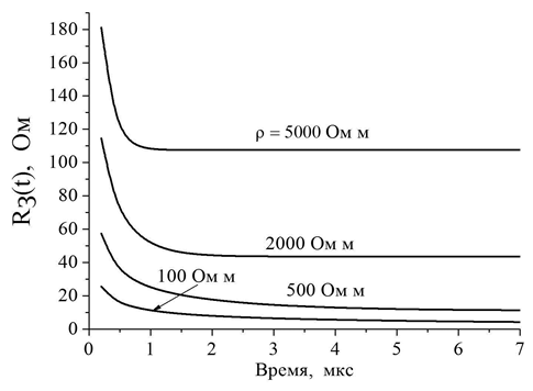
Figure 27
Время, мкс – time , ms
Ом м – Ohm m
A strong time dependence of the grounding resistance is typical for large area grounding contours. See an example of such a dependence in the result of the numerical simulation built in Fig. 28 for a square contour 200x200 m with cells 10x10 m.
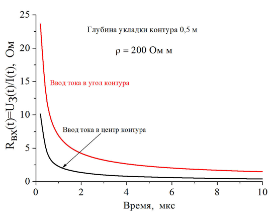
Figure 28
Глубина укладки контура 0,5 м – contour burial depth 0,5 m
Ввод тока в угол контура – current input into the corner of the contour
Ввод тока в центр контура – current input into the center of the contour
Время, мкс – time , ms
In soil with a resistivity of 200 ohm * m (typical value for the soils Russian midland) this circuit, lying at the depth of 0.5 m, would have the grounding resistance of about 0.45 ohms in a stationary mode. A simple comparison of this value and the grounding resistance in a pulse mode is impossible, because the latter essentially depends on the current input place into the grounding contour. The transition process takes the shortest time, when the current is introduced into the center of the contour (here the insertion point is equally distant from all symmetrically arranged grounding elements), the longest time - when entering it into one of its corners. For example, in 2 microseconds at the central current input the grounding resistance exceeds the stationary value in 3 times, whereas in case of input into the contour angle - in about 10 times; for time of 5 ms the corresponding values are equal to 1.45 and 5.1. This significant difference makes to treat calculations of the voltage on the grounding device and quantitative estimates of potential distribution within a grounding contour and its immediate surroundings with caution. Calculated dependence in Fig. 29 shows the dynamics of change in step voltage time in the center of the contour we've just studied. The range of values turned out to be so wide that a logarithmic scale was required for the diagram. Indeed, at the estimated lightning current of 100 kA, the initial step voltage exceeded 100 kV, in 2 ms it reduced to 10 kV and in 10 ms was only 2 kV.
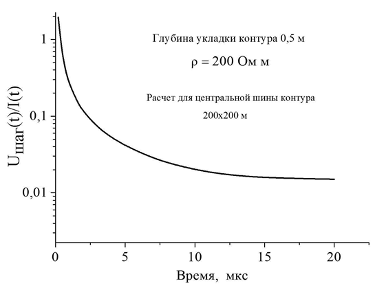
Figure 29
Глубина укладки контура 0,5 м – contour burial depth 0,5 m
Расчет для центральной шины контура – calculation for the central bus of the contour
Время, мкс – time, ms
The experts still don't have a significant idea about impact of the pulses of microsecond duration on humans and animals. As for microprocessor technology, the situation is quite definite here. Even nanosecond surges are enough for its irreparable damage.
You cannot ignore the question of the shape of the lightning current pulse. From what has been said in this section, it is clear that the most difficult task is to drain the impulse current with a sharp edge into the ground. At a small time of the current grwoth the grounding contour of any large size doesn't manage to get involved into operation - only the closest to the place of impact underground elements take active part in current spreading. As a result, the current value of the grounding resistance R3(t) appears to be strongly excessive. The voltage on the ground electrode U3(t) = R3(t) I (t), and step and touch voltage grow together with it. Here's how the voltage on the grounding contour 100x100 m with cells of 10x10 m at the depth of 0.7 m in a well conducting soil with ρ = 100 Ohm * m changes. Two current pulses with different edges are chosen. The first with the edge time tf ≈ 2 ms (Fig. 30) corresponds to the steepest for the first lightning component, the second, with tf ≈ 20 ms - the most flat (Fig. 31). 30 kA amplitude current (average value for the first component) was introduced into one of the corners of the square contour. The voltage was calculated at the point of entry and in the center of the contour.
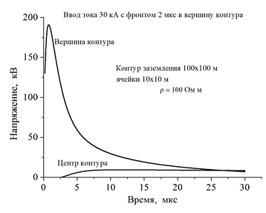
Figure 30
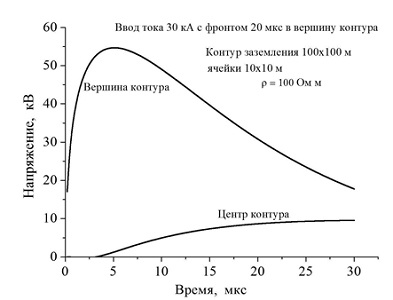
Figure 31
Напряжение, кВ- voltage, kV
Ввод тока 30 кА с фронтом 2 мкс в вершину контура- 30 kA current input with the edge of 2 ms to the contour top
Вершина контура – contour peak
Контур заземления – grounding contour
Ячейки- cells
Центр контура- contour center
Время, мкс –time, ms
Two fundamentally important points draw attention. Firstly, the bus contour in the pulsed mode are not under the same voltage. It is maximal at the point of the current input and it reaches a peak value much earlier than the current. With the distance from the current input location (eg, in the center of the contour) the voltage value drops down to the order of magnitude, and its growth to its peak value takes considerably longer time. Now imagine yourself underground utilities placed in the territory of the grounding contour. Its ends will appear under different stresses and the part of the pulse current, hardly desirable for the facility personnel, will go through the utilities.
Secondly, the peak value of the voltage in different places of the grounding contour is highly dependent on the current edge duration. It is most noticeable for contour parts, next to the site of the current input, where under the conditions considered, the edge reduction from 20 to 2 ms increased the voltage in almost 4 times. It is necessary to consider the overvoltage at the level of 200 kV for quite a moderate lightning current of 30 kA, even at very high-quality insulation of underground cables.
E. M. Bazelyan, DEA, professor
Energy Institute named after G.M. Krzyzanowski, Moscow
Read more "How to normalize the grounding resistance in lightning protection".
Useful materials:
- Series of articles about lightning protection for beginners
- Series of webinars about grounding and lightning protection with Professor E. M. Bazelyan
- Elements of external lightning protection
- Consultations on the selection, design and installation of grounding and lightning protection systems
Related Articles:
