Grounding resistance (resistance to electric current spreading) is defined as "countermeasures" to spreading of the electric current in the ground, coming to it through the ground electrode system.
It is measured in Ohms and must have a minimum low value. An ideal case - zero value, which means absence of any resistance at passing of "harmful" electric current, which ensures their FULL absorption by the ground.
Since it is impossible to achieve the ideal, all electrical equipment and electronics are made coming out of some normalized values of ground resistance = 60, 30, 15, 10, 8, 4, 2, 1 and 0.5 Ohms.
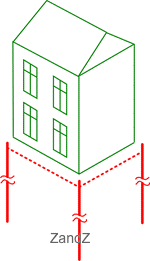
- for single family homes, connected to the electricity mains of 220 Volt / 380 Volt, you must have local grounding with the recommended resistance of not more than 30 Ohms.
When connecting the local grounding to the neutral of the transformer / generator, the total grounding resistance in TN system (local + all repeated + grounding of the transformer / generator) should be not more than 4 Ohms (EIC 1.7.101). This condition is fulfilled without any additional measures if a power source is properly grounded (transformer or generator)
Read more about this on page "House grounding".
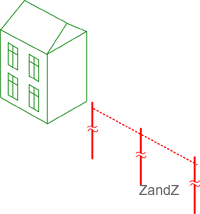
- connection of a pipeline to the house requires a standard requirement for house grounding. However, due to the use of dangerous equipment, it is necessary to carry out local grounding with the resistance of not more than 10 Ohms
(EIC 1.7.103; for all repeated groundings)
Read more about this on page "Grounding of gas boiler / gas pipeline".
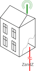
- for grounding used for connecting lightning rods, the grounding resistance should be not more than 10 ohms (RD 34.21.122-87, p. 8)
Read more about this on page "Lightning protection and grounding".
- for the power supply (generator or transformer), the grounding resistance should be not more than 2, 4 and 8 Ohms respectively, with linear voltages of 660, 380 and 220 V of a three-phase power supply, or 380, 220 and 127 V of a single-phase current source (EIC 1.7.101)
- for reliable operation of gas dischargers in protective devices of communication overhead lines (eg, local network based on copper cable or RF cable) grounding resistance to which they (dischargers) are connected should be not more than 2 Ohms. There are exemplars with the requirement of 4 Ohms.
- at the connection of telecommunications equipment, the grounding should generally have a resistance of not more than 2 or 4 ohms
- for 110 kV substation current spreading resistance should be not more than 0.5 Ohm (EIC 1.7.90)
The norms of grounding resistance given above are valid for soils with normal resistivity of not more than 100 Ohm · m (For example, clay / clay loam).
If the soil has a higher electrical resistivity - then often (but not always) the minimum value of grounding resistance increase to the amount of 0.01 of soil resistivity.
For example, in sandy soils with a resistivity of 500 ohm * m minimum resistance of house local grounding with TN-C-S system - increases 5 times - up to 150 Ohms (instead of 30 Ohm).
Calculation of grounding resistance
There are special formulas and techniques for calculation of grounding resistance, describing the dependence on the described factors. They are presented on page "Calculation of grounding".
Grounding quality
Grounding resistance is the main quality index of grounf electrode system and directly depends on:
- soil resistivity
- configuration of the ground electrode system. In particular: the area of electrical contact of grounding electrodes and soil
Soil resistivity
The parameter determines itself the level of soil "conductivity" as a ground conductor = how well the electric current, coming from the ground electrode system, will spread in such an environment. The lower this value is, the lower is the resistance of the ground.
Electrical resistivity of soil (Ohm * m) - is a measured value, depending on soil composition, size and density of its particles, its humidity and temperature, concentration of soluble chemicals in it (salt, acid and alkaline residuals).
Normally the table of approximate values "soil resistivity is used, "as its current measurement is only possible during special geological survey works.
Configuration of ground electrode system
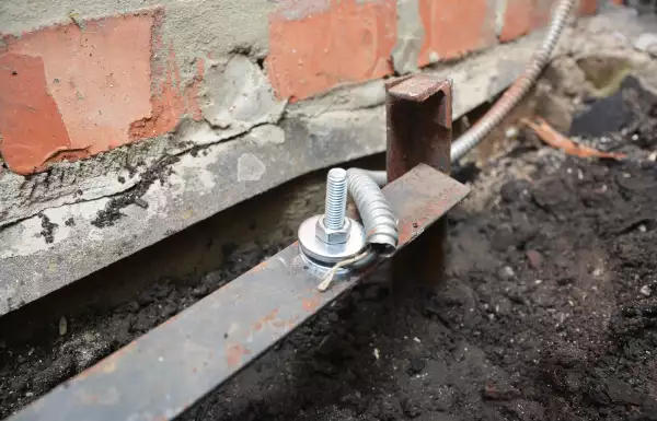
Grounding resistance directly depends on the area of electrical contact of the ground electrodes with the ground, which should be as large as possible. The greater is the surface area of the ground electrode, the lower is the resistance of the ground.
In most cases, due to easiness of installation, a vertical electrode in the form of a rod / tube / bracket is used as a ground electrode.
To increase the contact area of the ground electorde and soil:
- the length (depth) of the electrode is increased
- several short electrodes connected together placed at some distance from each other are used (grounding contour). In this case the areas of individual electrodes are simply added together, which is described in detail on an individual page about calculation of grounding.
Various industry standards
Grounding resistance for an urban telephone network cables with copper conductors (from Industry Standard 45.82-96, p. 8)
For metal screens and cable sheaths, the following values are taken (dependance on electrical soil resistivity):
| Resistivity, Ohm * m | <100 | > 100 <300 | > 300 <500 | > 500 <1000 | > 1000 |
| R, Ohm | 20 | 30 | 35 | 45 | 55 |
Related Articles:
 Why Cannot Vertical Earthing Devices Be Installed Close to Each Other?
 Electrolytic Grounding in Permafrost Soils: Should Vertical of Horizontal Electrodes Be Used?
 Protection of Fuel and Lubricant Materials (FLM) Storages with Floating Roofs Against the Static Electricity
 Five Most Dangerous Effects of Lightning