The 5th webinar about Surge Protection
Webinar text. Page 2
Quick slide navigation:
1. LEUTRON surge protectors
2. About Miroslaw Zielenkiewicz
3. SPD for low-current circuits
4. Guide for selection. Part 1
5. Guide for selection. Part 2
6. NAMUR standard
7. C-BUS standard
8. M-Bus standard
9. PROFIBUS and JohnsonControls
10. SIGMASYS standard
11. SUCONET standard
12. Series of MP arresters
13. Properties of MP series arresters
14. Installation of plug-in SPD modules
Page 2:
15. Generic terms of MP base
16. Connection diagrams of SPD
17. Engineering data of arresters
18. Base for security module "MP Base 1x2"
19. Base for MP Base 2x2 security module
20. Base for MP Base 2x2-R security module
21. Base for MP Base 2x2 GND security module
22. Base for MP Base 2x2-R GDT security module
23. SPD abbreviation expansion
24. Wiring diagrams of the elements
25. Dimensions of module
26. Components for MP and DataPro series
27. MP GDT ST arresters for primary protection
28. Wiring diagram of MP GDT ST
29. MP GDT Ad-Pg ST module
30. MP GDT Ad-Ad-Pg ST module
31. MP GDT 2x2 XX HF ST module
32. Series of MP RK narrow-body arresters
33. Engineering data of "MP RK GDT"
34. MP RK GDT Ad-Ad/Ad-Pg/Ad-Ad-Pg module
35. Wiring diagram of "MP RK GDT Ad-Ad/Ad-Pg/Ad-Ad-Pg"
36. MSR-M20 series of arresters
37. Protection of information and telecommunication systems
38. DataPro series of arresters
39. DataPro-1xRJ45-PoE-Alu SPD
40. Module of several SPDs
41. Surge protection with filters
42. Protection for radio
Generic terms of MP base
| MP – серия ограничителей перенапряжений для сигнальных линий со сменными модулями | MP - series of pluggable arresters for signal lines |
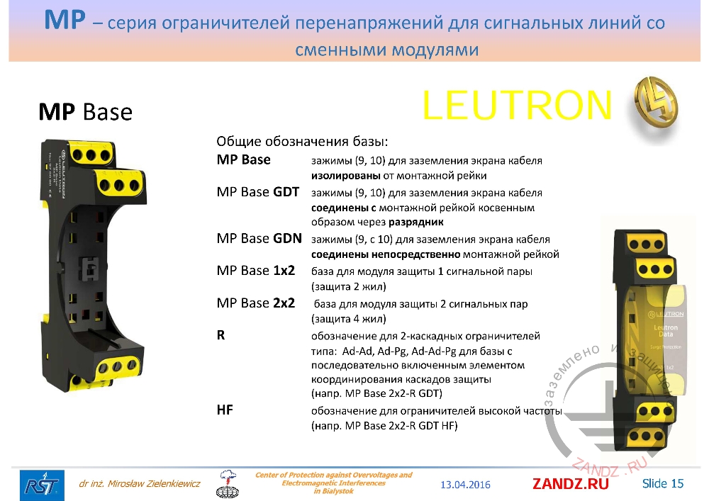
| Общие обозначения базы: | Generic terms of base: |
| зажимы (9, 10) для заземления экрана кабеля изолированы от монтажной рейки | (9, 10) terminals for grounding the cable screen are insulated from the mounting rail |
| зажимы (9, 10) для заземления экрана кабеля соединены с монтажной рейкой косвенным образом через разрядник | (9, 10) terminals for grounding the cable screen are connected to the mounting rail indirectly through a spark gap |
| зажимы (9, с 10) для заземления экрана кабеля соединены непосредственно монтажной рейкой | (9, с 10) terminals for grounding the cable screen are connected directly by the mounting rail |
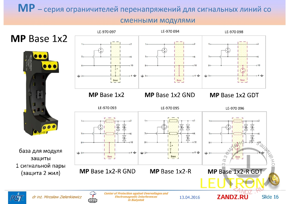
| база для модуля защиты 1 сигнальной пары (защита 2 жил) | base for the protection module of 1 signal pair (2 core protection) |
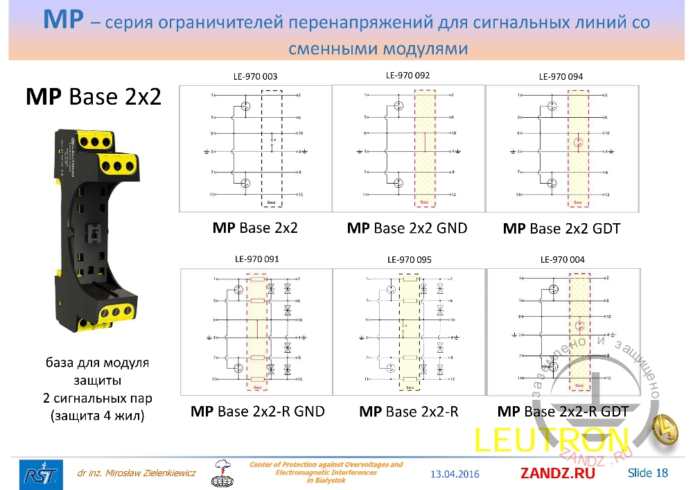
| база для модуля защиты 2 сигнальных пар (защита 4 жил) | base for the protection module of 2 signal pair (4 core protection) |
| обозначение для 2-каскадных ограничителей типа: Ad-Ad, Ad-Pg, Ad-Ad-Pg для базы с последовательно включенным элементом координирования каскадов защиты (напр. MP Base 2x2-R GDT) | designation for 2-cascade arresters of the type: Ad-Ad, Ad-Pg, Ad-Ad-Pg for a base with a series-connected element for coordinating protection cascades (eg MP Base 2x2-R GDT) |
| обозначение для ограничителей высокой частоты (напр. MP Base 2x2-R GDT HF) | designation for high-frequency arresters (eg MP Base 2x2-R GDT HF) |
— If we look at the base itself, the element of which is mounted on the DIN rail, we will see that there are many varieties. They are selected for different types of protection circuits that are placed in a pluggable module and for this we need to be able to connect them when we select them in the course of designing. That is, MP Base designation simply means base, “MP” is a series of arresters with pluggable modules. (9, 10) terminals that are listed here, are numbered on our base. They are used to ground the cable screen, and they are isolated from the mounting rail in this case. If this is our GDT designation, these terminals for grounding the cable screen are connected to the mounting rail indirectly through a spark gap. And if this base is GDN-labeled - (9, 10) clamps directly ground the cable screen to the mounting rail that must necessarily be connected to earth, but in practice it is the PE conductor in our facilities. MP Base 1x2 designation simply means that we are dealing with a protection module for one signal pair, that is, we are protecting only two cores.
Connection diagrams of SPD
— In order to understand this catalog - you will not find, so use this hint. You see different bases, different bases that are mounted on a DIN rail. If you look at the first diagram, we see that in this case we are dealing with insulating (9, 10) terminals, that are used to connect the screen from the grounding joint. But this T-4 joint connects directly to a DIN rail. In another case, when the GND designation, which we talked about, we are dealing with a direct shorting of this core with the (9, 10) clips on the (3, 4) grounded below. And in this case we are dealing with a spark gap connected between these two cores. What does it mean? This means that here we have cable screen insulation from the ground. In this case, the direct connection of the screen with the ground, and in this case we use a spark gap that will turn on only when we exceed its breakdown voltage. And at this time, when overvoltage is in this place, the spark gap will work for a short time, microsecond, will connect two cores of the screen with the ground. Remember that manufacturers of different systems do not always allow us to ground the end of the screen and then in this place it is recommended to use this option with a spark gap. In another case, when we deal with two-cascade circuits, we see that in the base there will be elements padding the first cascade with the second. And these elements are characterized by some kind of impedance, we will call it resistance. And for the same kinds of elements, we have the same two elements included in the lines, which coordinate us with two levels of protection, we talked about this in previous webinars.
Specifications of arresters
| база для модуля защиты 1 сигнальной пары (защита 2 жил) | base for the protection module of 1 signal pair (2 core protection) |
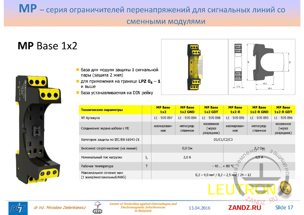
| для применения на границе LPZ 0B – 1 и выше | applicable at the boundaries LPZ 0B - 1 and higher |
| база устанавливаемая на DIN рейку | base mounted on DIN rail |
| Технические параметры | Specifications |
| № Артикула | Article No |
| Соединение экрана кабеля с PE | PE cable screen connection |
| Категория защиты по IEC/EN 61643-21 | Protection category according to IEC / EN 61643-21 |
| Вносимое сопротивление (на линию) | Insertion Resistance (per line) |
| Номинальный ток нагрузки | Load rated current |
| Рабочая температура | Operating temperature |
| Максимальное сечение жил (1 жила/многожильный/AWG) | Maximum section of cores (1 core / multi-core / AWG) |
| изолированное | insulated |
| непосредственное | direct |
| косвенное (через разрядник) | indirect (through the spark gap) |
— If we collect it in a table, then you will not find this table in the catalog. We see that for the base we use the protection module with one signal pair, the protection of two cores, as you have seen before. This base is applied on the boundary of LPZ 0B - 1 and higher zones, that is, the zone under the lightning protection system and the first, second, third internal zone - what comes to our mind during the designing. The dimensions of the elements are shown here, 17 mm is the width, the standard height is 68 mm.
— See slide 16. Such resistances, then they withstand a little less, that is, not so little - 4 times less.
— See slide 17. And we have a capacity of rated load current of only 0.5 A at that moment. This is very important if you have, for example, some kind of signaling device, you light it up, you have to look from the alarm system so that this current is exactly the maximum for this signaling device. If we look at the parameters by temperature, it can be seen that they can work in many climatic zones without problems. And what else is important for us in the design, which wires are connected. And we see that here I called, I have a little problem with the translation into Russian, it is a conductor with one core, the second conductor is multicore, when thin sections of cores, but the general section is indicated here. ABG is simply the American system for indicating signal standards.
Base for MP Base 1x2 security module
— If we look at the second base, which is already used for two signal pairs, then we protect 4 cores. So for them the designations are similar, as for signal ones, only here instead of the number 1 it has changed to the number 2. And we see that a PE conductor appears again. There is a cable screen and two signal lines that in this case are protected by a spark gap. Please look at this three-electrode arrester that protects, for example, 7, 8 conductor against the PE conductor of the screen. Depending on what we include here between the APE screen, we either insulate the screen or directly connect it, or connect it through a gas-filled arrester. So we get different ways to connect the screen. The most common method is a direct connection, that is the safest way, or an indirect connection through a cable screen discharger, then most of the energy goes to us immediately on the ground during an overvoltage. In the case when we have the letter R, there are elements that coordinate the second cascade with the first cascade. That is, we need to get a voltage drop on it so that with the sum of the voltage drop across the protective element would cause the arrester to work until our second stage is blown.

Base for MP Base 2x2 security module
— If we look at the table that is compiled of a two-signal pair of protection for four cores. The designations are similar, the connections are the same for the GND symbols without meaning and with the letter R, they are the same, the resistances are similar, here they are similar as in the previous case.
Base for MP Base 2x2-R security module
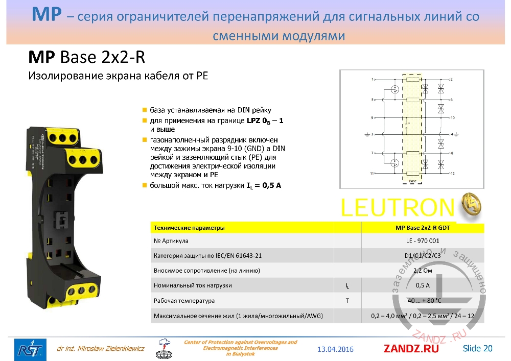
| Изолирование экрана кабеля от PE | Insulating cable screen from PE |
| база устанавливаемая на DIN рейку | base mounted on DIN rail |
| для применения на границе LPZ 0B – 1 и выше | applicable at the boundaries LPZ 0B - 1 and higher |
| газонаполненный разрядник включен между зажимы экрана 9-10 (GND) а DIN рейкой и заземляющий стык (PE) для достижения электрической изоляции между экраном и PE | gas-filled discharger is connected between the screen terminals 9-10 (GND) and DIN rail and grounding joint (PE) to achieve electrical insulation between the screen and PE |
| большой макс. ток нагрузки IL = 0,5 A | heavy maximum load current IL = 0.5 A |
— Let's see what kind of element that is isolated from the cable screen from the PE it is. As always, we mount all the elements on the DIN rail - this is the same for everyone of them. This spark gap is gas-filled, sorry, this is a mistake, we should have insulation here. Insulated, excuse me, please. And the load current, when selecting 0.5 A, we must take into account that in this case, when we select an element, we must understand which system of signal standards we have - symmetrical or asymmetrical.
Base for MP Base 2x2 GND security module
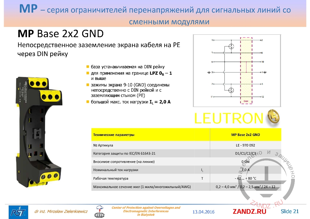
| Непосредственное заземление экрана кабеля на PE через DIN рейку | Direct grounding of cable screen to PE through DIN rail |
| база устанавливаемая на DIN рейку | base mounted on DIN rail |
| для применения на границе LPZ 0B – 1 и выше | applicable at the boundaries LPZ 0B - 1 and higher |
| зажимы экрана 9-10 (GND) соединены непосредственно с DIN рейкой и с заземляющим стыком (PE) | screen terminals 9-10 (GND) are connected directly to the DIN rail and to the grounding joint (PE) |
| большой макс. ток нагрузки IL = 2,0 A | heavy maximum load current IL = 2.0 A |
— The case when it is allowed to ground the screen, use the base with the GND designation. In this case, the terminals are connected directly to the DIN rail and the grounding joint, and all the energy passes from our first core to the ground in this way, and with the other core in the same way, through the short circuit of that core.
Base for MP Base 2x2-R GDT security module
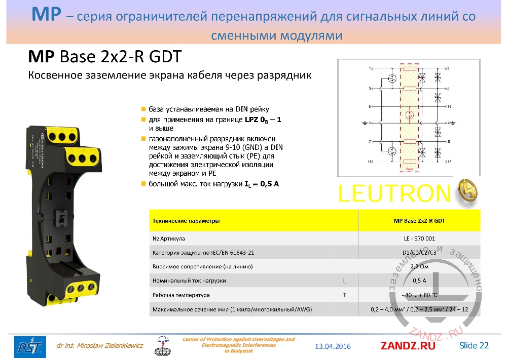
| Косвенное заземление экрана кабеля через разрядник | Indirect grounding of the cable screen through the spark gap |
| база устанавливаемая на DIN рейку | base mounted on DIN rail |
| для применения на границе LPZ 0B – 1 и выше | applicable at the boundaries LPZ 0B - 1 and higher |
| газонаполненный разрядник включен между зажимы экрана 9-10 (GND) а DIN рейкой и заземляющий стык (PE) для достижения электрической изоляции между экраном и PE | gas-filled discharger is connected between the screen terminals 9-10 (GND) and DIN rail and grounding joint (PE) to achieve electrical insulation between the screen and PE |
| большой макс. ток нагрузки IL = 2,0 A | heavy maximum load current IL = 2.0 A |
— In this case, when we have a cascade scheme and to coordinate this scheme in the base, we have placed the elements of coordination. And as we said, if they are in the base, we don’t pull them out when we change a module. In this case, they remain turned on all the time, then it is necessary until they fail, but this is a rare case. If we choose the electromagnetic environment correctly, we determine the equivalent environment for this place that we protect, so it will be very difficult to damage the base, but there are accidents. Then, in this case, we have a gas-filled spark gap connected between the screen terminals 9, 10, but the PE 4 conductor, that must be grounded, without this, our element will not be able to divert typical energy.
Abbreviation expansion of SPD
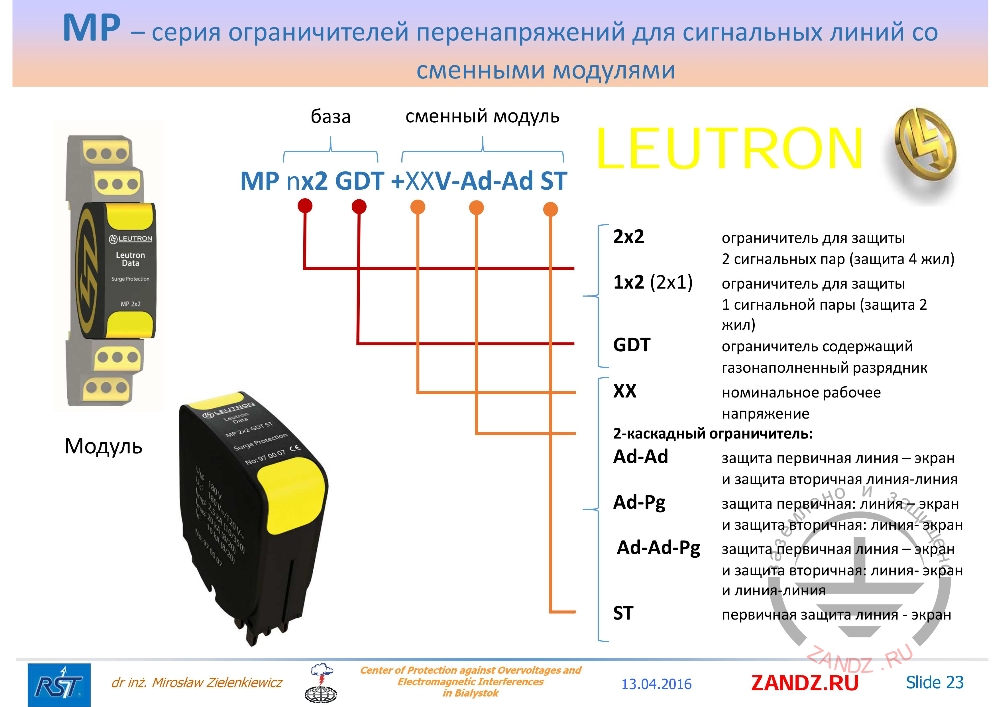
| база | base |
| сменный модуль | pluggable module |
| Модуль | Module |
| ограничитель для защиты 2 сигнальных пар (защита 4 жил) | arrester to protect 2 signal pairs (protection of 4 cores) |
| ограничитель для защиты 1 сигнальной пары (защита 2 жил) | arrester to protect 1 signal pair (protection of 2 cores) |
| ограничитель содержащий газонаполненный разрядник | arrester with gas-filled spark gap |
| номинальное рабочее напряжение | rated operating voltage |
| 2-каскадный ограничитель: | 2-cascade arrester: |
| защита первичная линия – экран и защита вторичная линия-линия | primary line protection - screen and secondary protection: line-line |
| защита первичная: линия – экран и защита вторичная: линия- экран | primary line protection - screen and secondary protection: line-screen |
| защита первичная линия – экран и защита вторичная: линия- экран и линия-линия | primary line protection - screen and secondary protection: line-screen and line-line |
| первичная защита линия - экран | primary protection: line-screen |
— In the names we see that in certain places there are certain designations. That is, the first designation MP is just a series with pluggable modules of arresters with surge arresters.
2x2 or 1x2 - mean either two signal or one signal pair. As a reminder, GDT in the base, this is the designation for the base, the designation is the arrester with the gas-filled spark gap. In this case, if there is no such designation, there is no spark gap. The next one is for the pluggable module. We have a rated operating voltage to make it easier to select an element. Then we have a two-cascade arrester called Ad-Ad - this means that we have a primary protection in such a pluggable module: line - screen, and the secondary protection is: line - line. The designation Ad-Pg is the primary protection: line - screen, and the secondary protection: line - screen. And the third case, when the designation Ad-Ad-Pg, we have the primary protection: line - screen, and the secondary protection: line - screen and line - line.
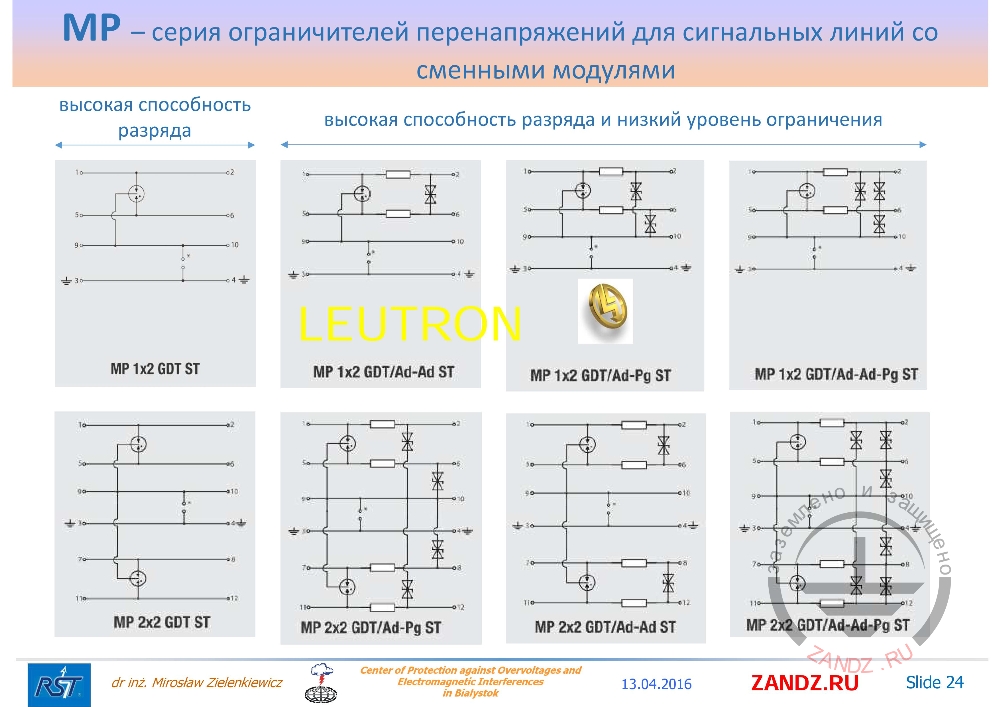
Wiring diagrams of the elements
| высокая способность разряда | high discharge capacity |
| высокая способность разряда и низкий уровень ограничения | high discharge capacity and low limit level |
— These designations - different triggering schemes, connection circuits of these elements appear. The schemes MP 1x2 GDT ST and MP 2x2 GDT ST as we see are similar, have a high discharge capacity, they pass a large current, a partial lightning current. Regular circuits, besides their high discharge capacity, are characterized by a low limit level about 10 V and more that means that this is a very accurate voltage system. In this case, if we look at the diagrams, we will see that everywhere they have a case of insulation in order to show that for this case we have a lot of different types of elements - it makes sense when we select this system.
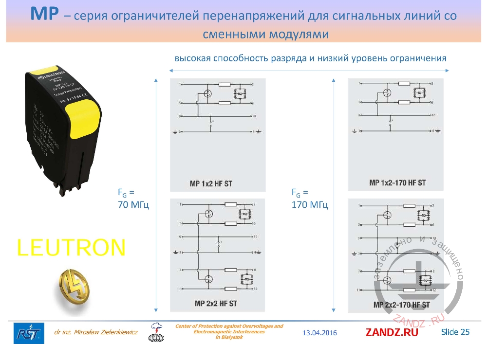
Dimensions of module
| высокая способность разряда и низкий уровень ограничения | high discharge capacity and low limit level |
— The module was chosen very carefully in terms of geometric dimensions, because during operation it is very important that it does not move and that the terminals do not short out under different conditions - this is also an important factor. In this case, if we look at the high-frequency elements, they are denoted by HF, then we see that the specially selected parameters of the diodes of the additional second cascade. They, as a rule, withstand low overvoltage energy and protect specially selected elements of the cascade, that is, inductance and resistance, and the arrester. The frequency of 70 or 170 MHz - this is also indicated in the designation of this element.
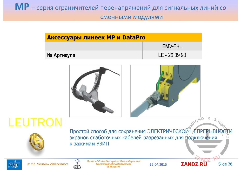
Components for MP and DataPro series
| Аксессуары линеек MP и DataPro | Components for MP and DataPro series |
| Простой способ для сохранения ЭЛЕКТРИЧЕСКОЙ НЕПРЕРЫВНОСТИ экранов слаботочных кабелей разрезанных для подключения к зажимам УЗИП | A simple way to save the ELECTRIC CONTINUITY of screens of low-current cables cut to be connected to the terminals of an SPD |
— All these elements can be connected using the geometrical parameters of the terminals. In such a simple way, the screen can be grounded and connected to the arrester depending on which base we use. But here you can see that the method is simple. For us, simply pull out a bigger screen and tie it up with a plastic clip. But it is necessary to remember that in conditions of high humidity such a solution is unacceptable, we need to insulate such places. If you use a box that has a good level of protection, a high EP - 65 - 66, this method may be sufficient.
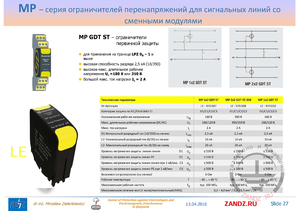
MP GDT ST - arresters for primary protection
| MP GDT ST – ограничители первичной защиты | MP GDT ST - arresters for primary protection |
| для применения на границе LPZ 0B – 1 и выше | applicable at the boundaries LPZ 0B - 1 and higher |
| высокая способность разряда 2,5 кА (10/350) | high discharge capacity 2.5 kA (10/350) |
| высокое макс. длительное рабочее напряжение Uc=180 В или 350 В | high maximum continuous operating voltage Uc = 180 or 350 V |
| большой макс. ток нагрузки IL = 2 A | heavy maximum load current IL = 2 A |
— If we look at the parameters, we recall the previous lesson, where we considered how to select parameters. Please remember that the first principle is not to damage the existing system, that is, not to suppress the signal. The question of what “not to suppress” is, I remind you, this means that we do not only conduct the attenuation of the signal, but it is important that we are always sure that this scheme will not change the functional properties of the system. For example, that the alarm indicator will trigger when necessary, and not because of the high current in the alarm device. The inductance connected in series into the line will burn out and the signaling device will not trigger - this protection is not needed by anyone, so you should always carefully select the parameters. What do we see? First, we must understand that this category of protection according to IEC / EN 61643-21, I showed you the table from which I followed in previous classes, we will see it below. Please see that for this D1 category of testing our element withstands the pulsed discharge current with a form of 10/350 μs. Remember that it is much more energetic than the impulse of 8/20 μs, because it is much longer. And in this case, all our elements withstand 2.5 kA partial lightning current. This means for us, for example, if you have the first category of protection, then we have to use such calculations, which are shown in the standards, to limit 100 kA, 40 such elements would have to be applied. But the question is: what is the point of applying 40 such elements? The way is different: we always count how many lines leave the object, if there are really 40 signal lines - this means that they are able to absorb such energy, it will divide into 40 of these signal lines and we will take it to the ground without any problems. But in this object there are always not only signal wires, but also power wires. Therefore, practice shows that due to the large cross section in the power supply cable and above them are large lightning currents, which are described in the formula 10/350 μs. Cases when the element is used to protect against induced currents, we see that in this case category C2 shows that our element is able to divert the nominal discharge current of 10 kA many times, and the maximum discharge current for such a circuit, that is, one-time 20 kA. This is a lot; it is a very energy-intensive element.
— Please look at the level of protection, very high. Protection voltage level: line - line, PE line - 550 V. Why so high? Because we use a gas-filled spark gap. The gas-filled spark gap has a greater surge voltage. 1 kV / µs - this is the rise time of the pulse front that gives us, usually, a couple of hundred volts of operation voltage of the element. This means that such an element does not have to protect microprocessor-sensitive circuits, where the voltage is 5 V. Therefore, such element is suitable only as a primary protection of a cable installed, for example, at the cable entry to a building, somewhere inside the object, we mount regular protection cascades, being part of this large set, which I now stipulate and considering that nominal currents (the maximum load current is indicated here) can flow along all the signal lines to our sensor or to the central control desk.
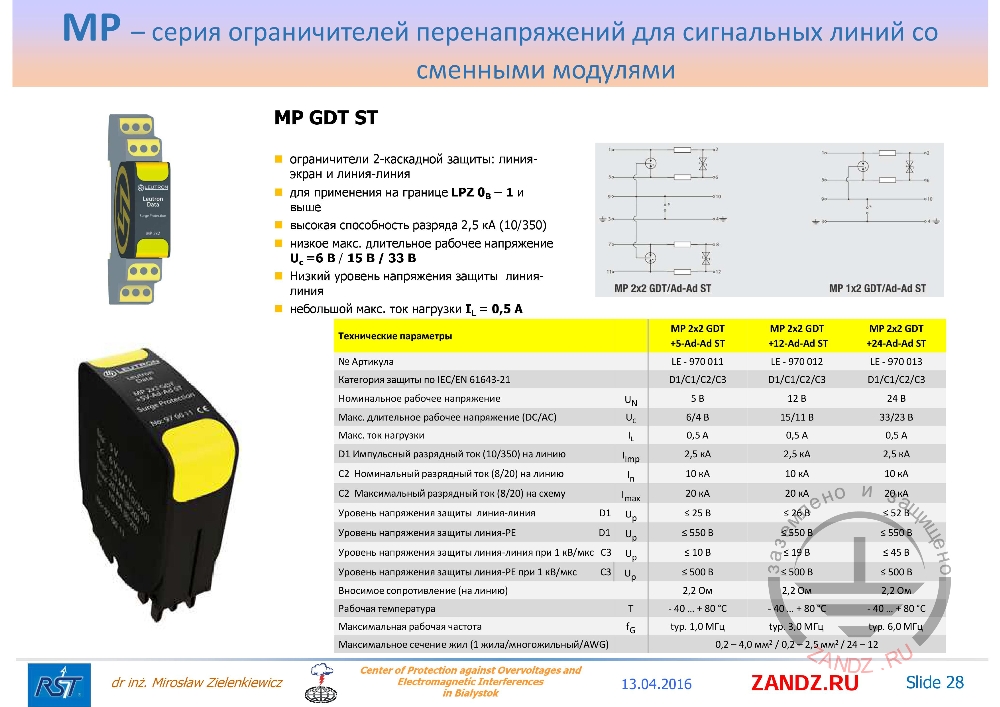
Wiring diagram of MP GDT ST
— Another difference in practice is the method of wiring. We see here that decoupling, insulating an element from PE means that the element itself in a given place must have an ability to absorb such energy. If our PE is connected, we don’t need it here, it will not help, because we have everything insulated. The nominal voltages are very low for this element, because the second cascade has appeared, and it determines the nominal voltage that is visible in the next elements. They appear in the name of the element as 5, 12, 24 V. And at that moment, the output voltage in the cascade between the lines also changes. We see that the diode is connected between two lines, and the spark gap is connected between the line and the ground. This is of great importance to us; this line is also protected by the same spark gap. Since we have two lines, similarly connected. For us, the situation in this module is clear.
<< Previous page
slides from 1 to 14
Next page >>
slides from 29 to 42
Useful materials for designers:
- Webinars with leading industry experts
- Everything for calculations of grounding and lightning protection
- Useful materials: articles, recommendations, examples
Related Articles:
