The fourth webinar of the series "BIM Design: From Fundamentals to Practice"
Webinar text. Page 2
Walls
|
Стены |
Walls |
|
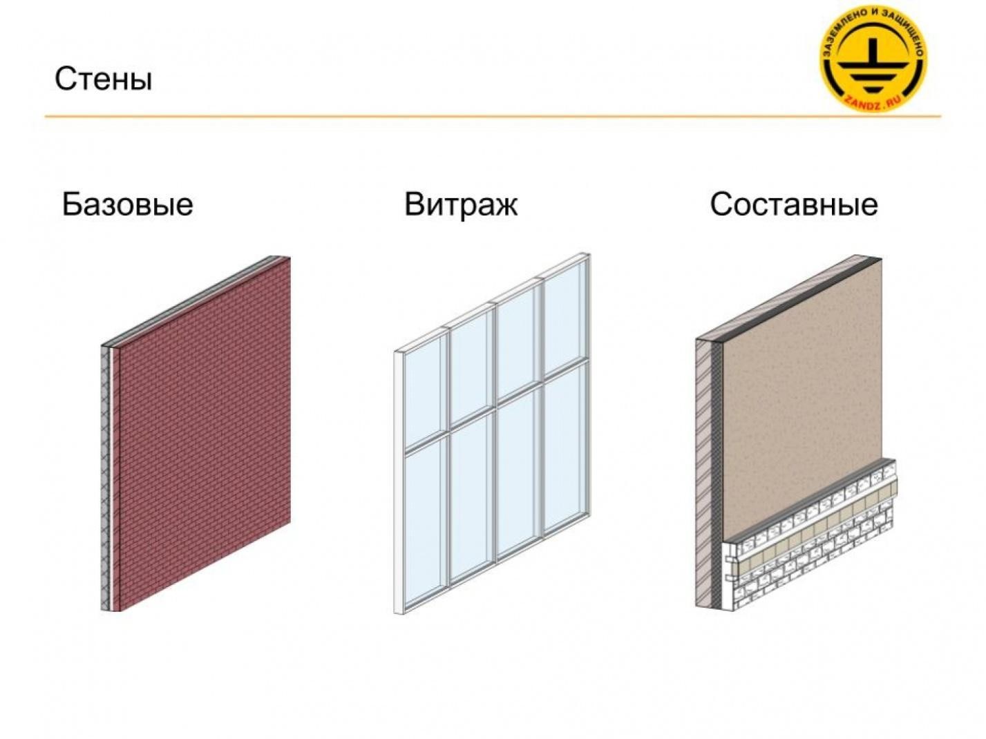
Базовые |
Base |
|
Витраж |
Curtain wall |
|
Составные |
Composite |
– In addition to the fact that the walls are classified into architectural and bearing or structural, they are also classified into the so-called subcategories. This is particularly true with regards to the architectural walls. We have basic walls, stained glass units and composite walls; these are the three wall categories. The basic walls are a multi-layered structure that consists of either one or several layers. A particular material, a particular thickness, and a particular function are assigned to each layer. For example, the function may be as follows: this layer may be bearing or heat-insulating, or simply insulating, or it can be a finishing layer. All of this can be defined. We will study it later. We have a subcategory such as curtain walls. The curtain walls are represented a little bit differently. We can see here that this system is composed of vertical and horizontal elements and is filled with such panels. The panels may be either glass or solid panels. We will also study this. And the composite walls; they consist of several basic walls divided horizontally. Here, we can see that, in this example, we have a finishing at the bottom of the composite wall, which is made of concrete blocks, and there is a wall made of plaster on the top. These are two different walls joined to obtain a single wall.
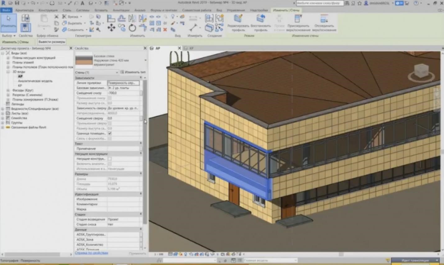
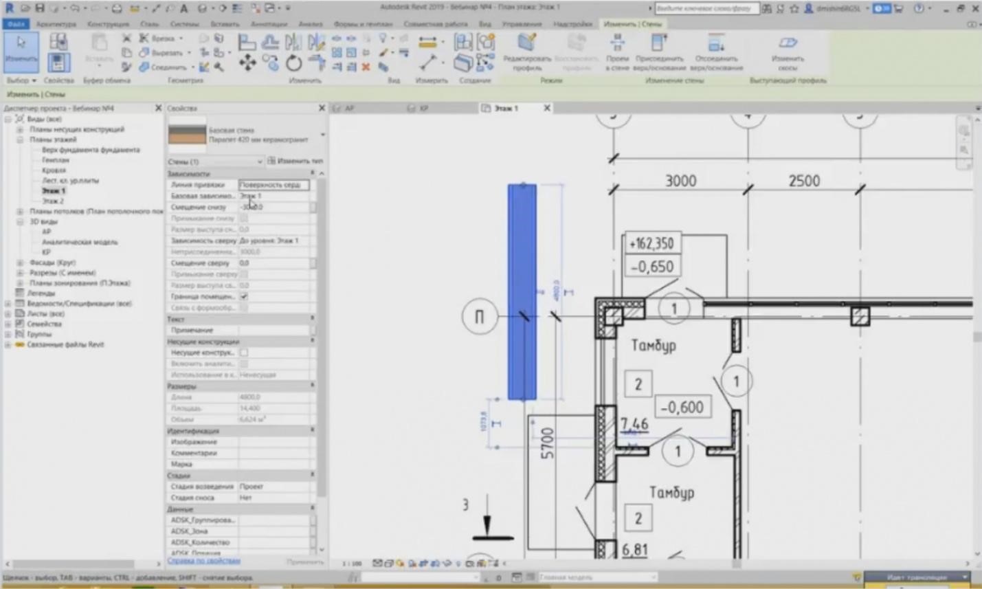
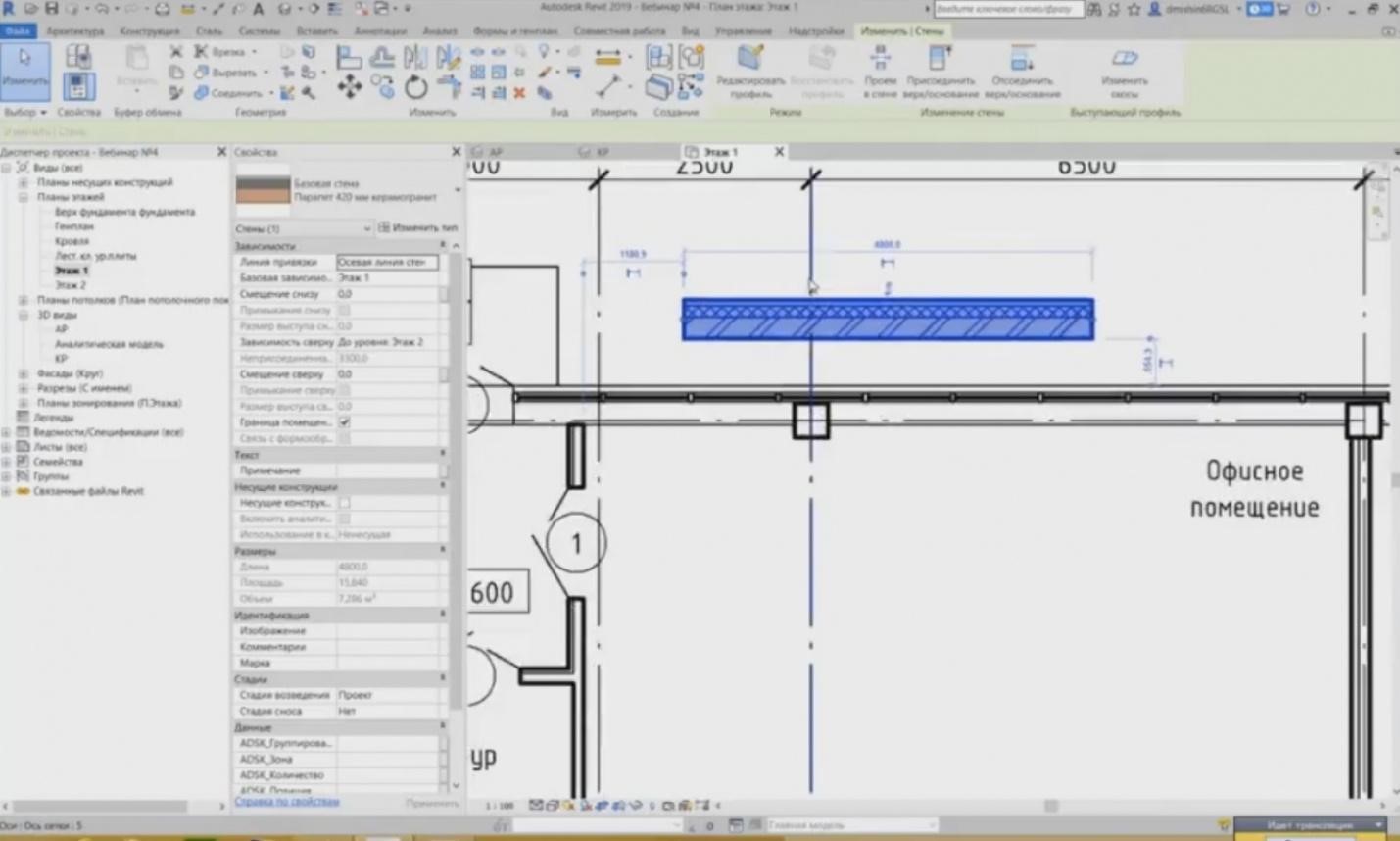
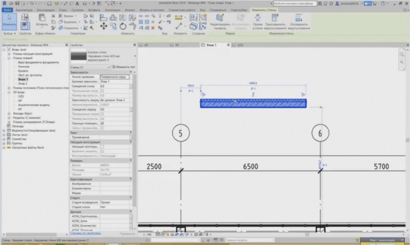
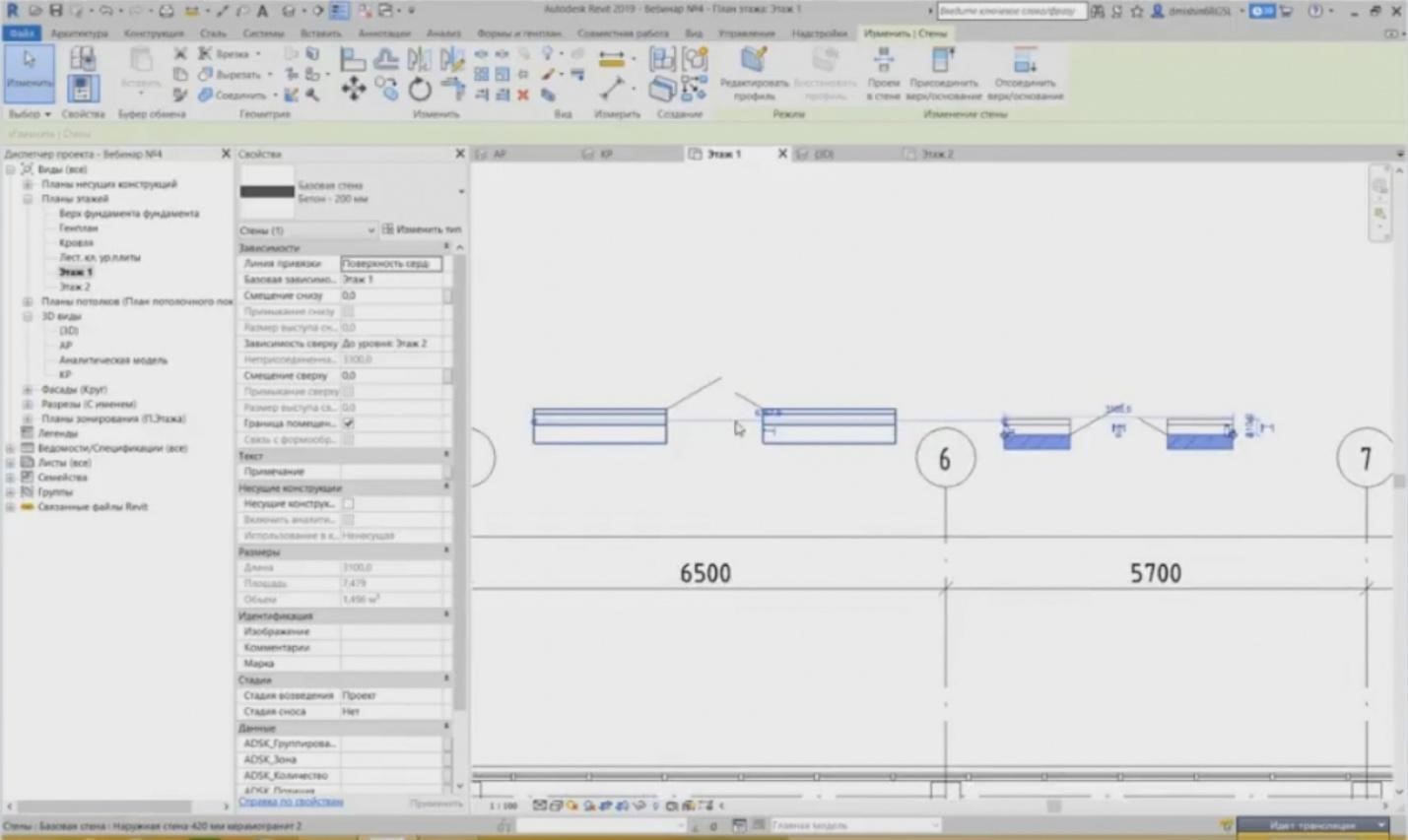
– Let's get back to our file. Let's look at what we have. If we choose a wall, then we will see, just like for other elements in the “Properties” window, the properties of the instance of this wall. We remember from the previous webinars that all of our elements have instance properties and type properties. The instance properties define the spatial position of our object, i.e. our wall. On what level it is located, what bottom or top offset it has, what is its height, is it a bearing wall? Moreover, we can see its dimensions here: the length, the area, and the volume of the wall. And various parameters: attributive, text that may be entered. This is, e.g., the wall position, the fire safety limit of this wall, a comment, or you can even add the text specifying on what floor it is located, etc. Any wall is created on the basis of a level. If we need to create a wall on the first floor, then we need the level of the first floor.
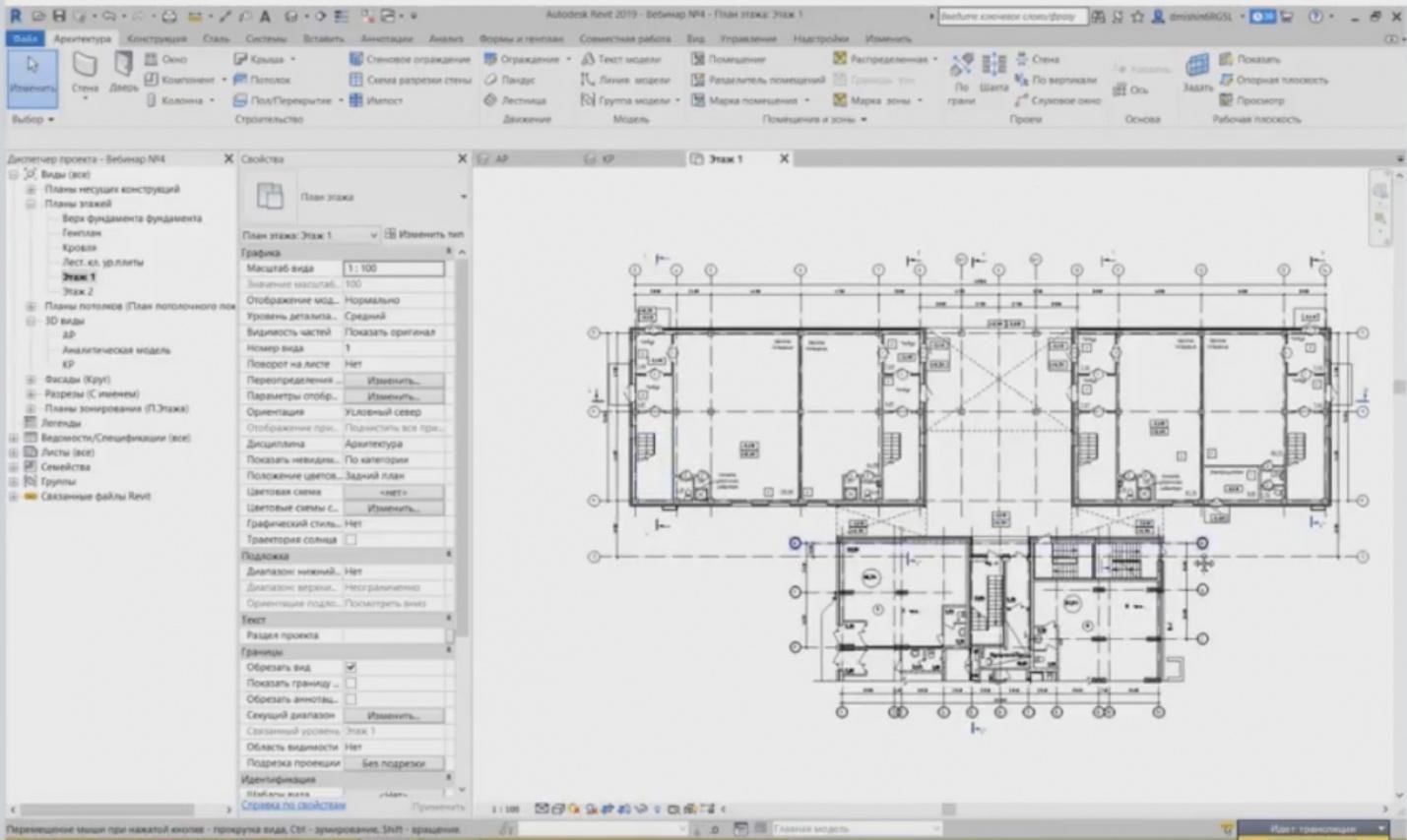
– I can go to the first floor plan for convenience. Here, we have the designed plan with marks, dimensions, and axes.
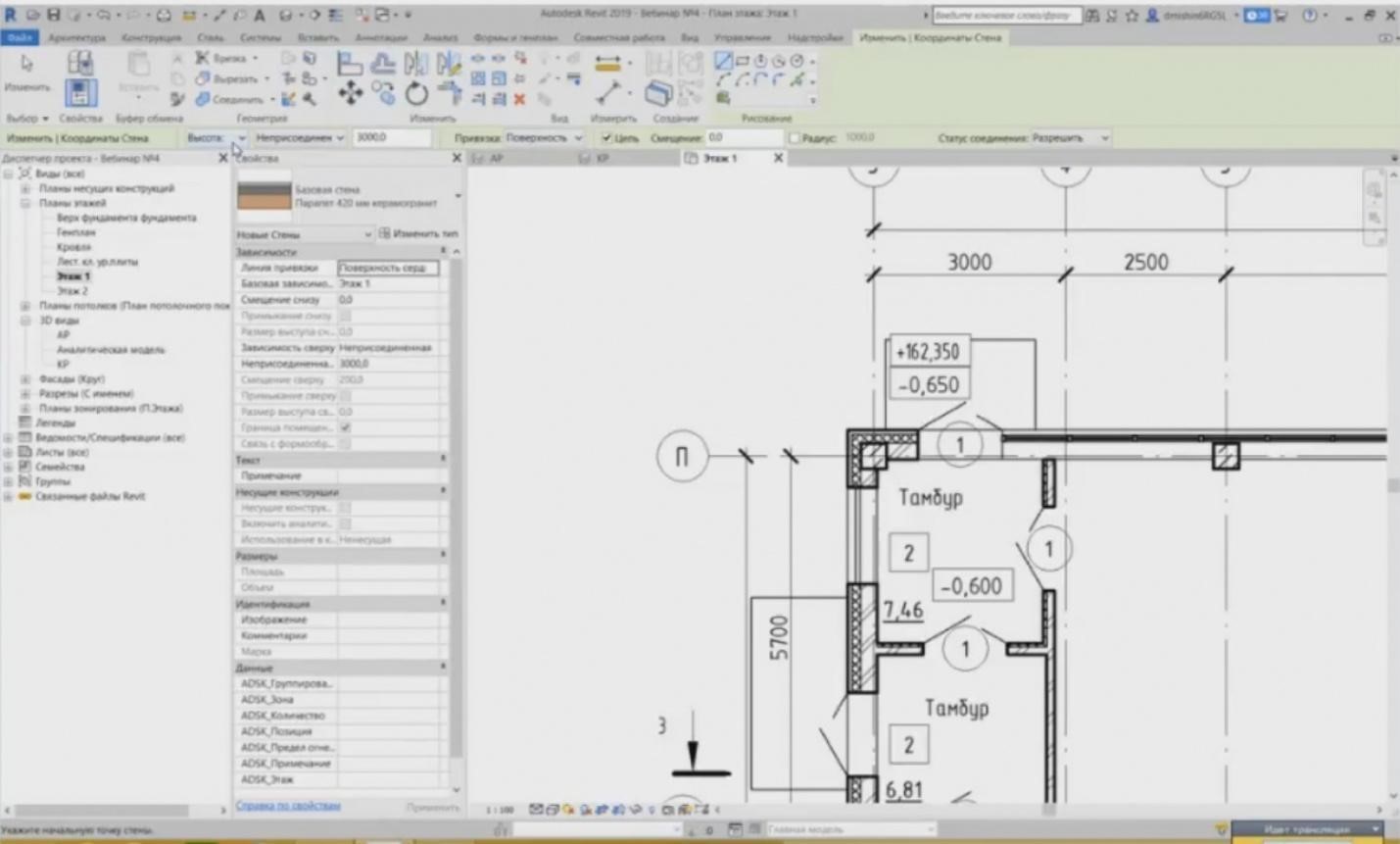
– Let's draw the wall. And the first thing we can see here is the top parameters that should be set. The first parameter is the height or depth. Where will a wall be created: should it be top or bottom relative to the level? The depth, i.e. that it will be created from top to down.
– It happens that when you set the depth, the wall is not shown. Although it is shown here for some reason. And you can see that it was projected from top to bottom to minus three meters relative to the first floor. It seems to be located behind it. So, if we choose the height, it will be created from bottom to top relative to the first floor up to the second floor.
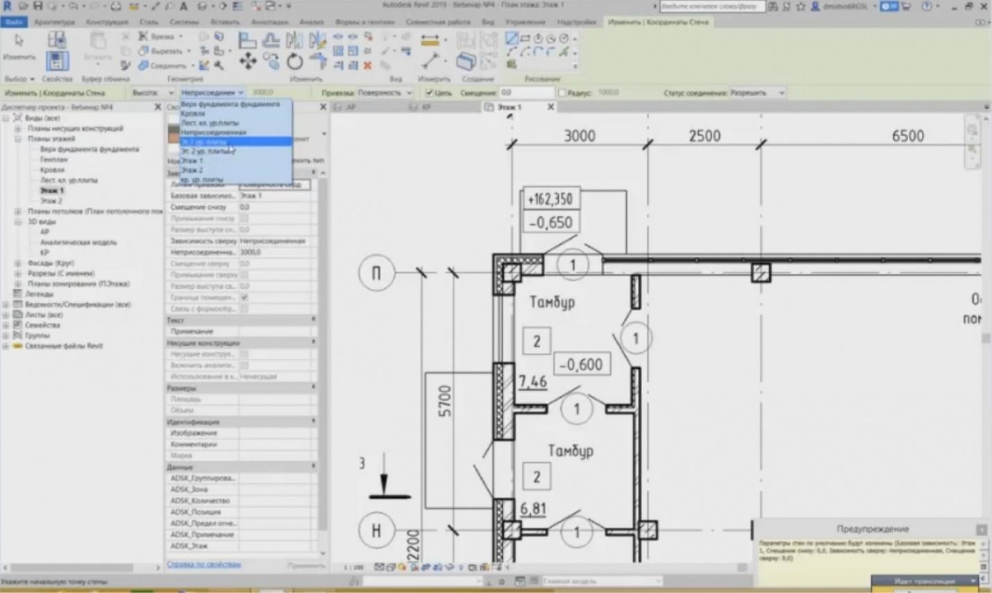
– Then, we choose the level to which we will draw the wall. This may be the level, e.g., of the second floor, or here also the levels of the floor panel of the first and second floors are present. We can also set the non-attached height. What is the difference between them? Why attach and why not attach? In what cases? In the cases when you have an interfloor wall, i.e. the wall between the floors, then it is certainly better to attach the wall to the upper floor. And when you change the levels in your project, e.g., when you have raised the level, made the floor height 3.3 meters instead of 3 meters, then all of these walls that are attached to the upper floor, they will also change their heights, as they are related to these levels. If you have a “non-attached” value, then no such thing happens. If you move the level, then the top part of this wall will remain at the same mark. Why do we need it? For example, for the walls such as a rampart, for which you define a particular value and you do not need to change it anymore. For example, you have set it at 1.2 meters. You do not have to change it relative to the levels. You have set 1.2 meters and it will not change any more.
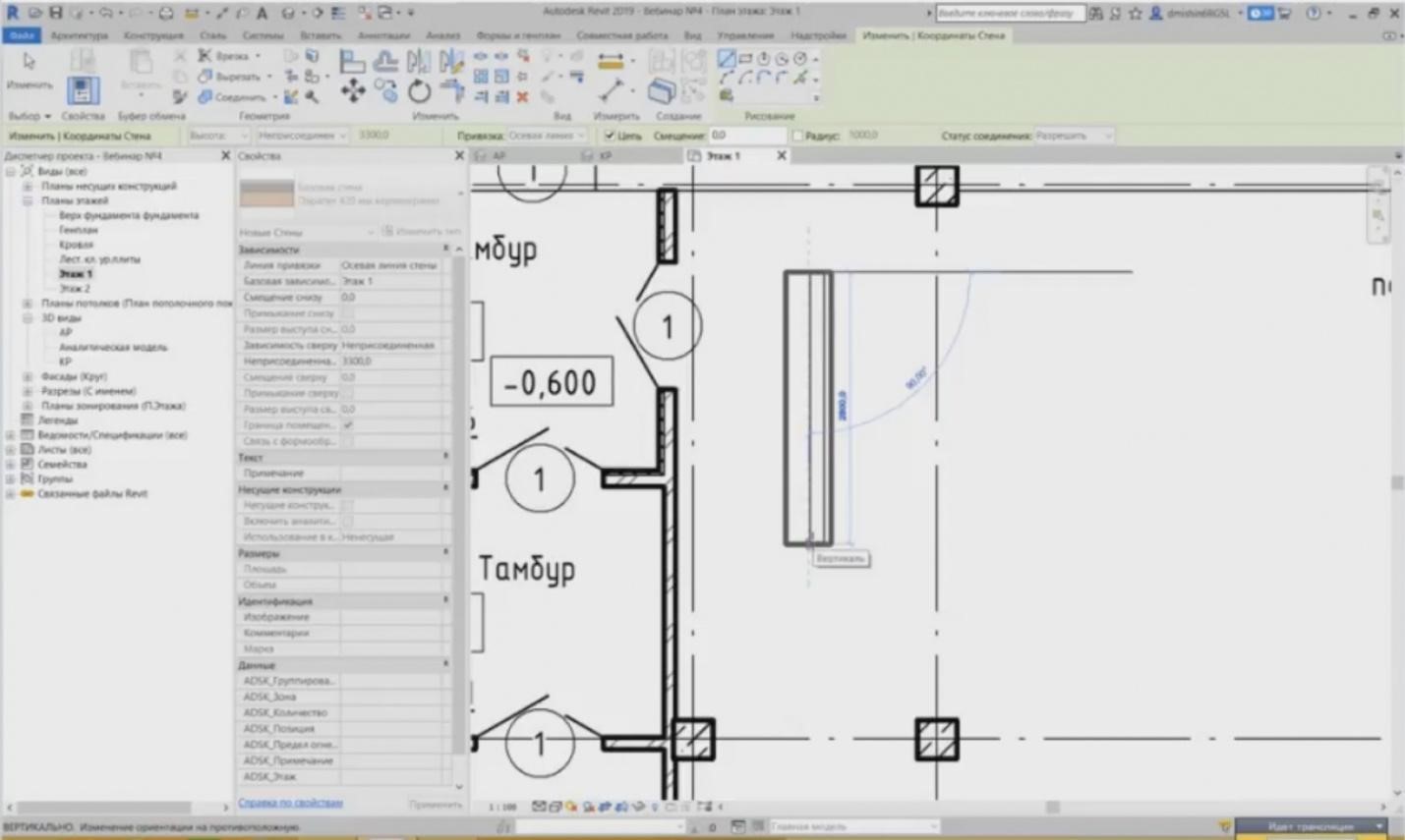
- Let’s go on. The walls have a so-called wall tie. The wall tie is responsible for the wall arrangement relative to the drawing line. If you take a look at any wall; when I create, then you can see that upon changing the tie, the wall position changes during its arrangement. I have an axis line of the wall here. My wall is located directly in the center relative to the drawing line.
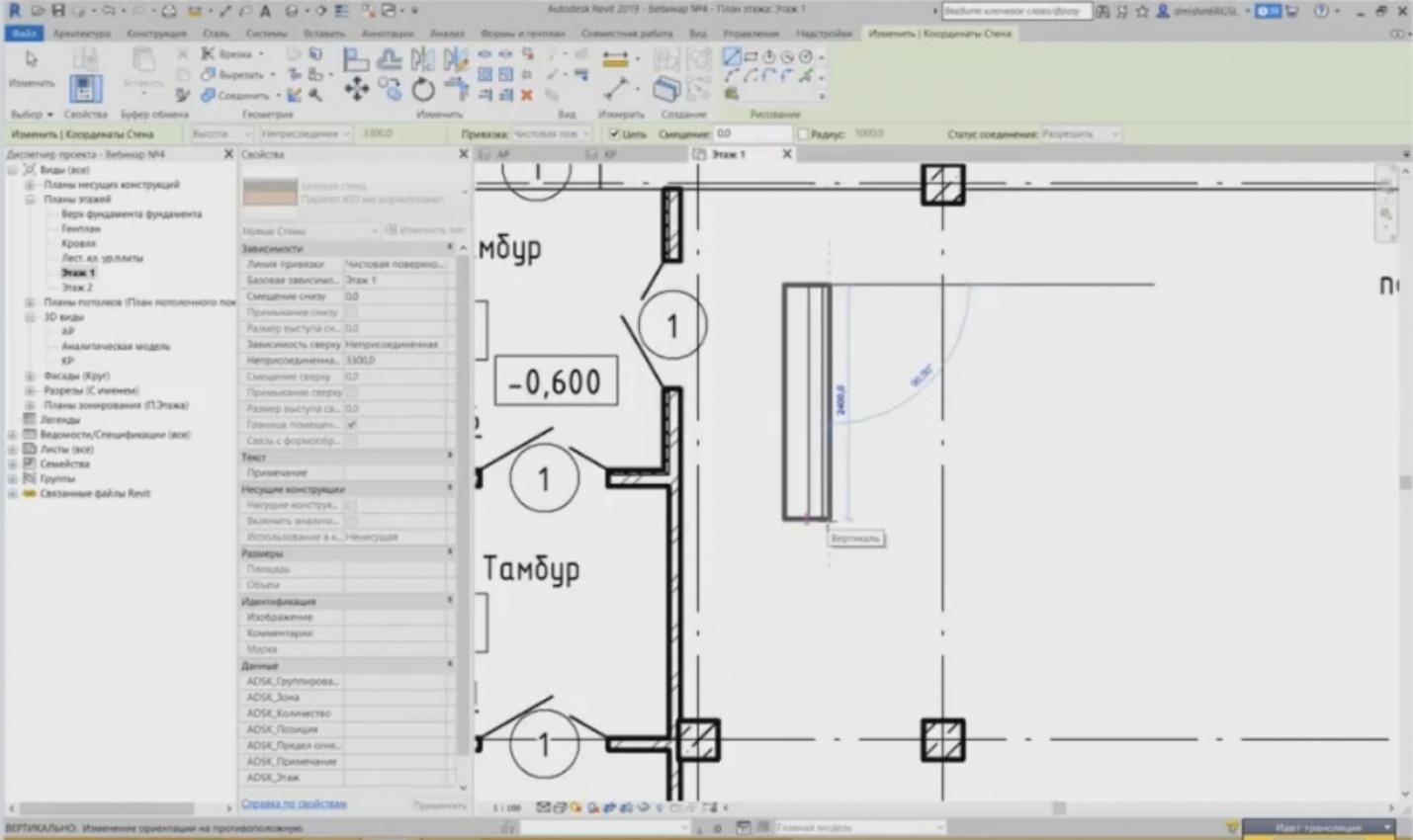
– If I choose “Clean Surface. External”, you can see that my wall is drawn externally relative to the surface.
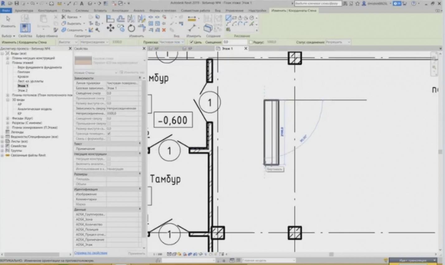
– And, respectively, the same is true for “Clean Surface. Internal”. It will be drawn internally.
– If you have started drawing a wall, and it is not located on the right side relative to the drawing line, you have to draw it downward, then you simply press a space button, and it will change the direction and will be drawn downward. This is very convenient.
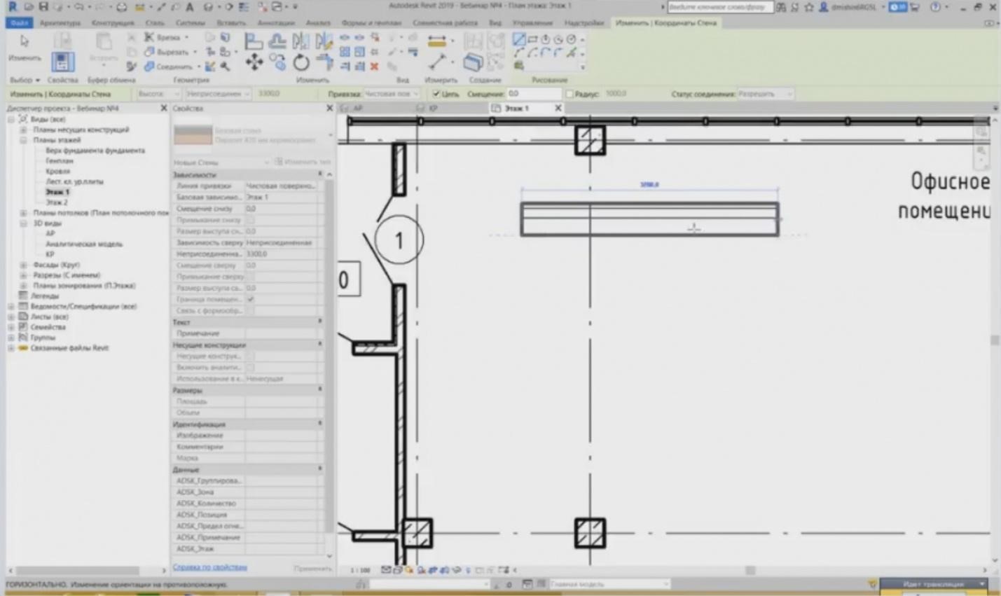
– Then, after setting these parameters, you may set the connection status. All walls in Revit are created with connections. If you draw two adjacent walls (this way), then an angle will be formed automatically to combine similar layers.
– If this button is disabled, then no connections will be made.
– After you have drawn several walls, let's see what we can do next. We have drawn a wall, and what can we see? When we highlight this wall, a button “Flip Wall Orientation” appears. The button is responsible for arranging an external surface. So, you should also control this so that all external surfaces would be arranged externally rather than internally. And to flip this wall orientation, you have to simply press the triangle, and the wall will flip relative to its axis. Or you press a space button as I have mentioned previously.
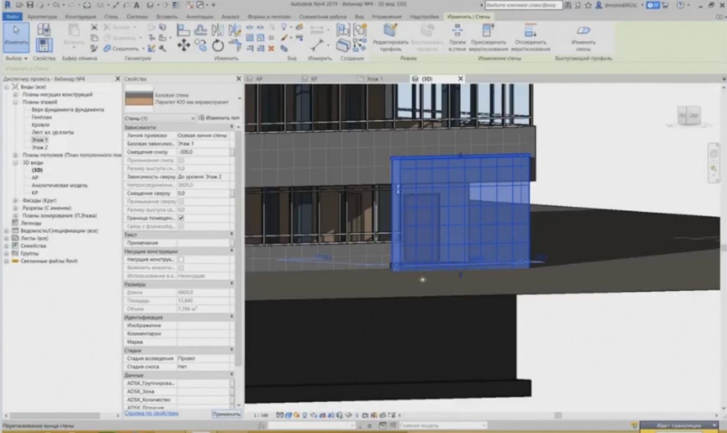
– If you need to raise or lower a wall to a particular height relative to the level, then you do not need to create a level at this mark; we have special parameters for that. Now, let's go to the 3D view. This is the wall I have created. Thus, if I need to lower it for a small height, I just need to determine the offset from the bottom for some height, e.g., 300 mm. And it is lowered. In this case, the relation to the level is kept; it has remained “Floor 1”. Positive and negative values work similarly as well as the offset from the top.
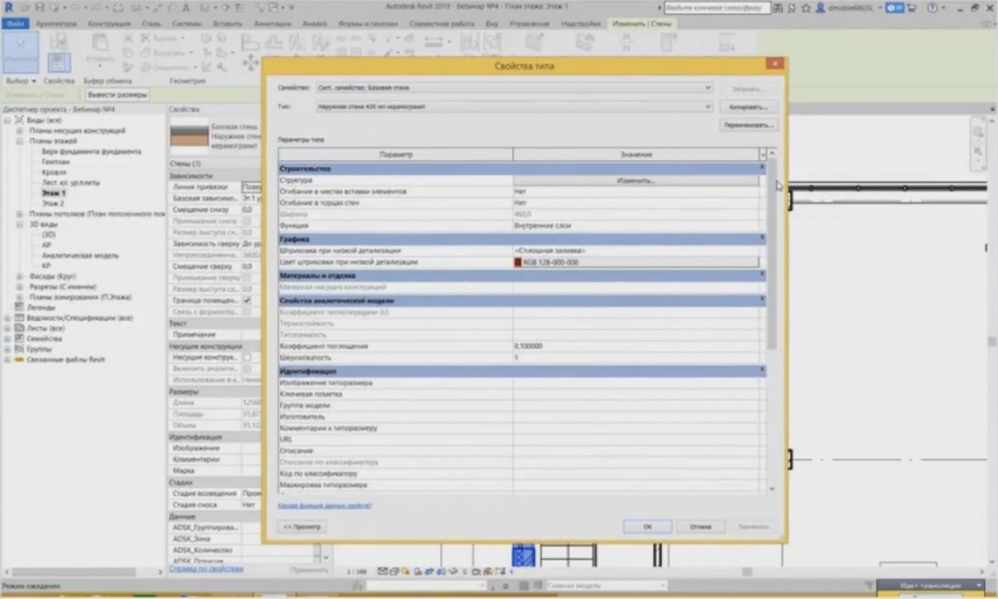
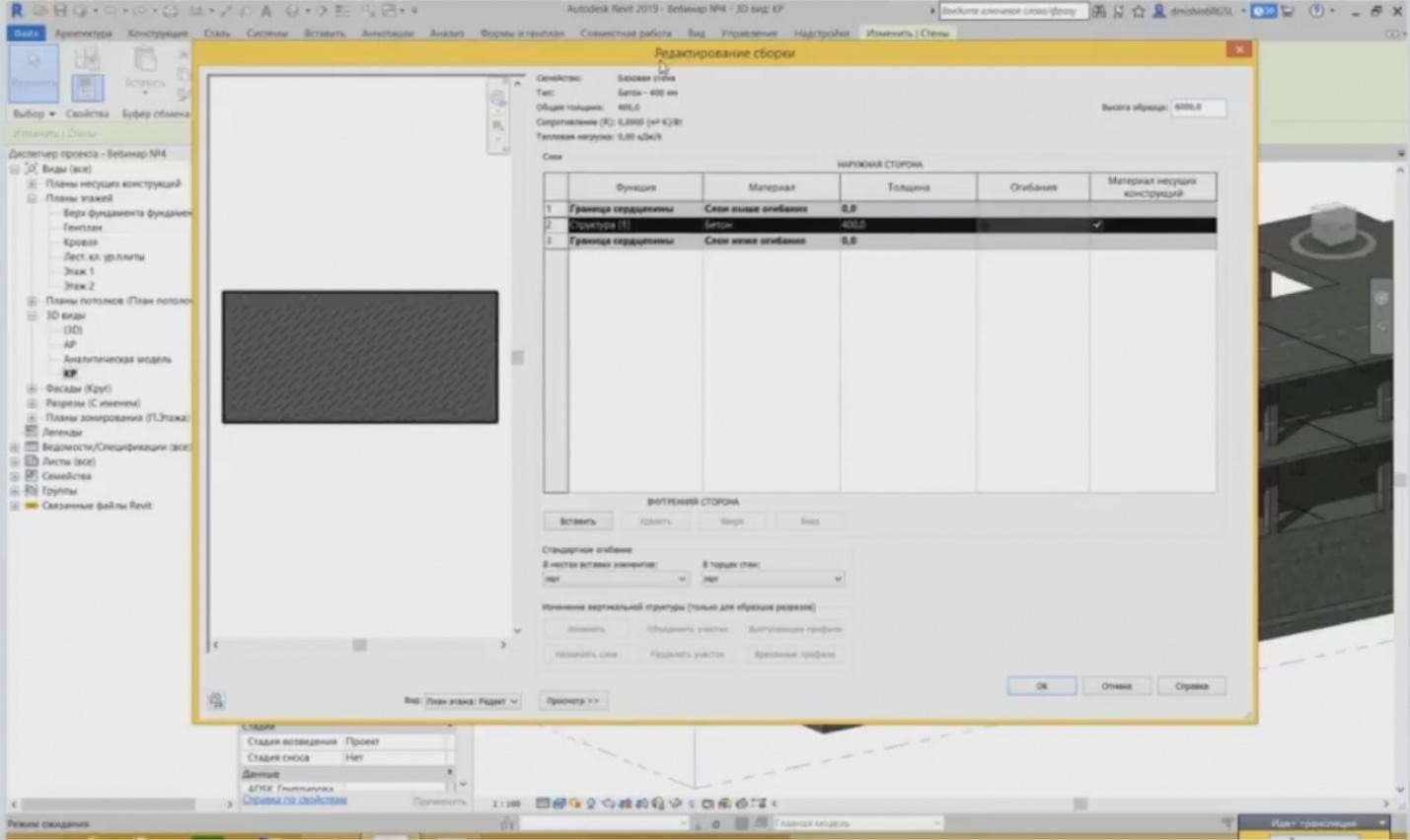
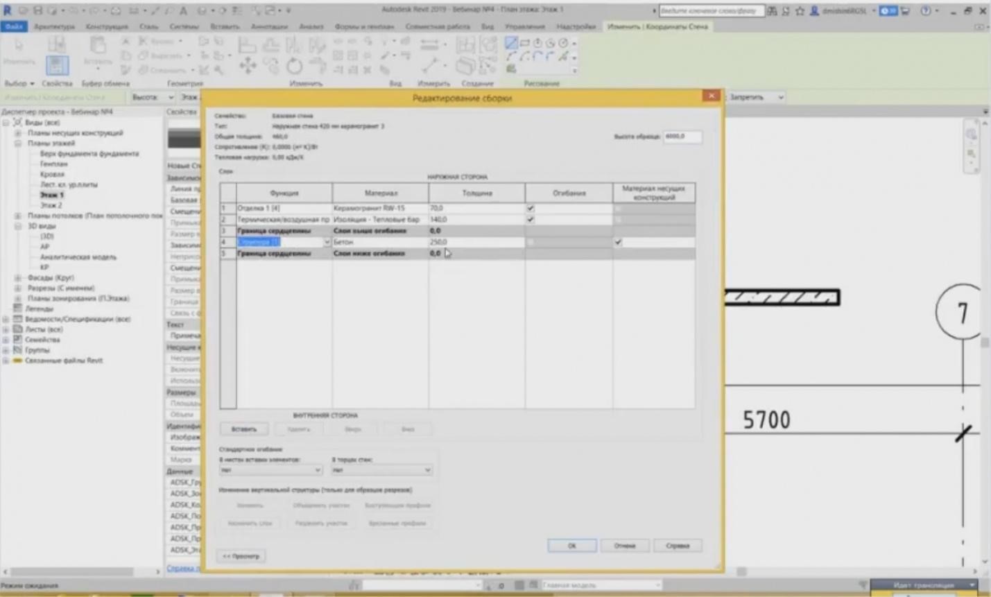
– Let's have a look at the type parameters of this wall. What do we have inside the type? Let's highlight the existing wall and press the “Change Type” button. Here, we have a parameter set; there are many parameters. Some parameters are system, while others are the parameters of the project to be added. I will tell you right away that all the parameters starting with words “ADSK” are common parameters created by the Autodesk Community. They are used in many design organizations. They have been created to provide a common base for all organizations working in Revit. What critical parameters do we have? The first parameter is the structure. We cannot set this parameter as a value. We can change it.
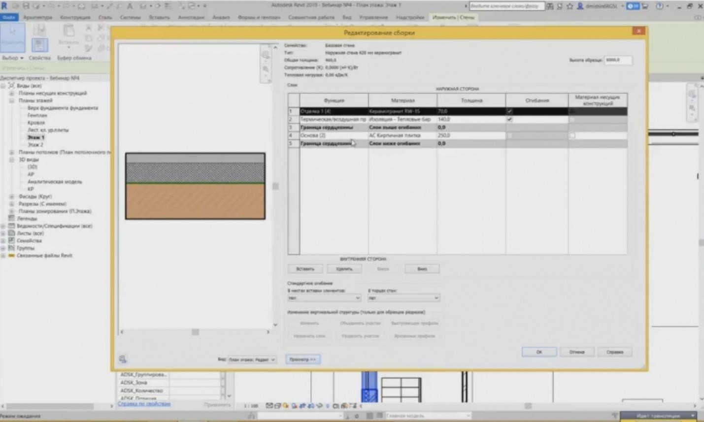
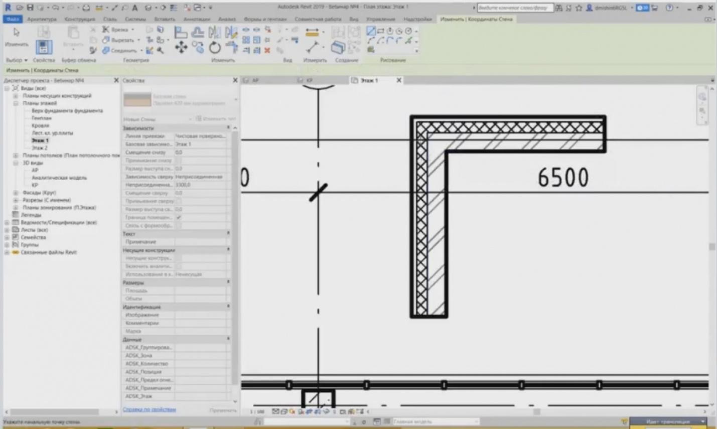
– And this parameter also contains a table, wherein we can see how it is created, what is inside of it, what layers are inside of it, what function these layers have, what material, thickness, etc. Here we can see that there are three main materials. It was written a little bit incorrectly because it was an old template. The brick tile; it is clear that it is a brick laying. Then, the insulation, the heat insulation, and the ceramic granite tiles are shown. Here, the ceramic granite tiles have a thickness, a system; 70 mm is surely not a granite thickness. Each layer should have a particular function. The function affects the way our walls will be joined. We have five major functions of the material: structure, base, thermal/air layer, and two types of finishing: “Finishing 1” and “Finishing 2”. The insulating coating is provided separately, as the insulating coating is the layer, the thickness of which can be ignored. This is a layer with a zero thickness. For example, it is some kind of vapor insulation. To ensure it is considered in the project, you can add it and set a zero thickness. Here, it is very important to understand how to assign this function. If your wall is, e.g., a bearing concrete wall, then the concrete walls usually have the “structure” function. The “structure” function is the major one. So, it will be connected to other walls, it will cut all the remaining walls. Then, the “base” function is used. For the “base” function, the walls, some brick partition walls are used, i.e. non-bearing walls. Other functions: thermal/air layer are used for thermal and sound insulation and for similar materials, so there are two types of finishing: “Finishing 1” and “Finishing 2” (these are different plasters, tiles, ceramic granite tiles, etc.).
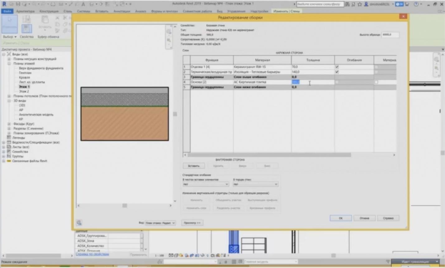
– Then, we define the materials for our walls, for our layers, and the thickness of this material. Even here we can change, make the brick laying of 380 mm. We can see the changes that immediately occured in the view. So, if I change the thickness here to 380 mm, then all these walls will change their thicknesses to 380 mm. Let's close this window for now.
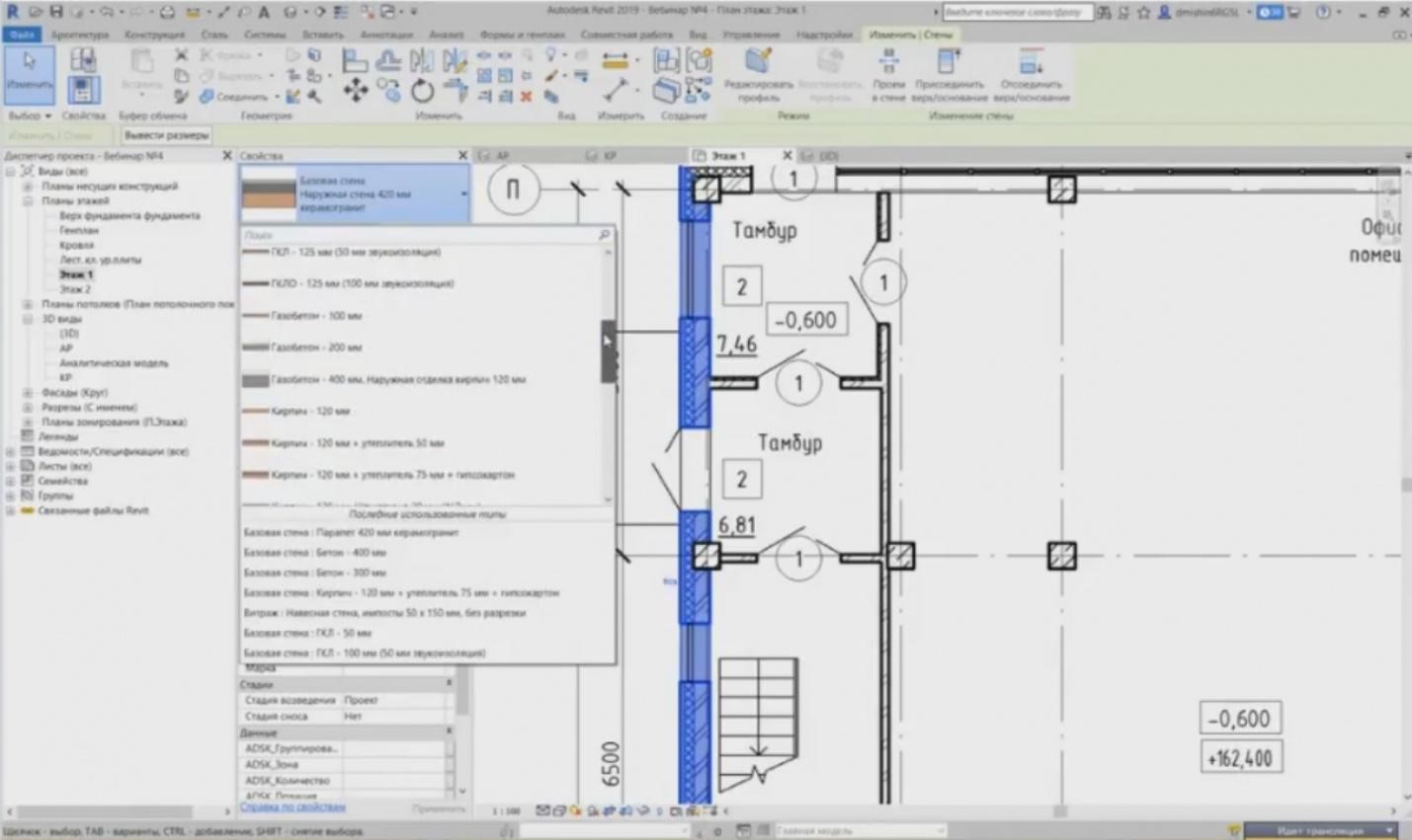
– I will not detail anything here as we have an introductory webinar. Let me continue. These are the base walls. If we open the list of base wall types present here, then we can see that there are many more of them than it is shown in the project. We have typical brick walls, walls with finishing, concrete walls, partition walls, etc.

- Let’s go on. Now, let's look at the structural elements. We have concrete walls below the level of the first floor. What is the difference between the bearing and architectural walls? As I have already said, they have a bearing structure. And you do not need to create the categories for the bearing walls separately. Any wall may be made a bearing wall. What can we do for that?
– For example, I can highlight any wall; this is the typical facade brick wall with finishing, and there is a “Bearing Structures” button in its properties. As soon as I tick it, additional parameters appear. It enables analytical model and reinforcement. And I can now reinforce this wall, make calculations with it in another software to analyze, and so on.
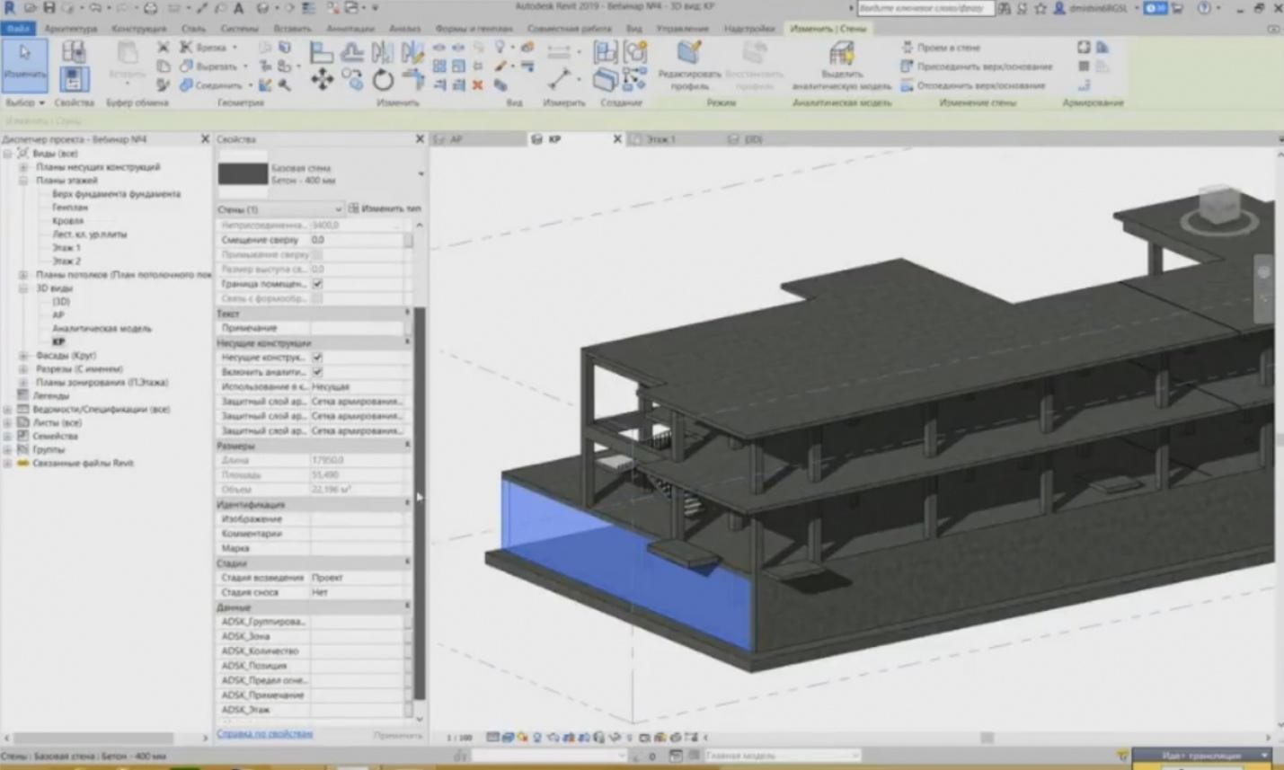
– We can see the same here. I highlight the concrete wall and we can see that it has such parameters.
– In addition to this, we also have the parameter for the bearing structure material. This tab, in the type parameters, where we set the materials, contains a tick “Structural Materials”, and the “Concrete” material will be included into the calculation during the design in a software for the product engineers. And the characteristics of the materials provided in this material will be used.
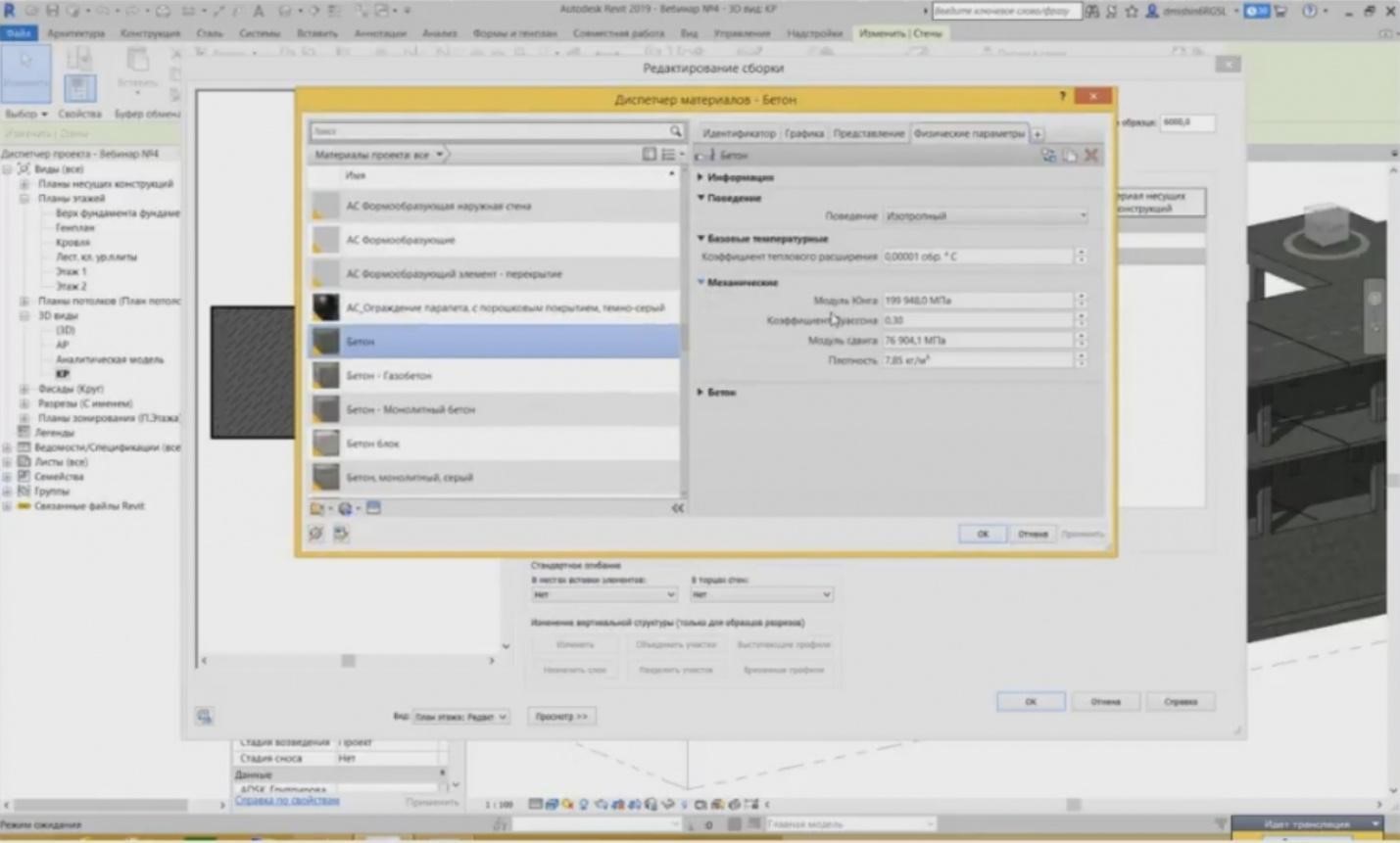
– You may go to this material. It has some particular physical parameters. They are provided here. They can also be changed. So, all of these parameters will be transferred to the design software and used there.
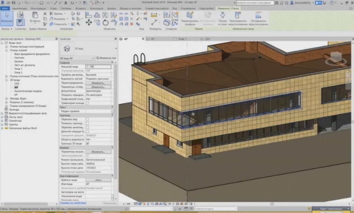
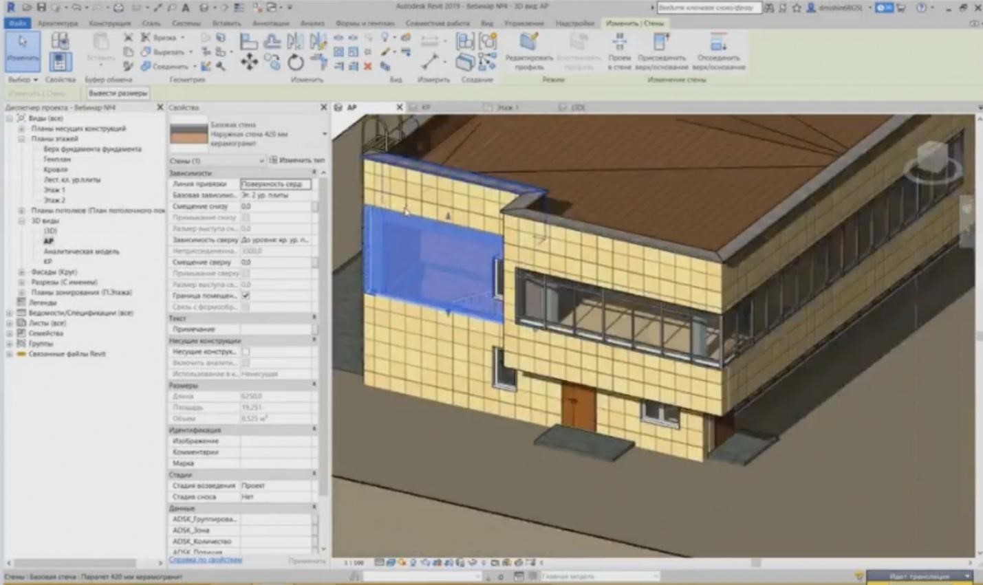
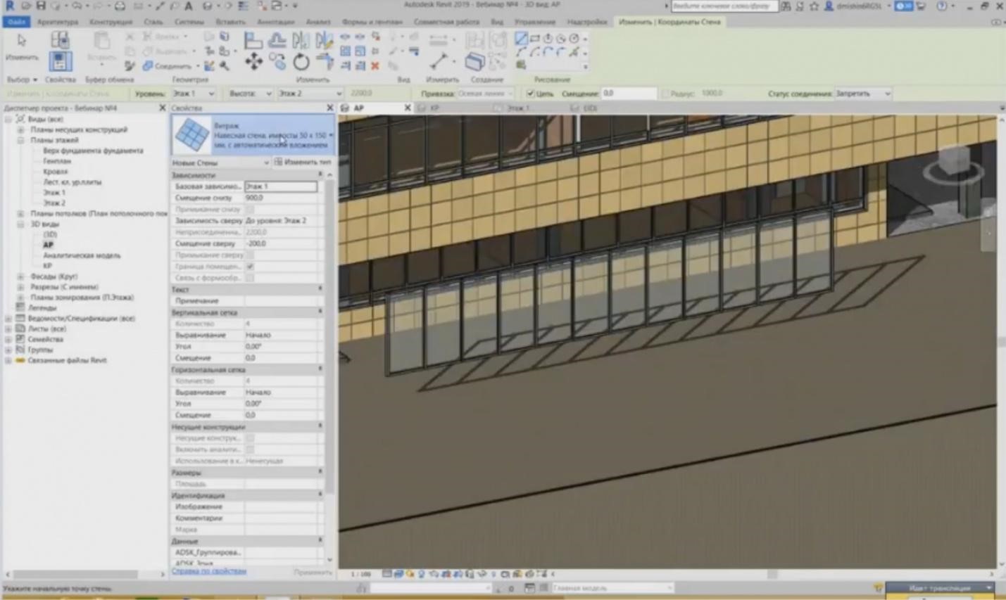
– Let’s go on. In addition to the typical base walls, such as bearing and architectural walls, we also have curtain walls. The curtain walls are also provided here. We can see such elements, i.e. curtain walls, in the facade. The curtain walls are also walls, but they work a little bit differently. How do they differ from the typical base walls? They differ in that they have no structure.
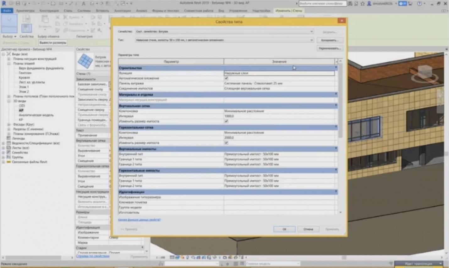
– If we enter the type properties, we cannot see any structure here. We cannot assign several layers for the curtain walls. A completely different picture is shown here. We can see the setting for the vertical and horizontal grid, providing the filling of this grid, and the impost for this grid.
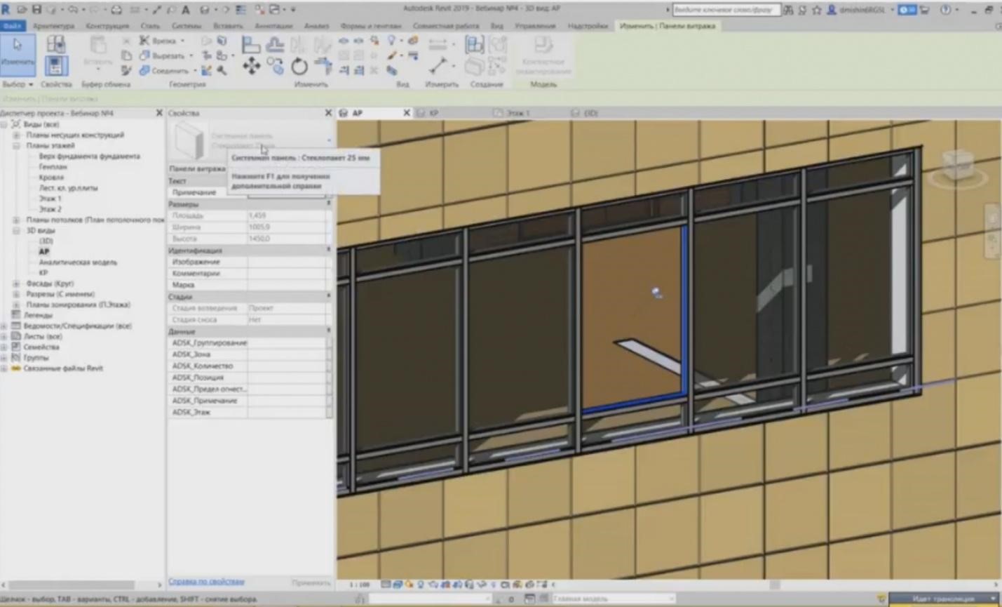
– So, our curtain walls belong to several families. This is a pretty complex system family. They consist of two types of families: imposts that are either horizontal or vertical elements, and, respectively, the filling between these imposts, i.e. the curtain wall panels. These are the panels. And the curtain walls are made such that we can replace any panel. For example, I can highlight one glass panel. The parameters also show in the properties that this is a system panel, the glass unit is 25 mm, and some of its characteristics are provided, such as area, width, height, etc. I can detach this panel at any time and replace it with another one.
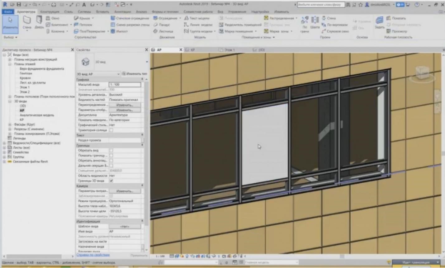
– Look at what is provided as a replacement in addition to the fact that we can use typical system panels; it will be a solid panel instead of glass. So, we have replaced it with a solid panel. In addition to the typical system families, we can use other walls or even other curtain walls; we can insert a curtain wall into a curtain wall. So, you can even insert a regular brick wall, which is present in the base walls, into this filling.
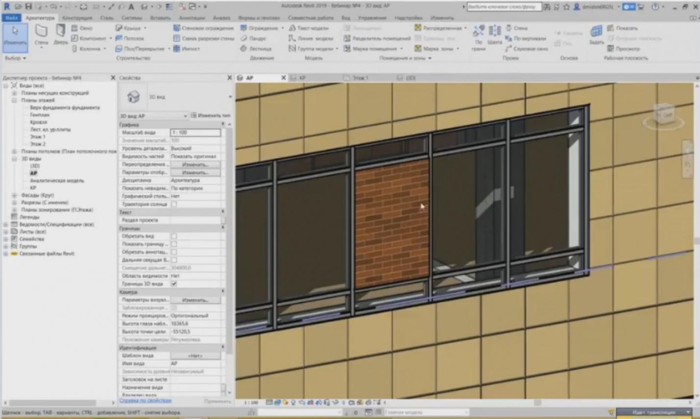
– We have inserted this wall instead of the curtain wall. This is, of course, rarely used, but in fact, it is used in practice in the situations when you need to insert the curtain wall into the wall. When do we have to do that? If you have, e.g., a false glass unit, you have a multi-layered structure, when the heat insulator is used, and also a finishing in the form of this false glass. Then you need to create such wall and use it instead of the curtain wall panel this way.
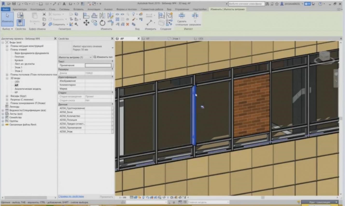
– The same can be done with imposts. We can detach it, or even several of them, at any time and replace it with another type, such as, e.g., use a circular impost. Let me continue.
– In addition to the grid we have, which is created automatically. If I draw a curtain wall nearby, you will see that the grid is created automatically. In addition to the fact that the grid can be created automatically, you can also create it manually.
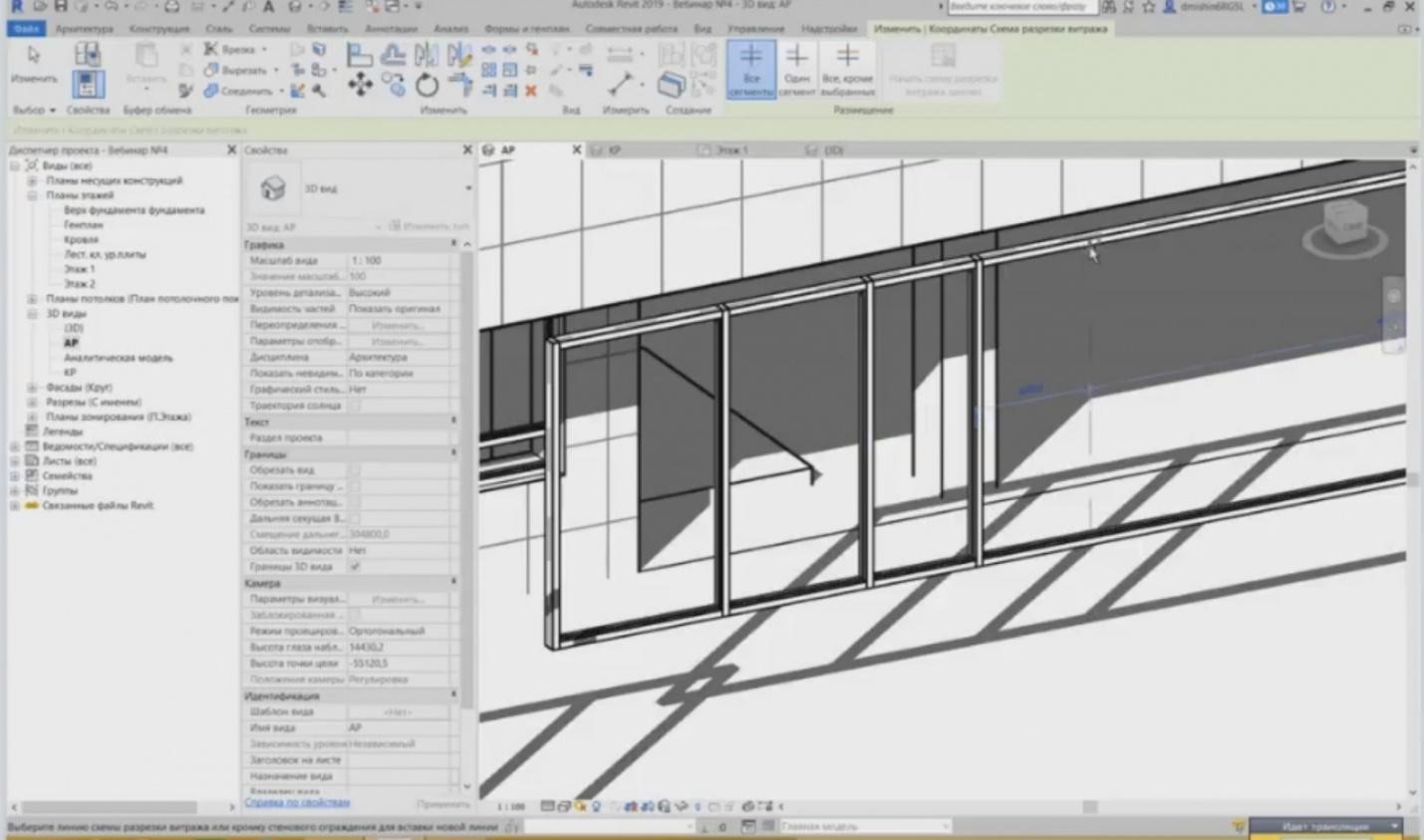
– If I draw the curtain wall without the grid nearby, I can set it the way I wish using “Wall Cut Profile” tools. You can specify vertical and horizontal elements. For example, a dotted line appears and it indicates the distance at which I will place this element. These are two temporary dimensions: 1.1 meter and 6.2 meters. And I can create any grid I need, with any step. If the step here is even, then I can set up any step both vertically and horizontally.
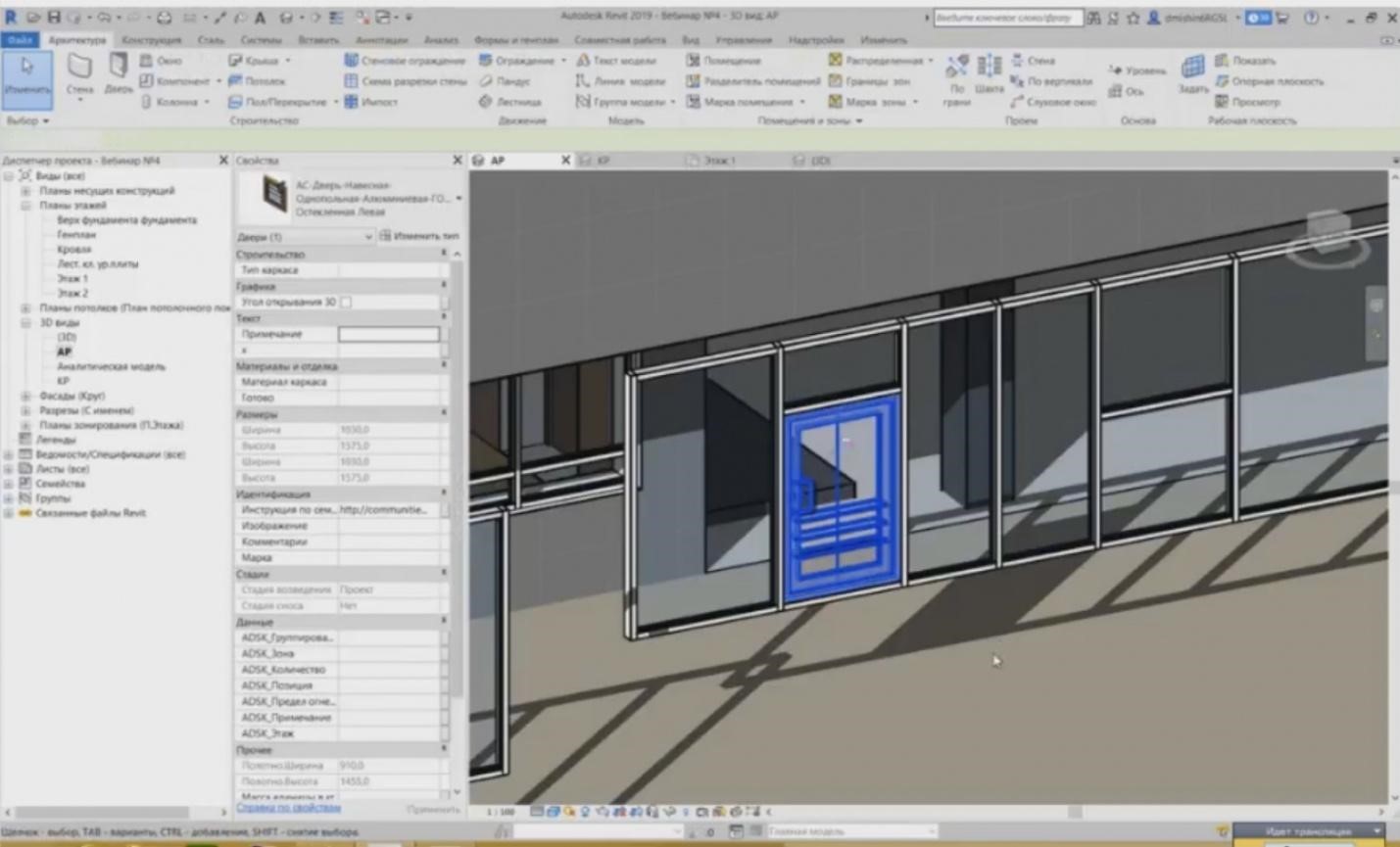
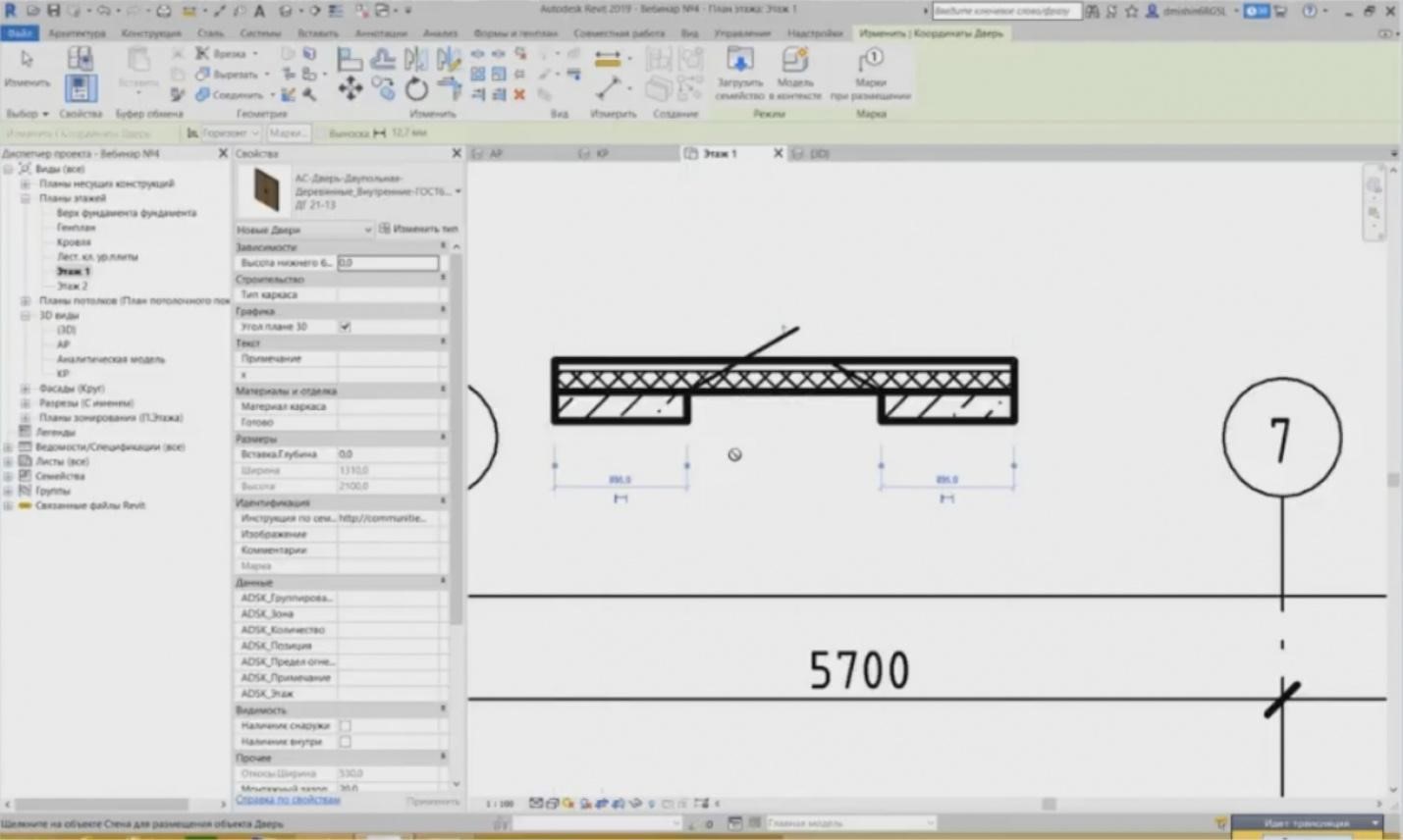
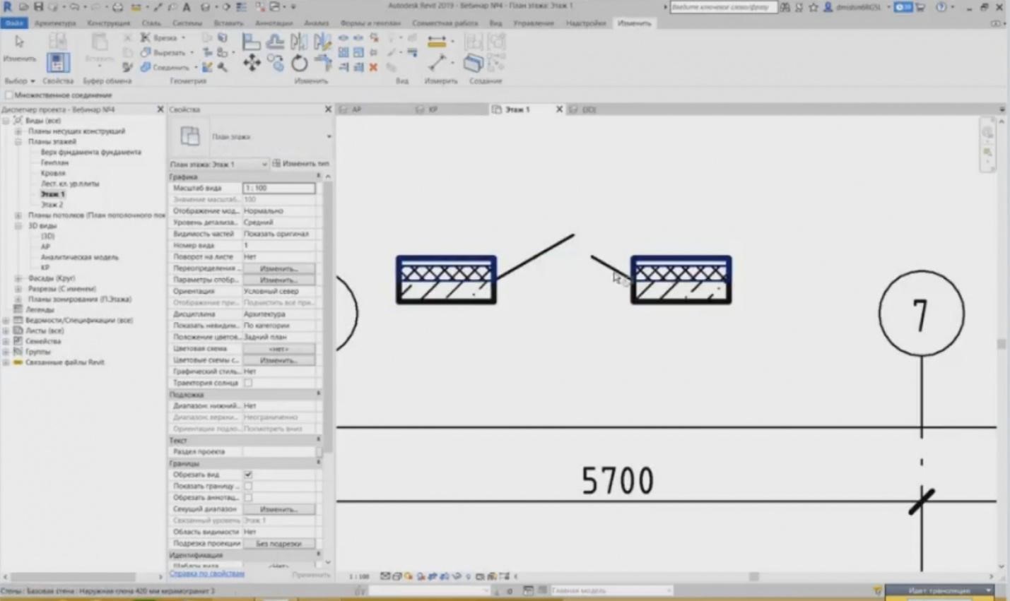
– There is a good function for the curtain walls, i.e. setting up the stained glass window for the door in the panel. If I highlight this system panel, then in addition to the fact that I can embed the brick wall here, I can also embed the door. The doors are also provided in the element list, and you may insert them in the curtain wall panel. We also have a hanging glass door in the uppermost. For example, you can define one-part or two-part door, either left, or right. We can choose it and you can see here that the door has been placed.
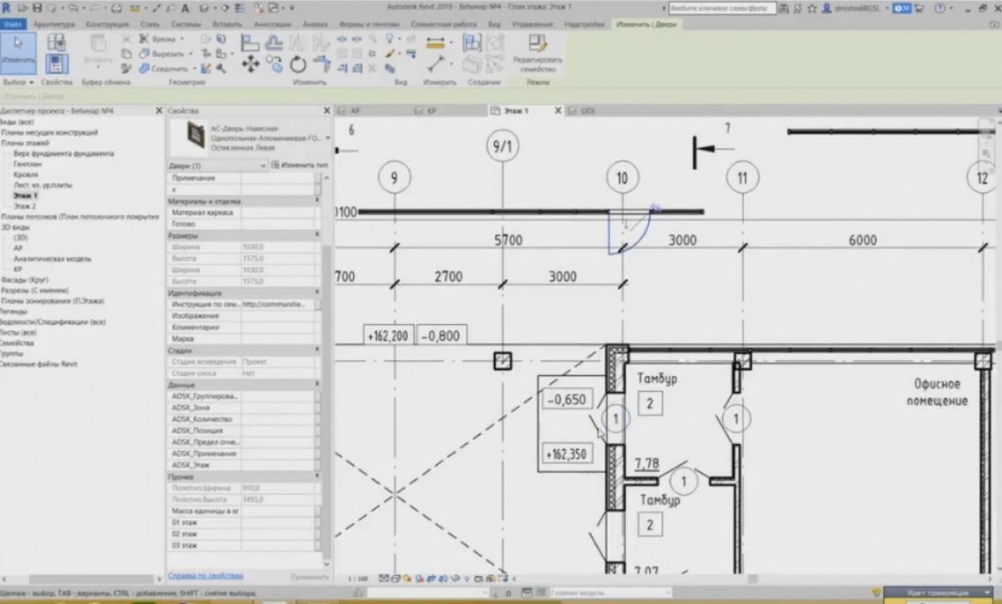
– And in the plane; I will go to the floor plan; this door is shown as the door. You may mark it. It has all the parameters typical for a regular door. If I compare it with this door, then you can see all parameters: grouping, zones, number, position. All these parameters are also present here. You can also define them and they will also be added in the Bills of Quantities.
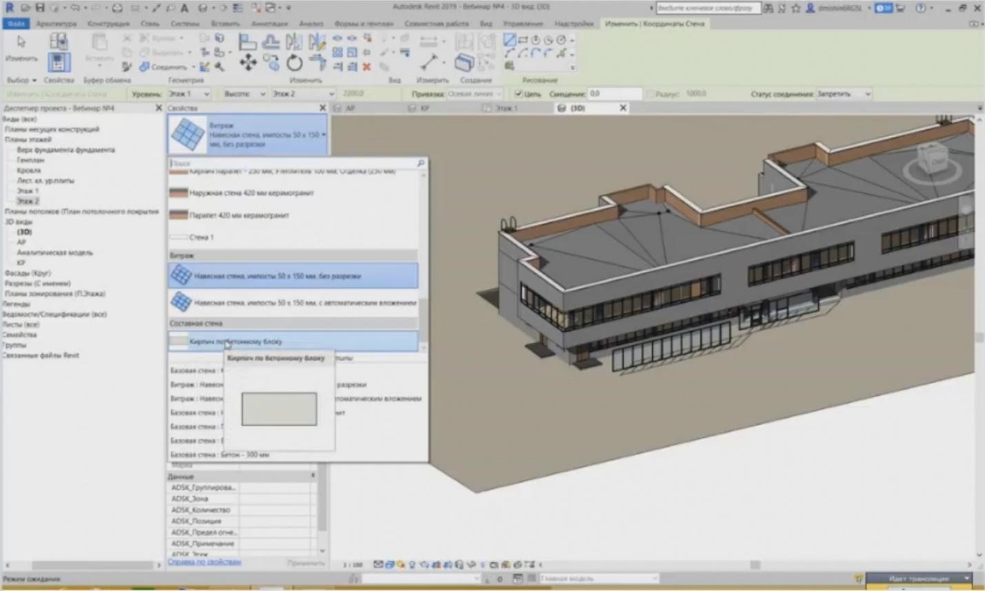
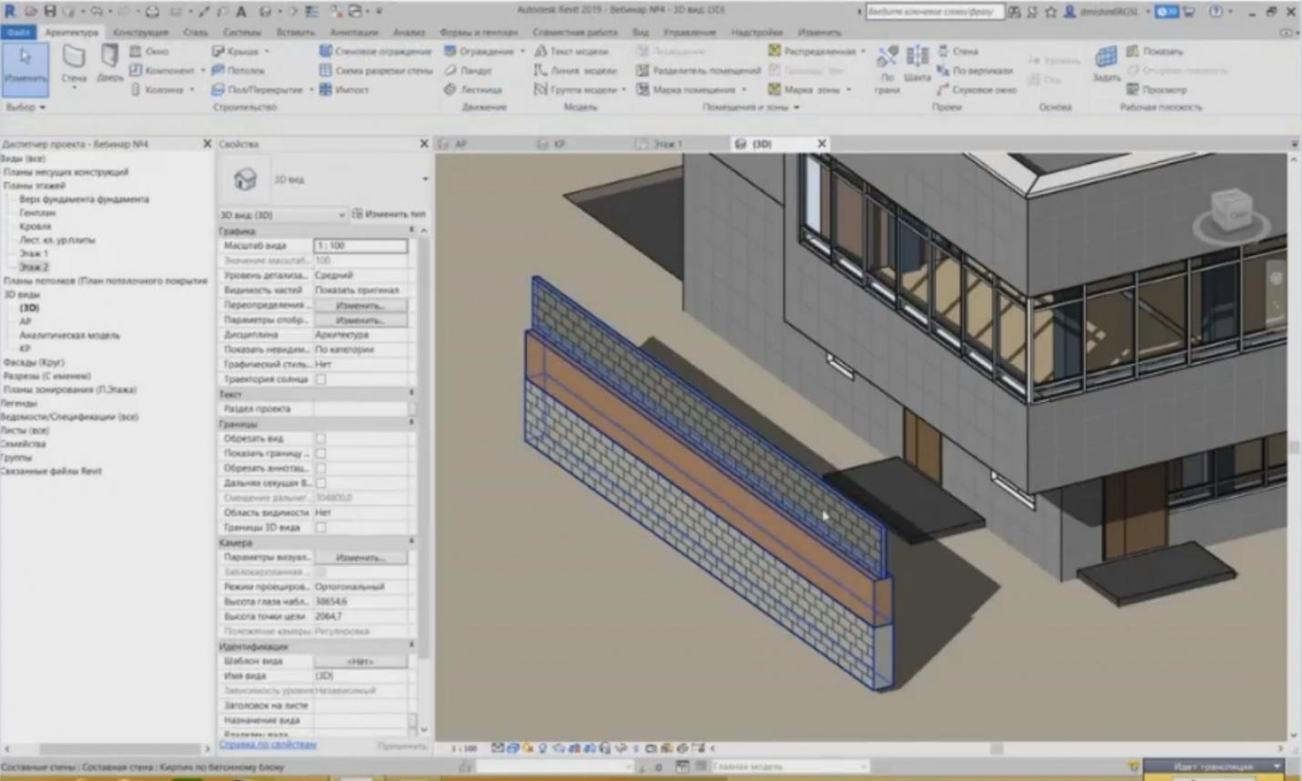
- Let’s go on. And the final wall type we should consider is composite walls. Actually, the composite walls are rarely used. They are not very comfortable, but this is, of course, my opinion; perhaps, somebody use it, but I use them rarely in my practice, or I can even say never. The last subcategory is a composite wall. Here you can see only one instance provided, which is called “Brick on a Concrete Block”.
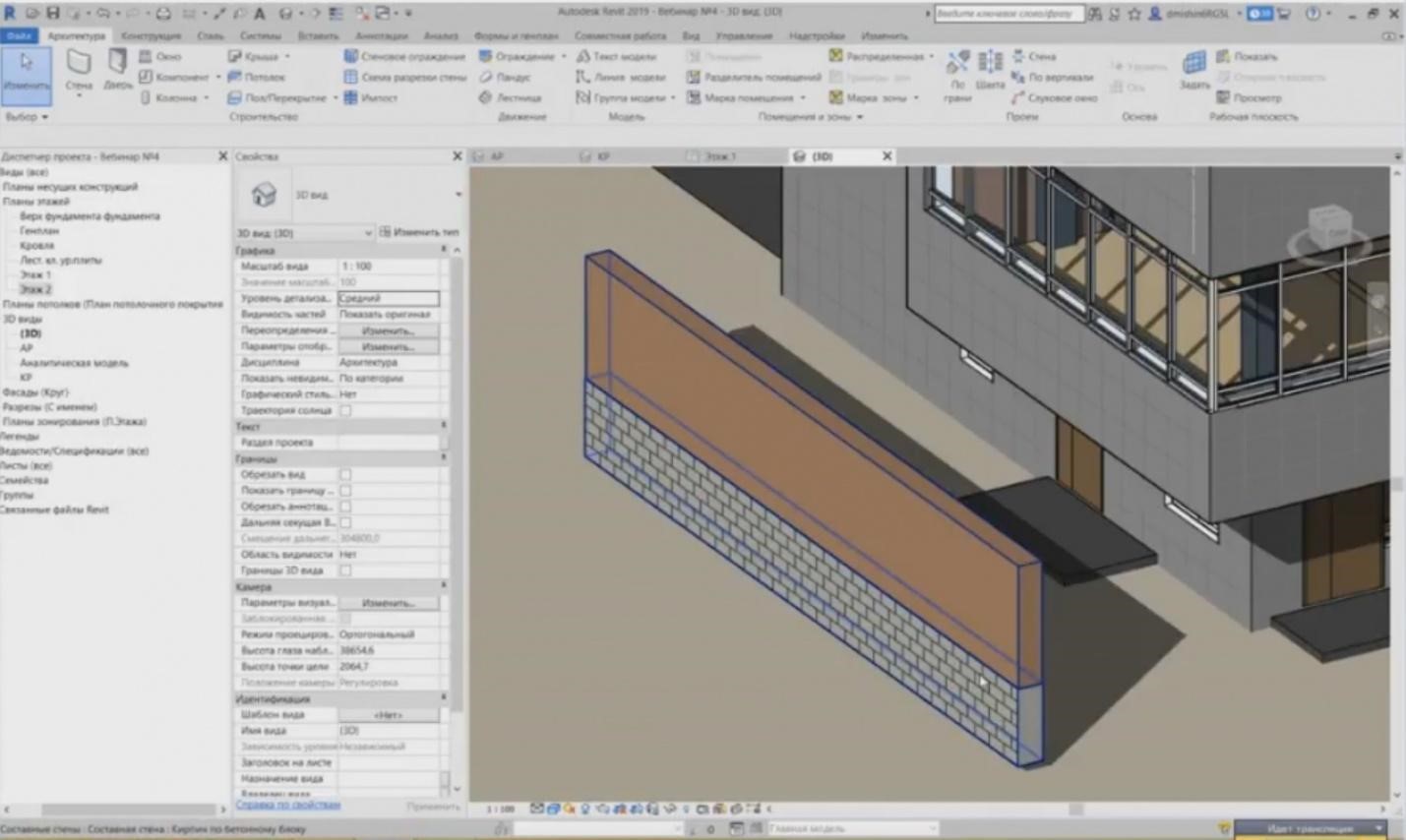
– If I place it, let's see what it will be. You can see here that this wall is divided into two walls horizontally. At the bottom, we have concrete blocks while at the top there is a brick laying. All of these parameters we have for the base wall are available for the composite wall as well.
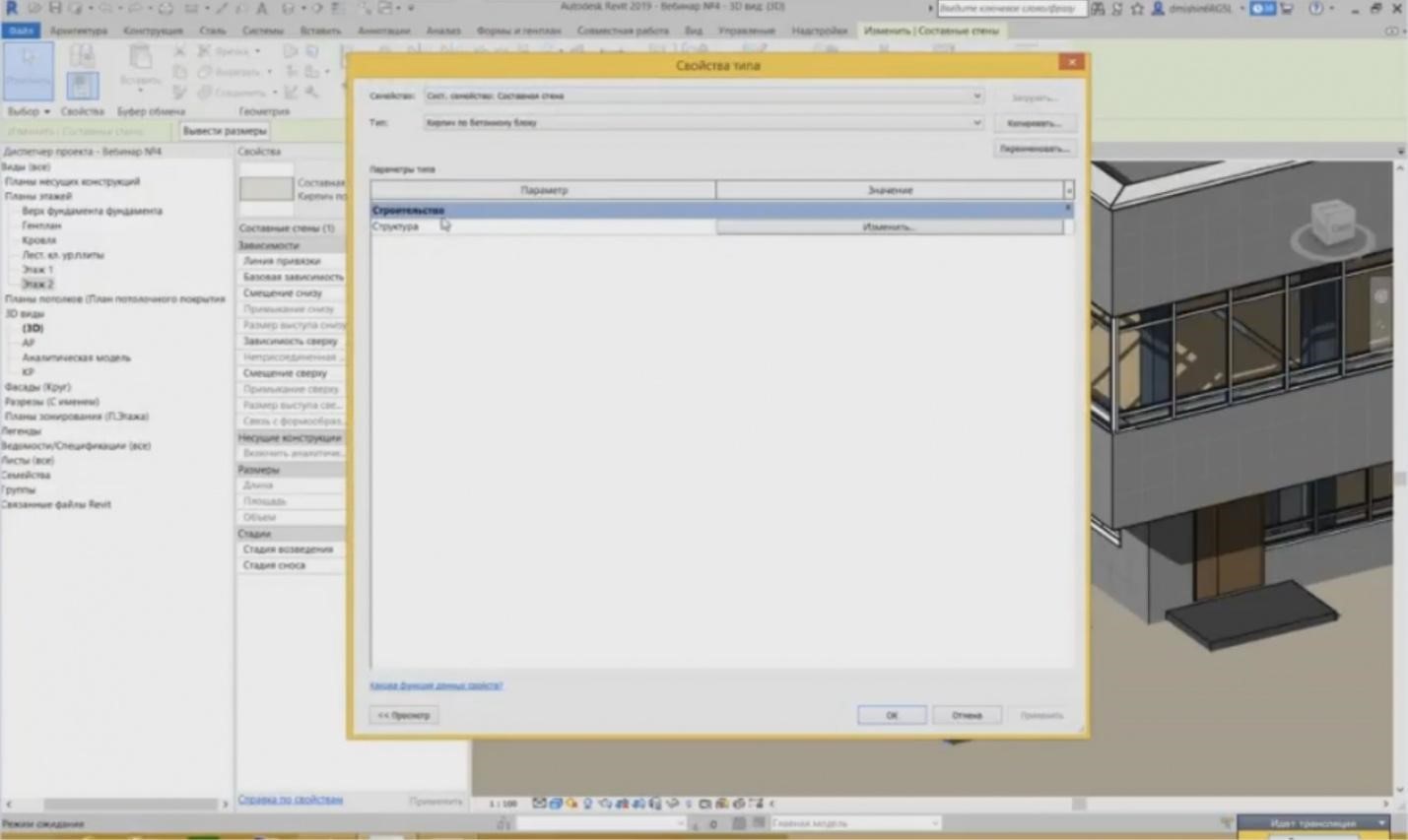
– But if we go to the type properties, you will see that we have no parameters at all. Why is that? It is because the wall consists of two base walls and, respectively, if I want to change the wall, I need to change the base walls.
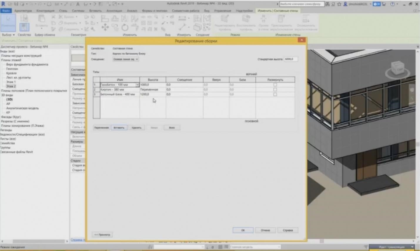
– In the structure, I can set the number of walls that will be used, e.g., insert one more wall on the top. And if I, for example, set the height, it will be one meter in the beginning; it will be a variable. The brick is used here, so we set “Porous concrete — 100 m”, and press OK.
– A wall at the top has appeared; it is 100 mm and, thus, three walls are created at once. Why are they rarely used? It is not really convenient to work with them. Sometimes, it is easier to create three separate walls with different offsets from the level. The first wall, as you can see, its offset is set automatically at 2.1 meters. Then, the next brick wall has the offset 1.2 meters and the last one has the offset 0.0. And then work with three walls separately.
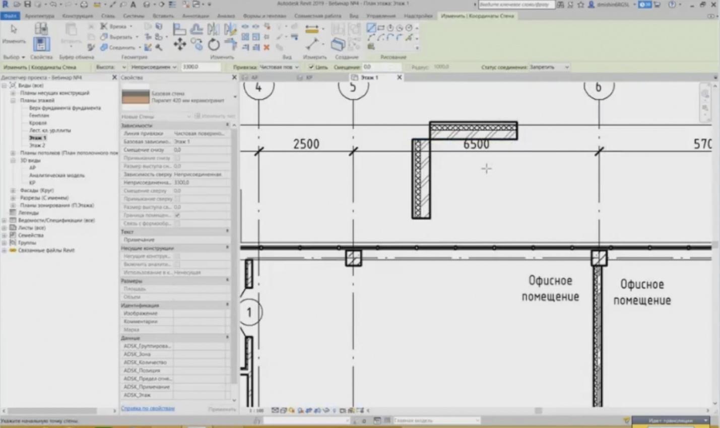
– Let's talk about the specific features; how to create walls? What rules are usually applied in this case? The first rule is that the architectural walls are separated from the structural walls. And now, the product engineers and the architects work in different files; even if they work in the same file, it is better to separate the architectural and structural walls. How can we understand this? I will show you an example. If you need to create a wall with a bearing element, e.g., concrete. Let's copy and set here the bearing layer of concrete instead of brick as a core. This is concrete. Here is how my wall is shown. It has a bearing layer that will be transferred to calculation used by the product engineers. And there is an architectural wall: it is a heat insulation and a finishing. Thus, when two specialists work, i.e. the product engineer and the architect, you must separate these walls. Create a structural element separately and create an architectural element separately.
- It is easily done. First, we create a concrete wall, and then we create the same wall without this bearing element. I delete it and leave the heat insulation and the ceramic granite tiles only.
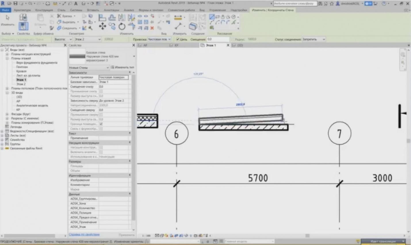
– And I create it this way on the internal surface. This is done as follows. You have a product engineer working with his wall, and an architect working with his finishing separately. In total, you will obtain the same wall.
– Surely, there are some nuances, when the architect installs a door or window openings; in the multi-layered structures, they cut through the entire wall, but here, if I install the door, then only one layer will be cut through.
– Although there is a solution for this. It will be solved if we combine these two walls using a “Join” button in the “Change” tab. The door inserted into the structure cuts through the structure and the architectural wall. The same is true for the finishing. If you need to set the internal finishing, then the walls with the finishing are created separately. The plaster is 20 mm, a thin wall, it will be present.
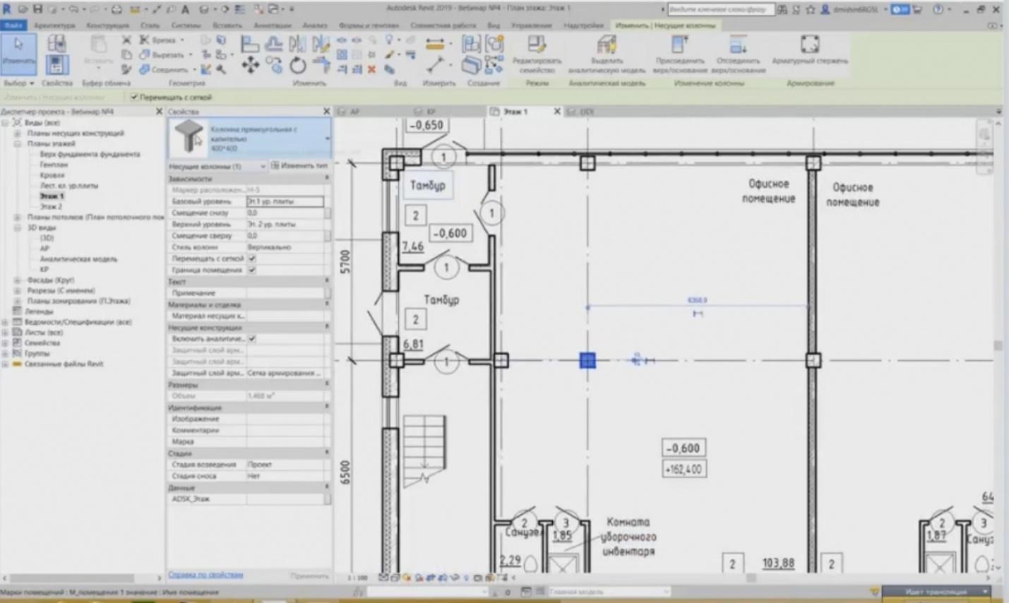
– So, let's go on. Here, in addition to the walls, we also have columns. The columns are not system families like, e.g., walls, but loadable families. To load a column family, we need the file for this column to load it into the model. We have two families here: a column with a cap and a column without a cap.
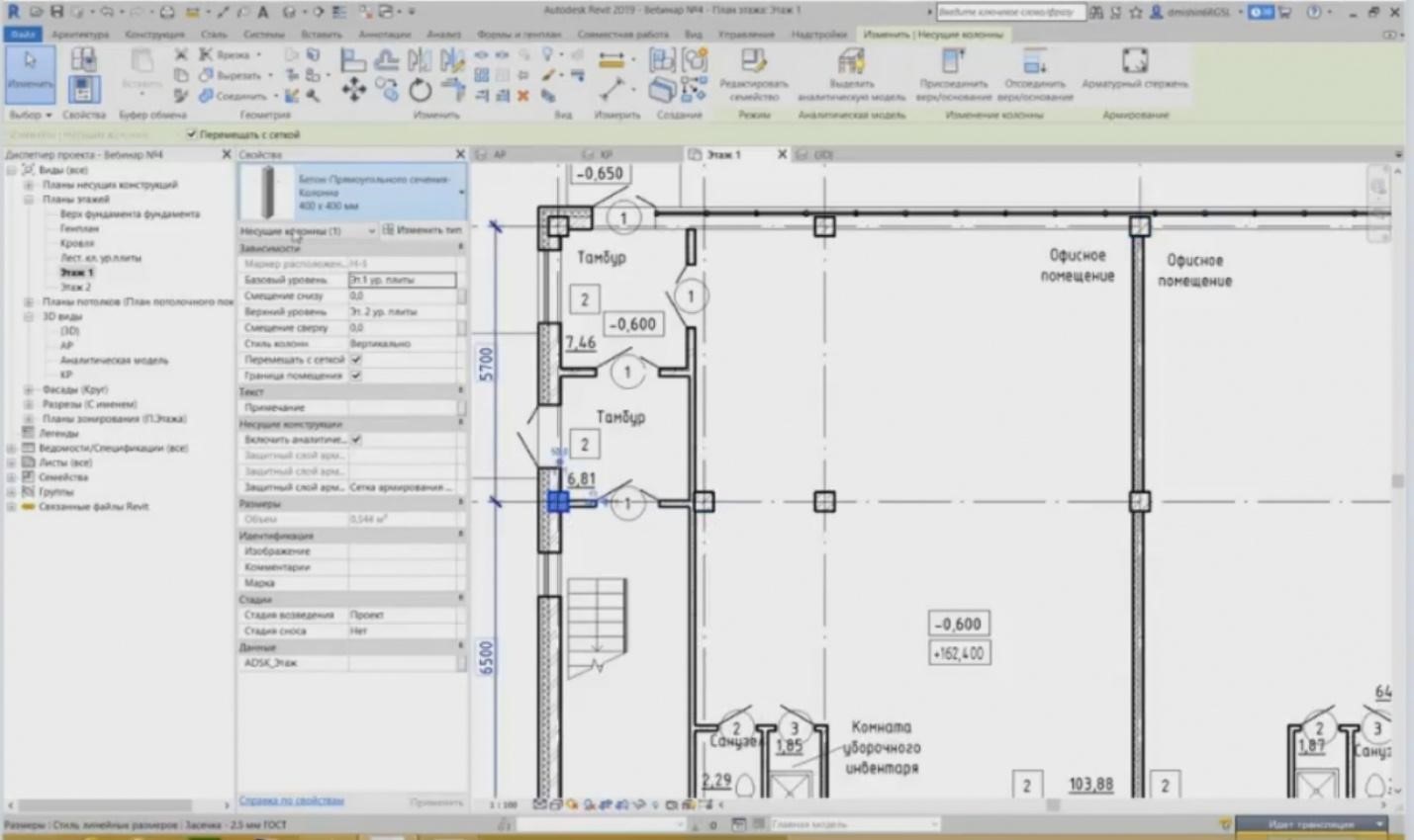
– I will show you where it is shown. Here is the column without a cap. What is the column’s specific feature? The columns are also the elements that are tied to a particular level; they also have the offset from the bottom and the offset from the top, just like the walls. They have an analytical model and they can also be included in calculations. They can also be reinforced and any list of parameters can be set, e.g., the width and the depth of a cap. Here is also a specific feature.
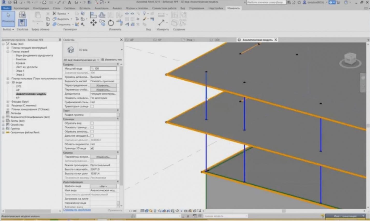
– Let's take a look at the analytical model. We have analytical models for each element; it is a vertical line for the column. The analytical model is provided here in the 3D view, we may look at it. So, this is our column. As shown by the practice, it is really a line for the typical columns. But columns with the caps here should be a little different. The cap must also be included in the calculation. And we can see here that our column has a cap. You can read “Form and Size in a Family”, “Rectangular Column with a Cap”, but the cap will not be included in calculations. And the product engineers have solved this issue by providing a cap as a separate floor. We will get back to this later. Intermediate floors also have analytical models. So, if you provide a cap as an intermediate floor, you will have another analytical element over the column, and this analytical model can be used in calculations. This is how they did it.
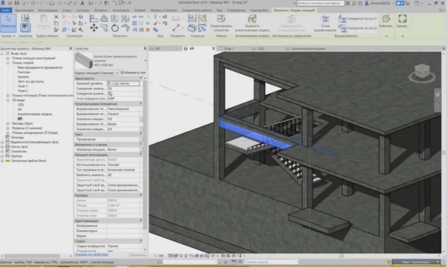
– In addition to the columns, we also have intermediate floors and beams as bearing elements. The beams are also tied to the levels. We also set the offset relative to the level and set the parameters for calculations: what material will be used for bearing structures, whether the analytical model will be included, etc. The analytical model can also be viewed here.
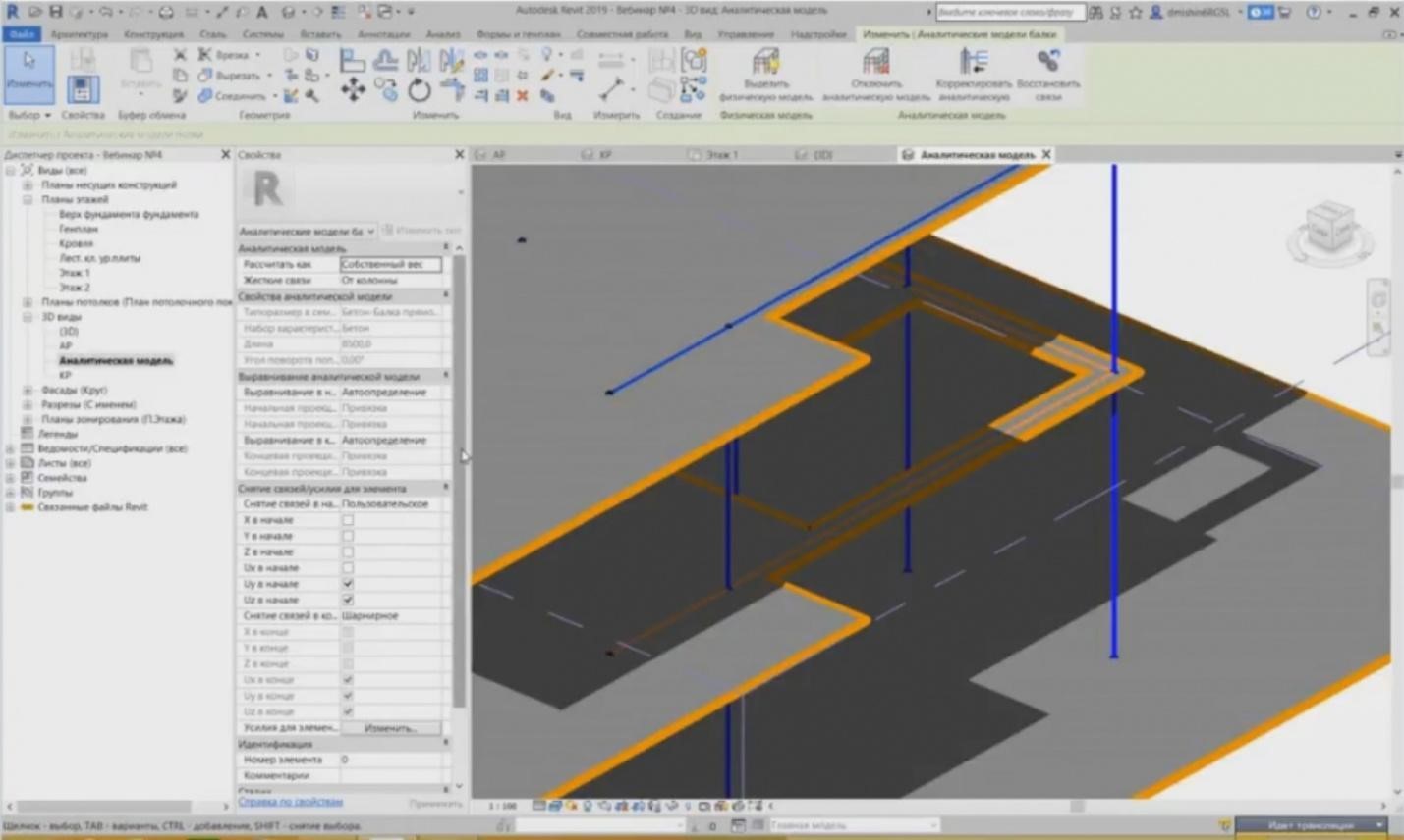
– These are the analytical models for our beams. They are colored in orange. Here are all parameters required to create the calculation. Of course, Revit does not calculate anything. In Revit, you can collect loads, but then, in the course of calculations, you should use some other software suites.
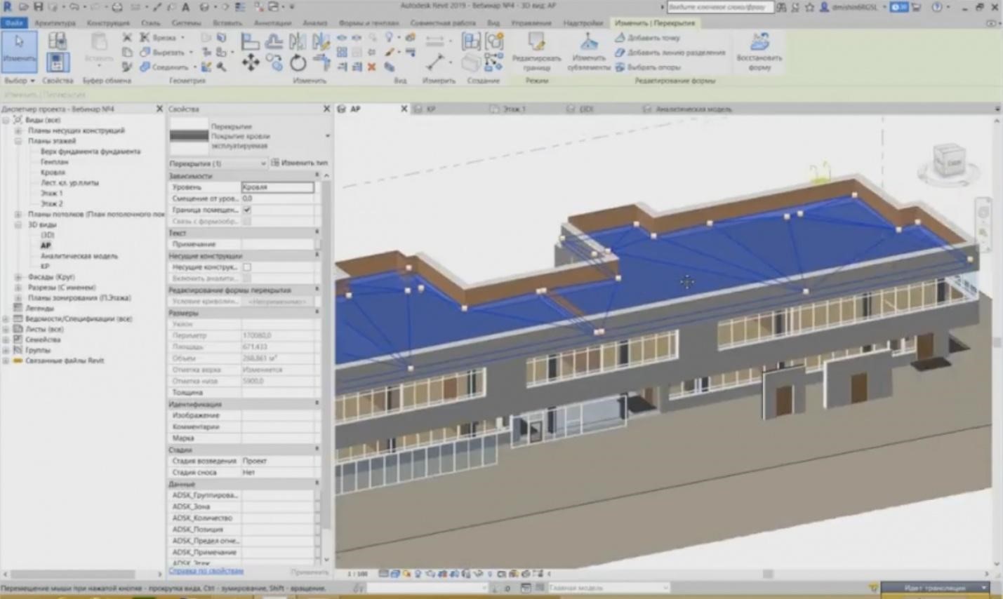
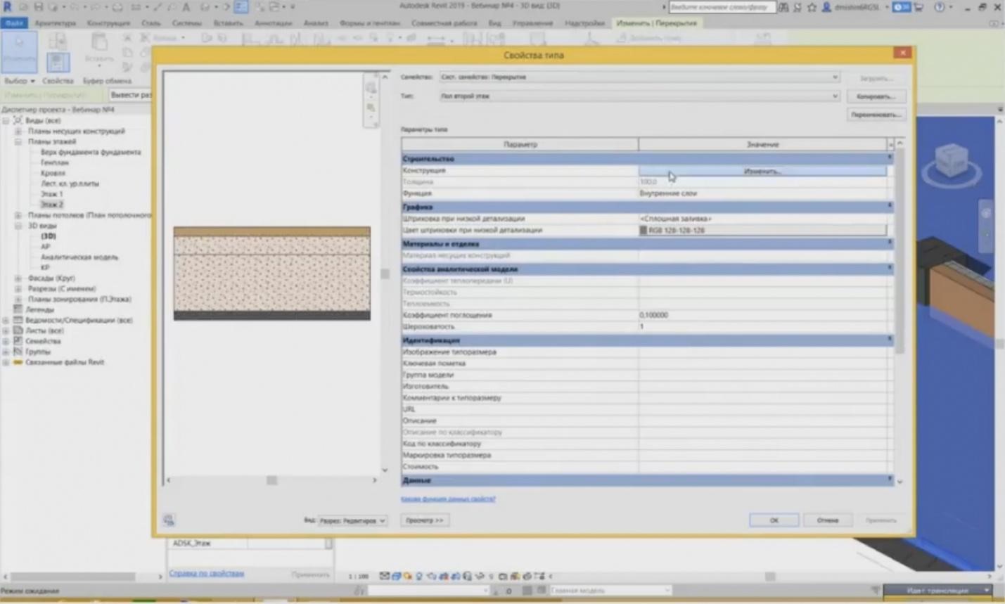
– Let's go on to intermediate floors. As well as the walls, they may be architectural or bearing. What do architectural intermediate floors include? These are floors and coatings, e.g., of the roof, for the passages, i.e. everything that does not carry any load but is a load. Similarly to the walls, the same principle works here: we should separate structural elements from architectural elements. You do not need to create a common structure with the structural element and with the architectural structure for the “pie” of the floor or the roof; you should separate them. The same structural parameters are completely the same. Let's choose this intermediate floor named “Roof”, go to the type properties, and it also has a particular structure.
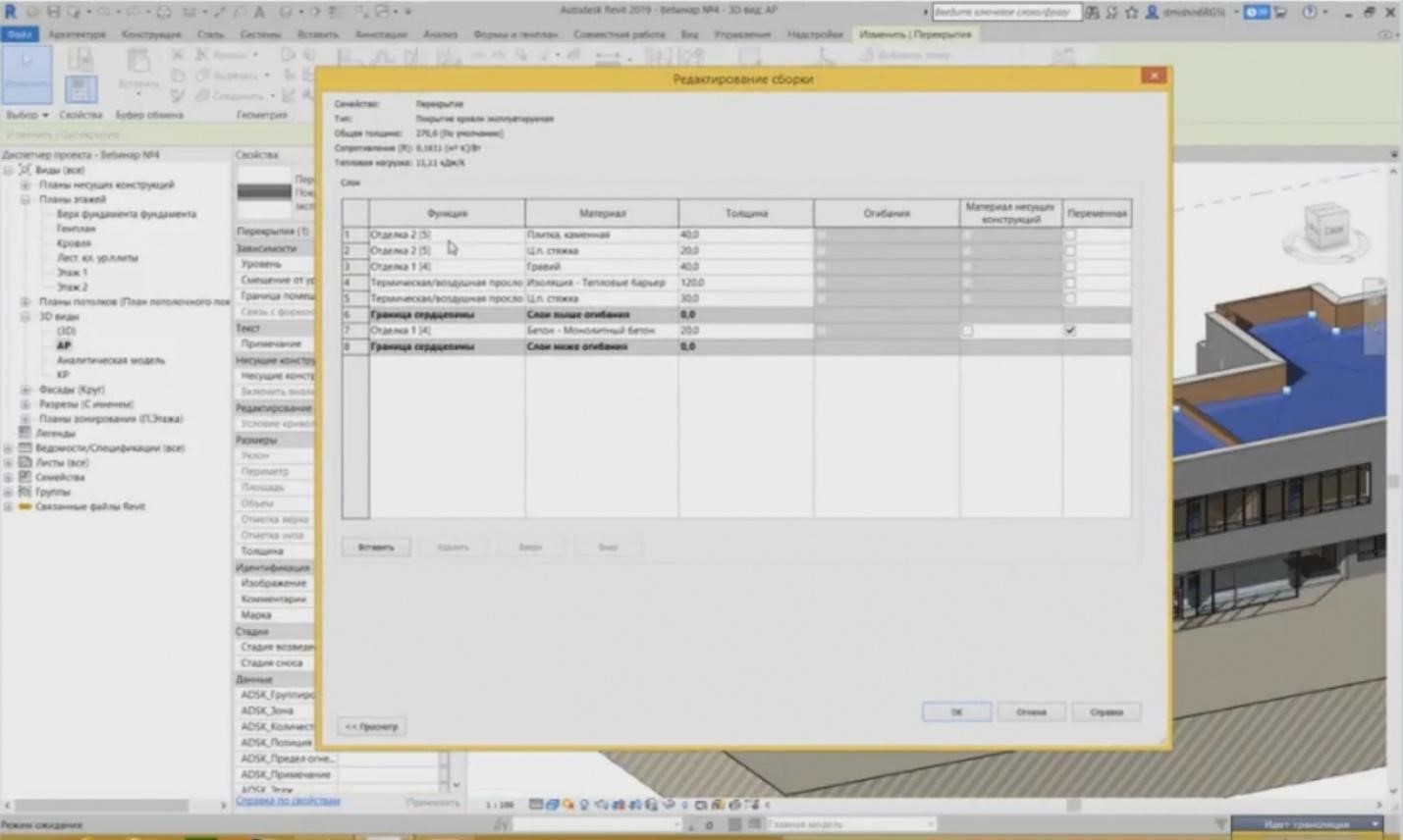
– If I press the “Change” button, then I can see the same table as for the walls. We also set the layers for this structure; each layer is assigned a function, a material, and a material thickness. And then this “pie” is created.
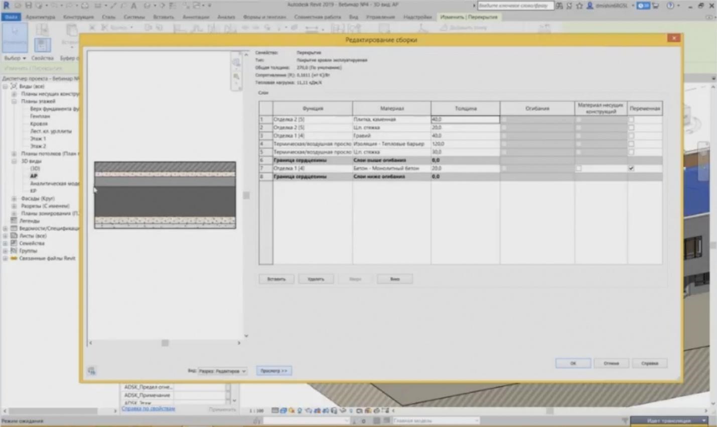
– You can see it here.
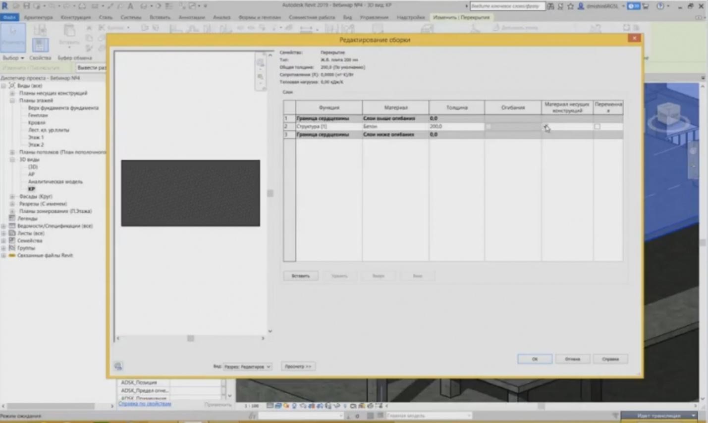
– The same thing can also be created with the structural elements. But it is clear that it will be a little bit easier. There is no large structure here. It is only one layer, from which the material of bearing structures was defined for calculations.
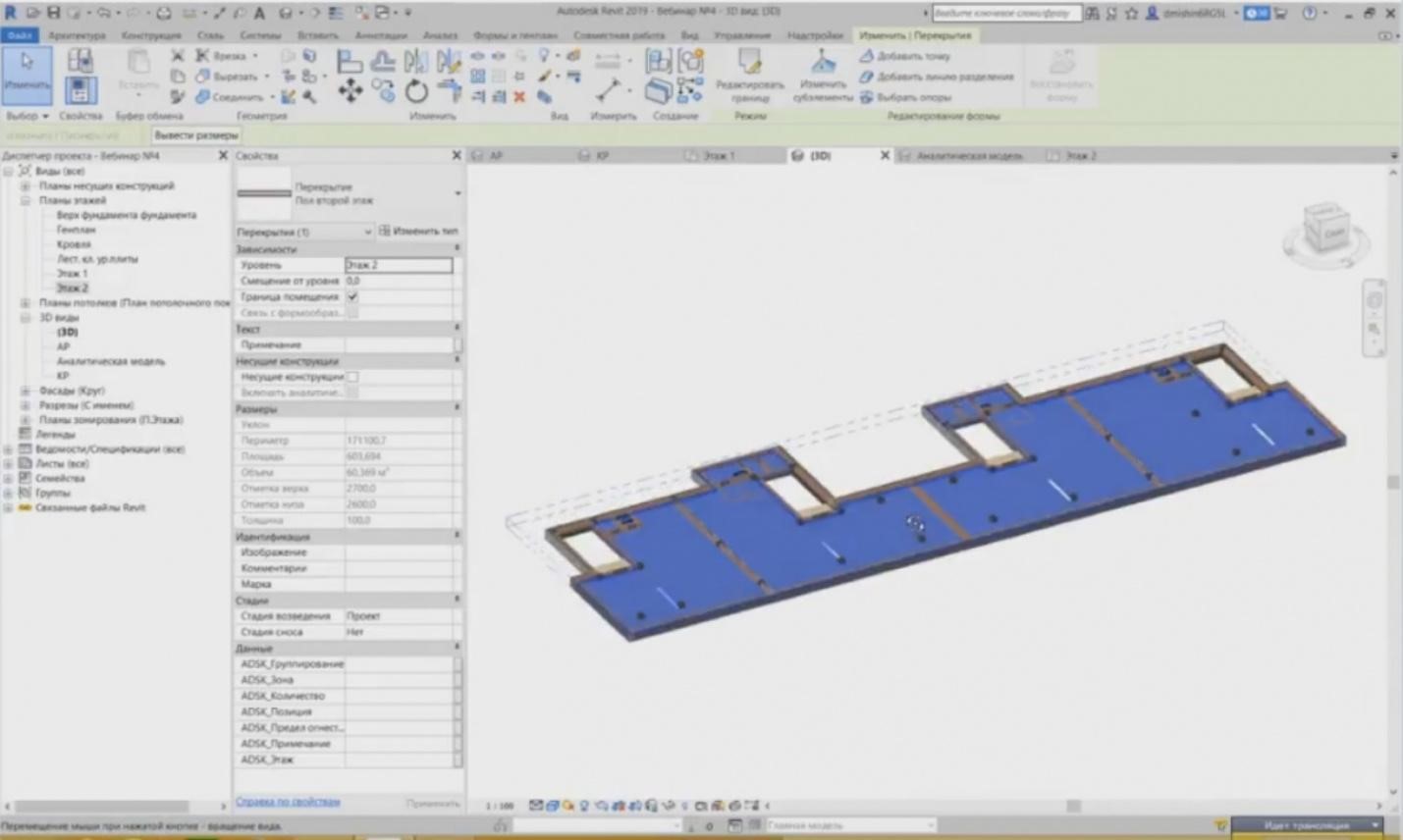
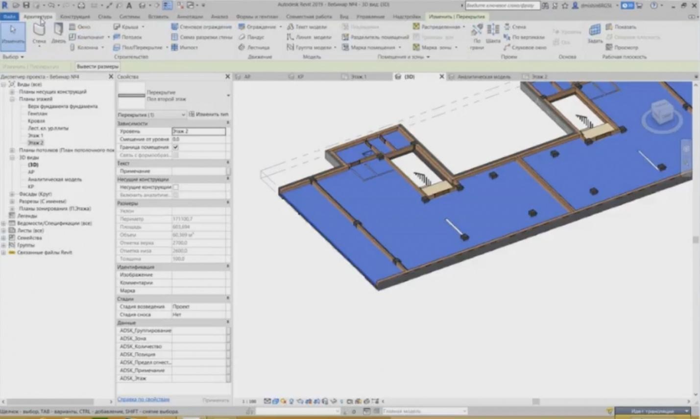
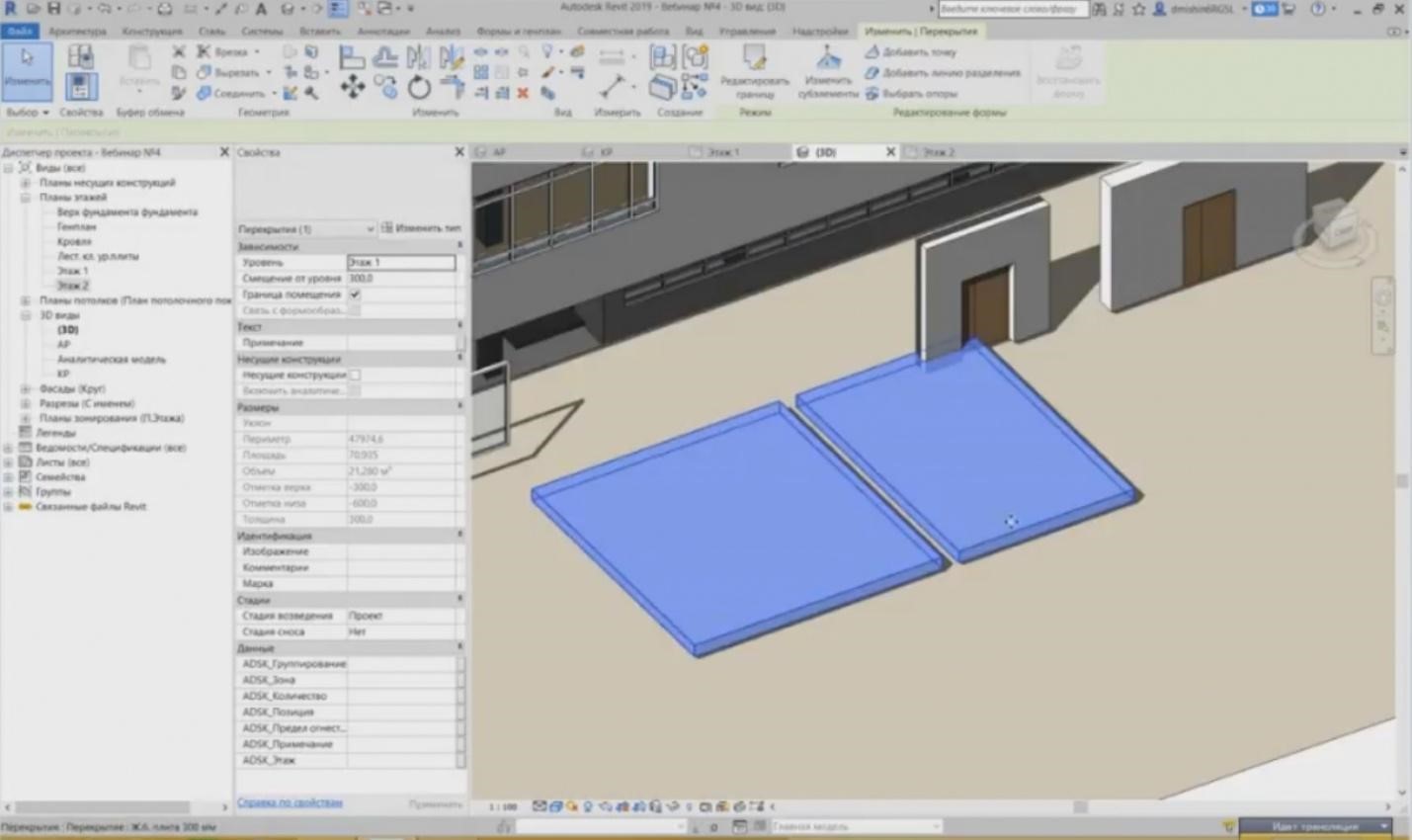
– This is also true for the floors. Let's go to the second floor plan. If we take a look at the floor, we have a room here, and we can highlight the floor on the second floor. You may see it in the 3D view for convenience.
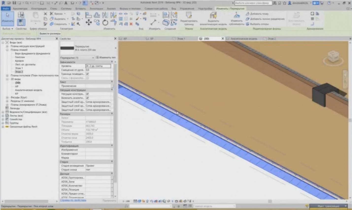
– And you can see that I have a separate floor element and a separate intermediate floor element.
– I can go to the floor element in a similar way to see what layers are enabled there. Surface casting, sound proofing, and finishing.
– How are intermediate floors created? If the walls were created by indicating the start and end points, then it is a little bit more difficult for the intermediate floors. To create an intermediate floor, we have to define a contour. If I need to create an intermediate floor, I press the “Floor / Intermediate Floor” button in the “Architecture” tab.
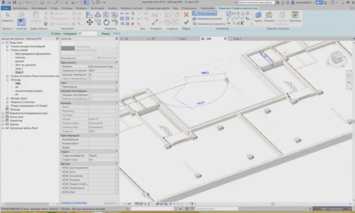
– Revit enters the editing mode. The buttons appear such as a tick with the crossing. The panel becomes disabled. Nothing is enabled. So, drawing tools are provided here, using which I can define a particular contour for the intermediate floor. You can use lines or rectangles, etc. There is also a rule you have to follow: do not create more than one contour.
– I will turn on the representation of the entire geometry. I will create the intermediate floor again. For example, if you need to create two adjacent intermediate floors, even though they are completely similar, you do not have to create two contours. Revit will allow this, but it will be considered a single piece. This is not correct since the elements are separated. There should be two elements instead of one.
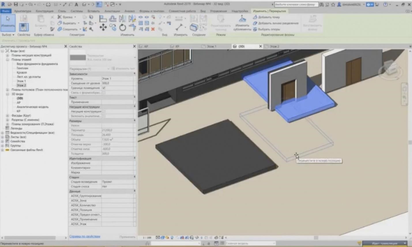
– So, if you need to show two intermediate floors, even if they are the same, you can create the contour for one of them separately and then create a similar intermediate floor nearby for another intermediate floor, so that these would be separate elements. There are two such rules: the first is the same as for the walls, i.e. to separate architecture from structure, and the second is that only one contour should be present in one intermediate floor.
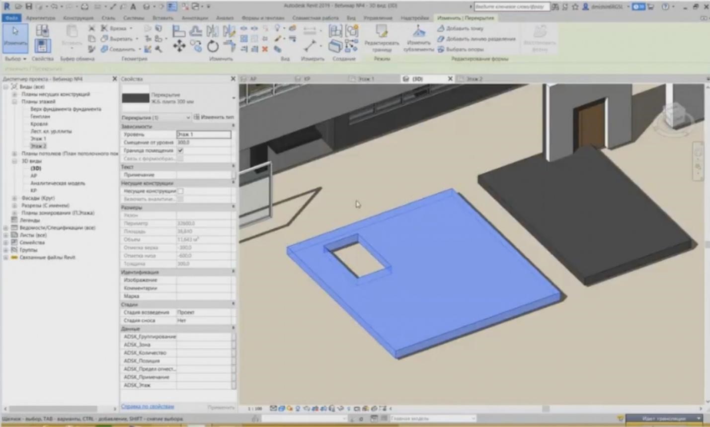
– To create any holes, you may use rectangles inside the contour this way. In this case, the element will be cut.
– That's all for today. Thank you for attention! We can proceed with the questions. I hope that you have questions. Unfortunately, I have not seen them yet.
– Question: “If the walls may be “joined”, can we also “detach” them?”
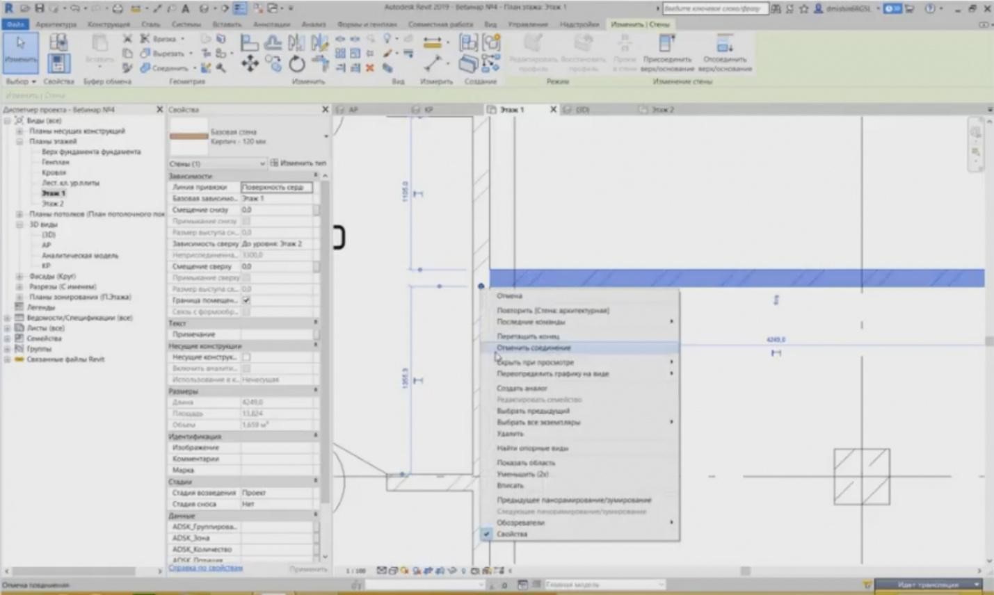
– There is a good function, indeed; when I discovered it, I was happy because sometimes, Revit joins walls incorrectly for me and I had much trouble with this. For example, if you create a wall, draw it, then, in the editing mode for this wall, you may detach it. You can see that it has automatically joined. If I right-click this small blue circle, this blue dot, then in the drop-down menu, I can see the “Unjoin” button. You may press the button and the wall will be disconnected from this side only, so I can place it anywhere I need. Upon pressing this element, this icon, it allows new connection, and I can join it the way I need. If I press “Join” again, it cuts. Therefore, it is a very convenient tool for the points where we do not need a connection.
– “The integral wall and the “joined” wall have been differently cut by a door, why?”
– Yes, if you take a look at these two walls, the door is inserted into the structural element, into this wall. And the door is always inserted along the surface of the wall. If I inserted it into the wall with finishing, then I would have the same picture.
– “How much time have you spent on studying Revit?”
– Sometimes, I discover new features, especially when they add something new in new versions. But really, two years were enough to study the software.
– “What else in Revit does not always work correctly?”
– Sergey, you know, frankly, there are some points and there are many of them in Revit. I will not list them right now, but indeed, when you start working with Revit, you will see them. Actually, you may always find a solution for any shortcoming, which allows solving the problem.
– “And probably the most important question: does Revit support our standards for styling the drawings according to the effective GOST, or only foreign standards are used there?”
– This is indeed a good question. Yes, it supports GOST. We have intentionally created the templates containing this stylizing feature. These are the fonts and all elements you need as well as annotations used for stylizing according to GOST. Some specific points are hard to implement, but you can also do that using the so-called aids. I will provide a specification issue in Revit as an example. If you look at specifications in Revit; I will open a specification on the sheet, and we can see here that the height of the string is 5 mm, while according to GOST it should be 8 mm. But in fact, I have not yet met such experts or quality control that would reject this; they accept 5 mm. Indeed, you can achieve 8 mm using some aids. There are such stylizing aspects, but you can correct them. And here you can be sure that all sections may be produced from Revit, this is what many organizations do today.
– Stanislav, I am going to answer a question now. Victor has asked the question. I will repeat once again that we will have a webinar record; we will process the record within several days and publish it on the website, and after that, we will send it to the e-mails you have used to register for the webinar. The record will be available. Then, as far as I understand, the question was about how much time you need to study Revit. Victor, please detail, at what level? The answer is that he meant in general.
– In general? I think that, to design, if you have a template and if you have passed a training and did not have a pause when you did nothing, i.e. you have passed the training and immediately started working in Revit, then I think that 3 to 4 months will be enough to study the software in full and produce documents. Of course, self-study takes much more time.
– “Will we have a lesson on creating and assigning textures to the surfaces?” I am telling you right away that no such lesson has been scheduled. And the second question: “Has the webinar to work with the families been scheduled?” It has not.
– I will send a link to the webinar list. They are published on the website; we will have more webinars until the end of the year. All subjects are indicated there. You can see the schedule. Also, write in the comments that probably you have any wishes about the webinar subjects. We can discuss them and add. Stanislav, if there are more questions, we have several more minutes.
– A question from the general chat: “What do we exactly have for electrical part, lightning protection, and earthing?”
– Do you mean: can we make them in Revit? My answer is yes, we can. Surely, using some aids as well. Unfortunately, the Russian conditions are such that, to provide cooperation among all these applications and GOSTs, you need aids, because the process just does not work without them. I think that there are no more questions.
– “Will we have a webinar dedicated to reinforcement?”
– No, Valery, there will be no webinar for reinforcement. These are introductory webinars. After that, we will have webinars for stylizing and for handling sheets. There will be no webinar for reinforcement.
– Once again, I have sent the list of all webinars. You can see the ones that have been scheduled until the end of the year; all subjects are available at the website. This is a complete list of events until the end of the year. Perhaps, there will be some more webinars with Eduard Meerovich, but we will understand it later; they will be held at the end of the year. Dear colleagues, thank you for your participation. Stanislav, thank you for the report and answers to the questions! We are going to finish our event. I have sent the links. Follow them, watch, choose, and register. See you soon in the next webinars! Let me remind you that the next webinar will be held on July 4 with professor Bazelyan. We will be waiting for you. Bye!
– Thank you! Bye!
<< Previous page
slides from 1 to 2
Related Articles:
 Lightning Protection of Large Territories: Parks, Grounds, Plant Territories. Page 1
 Lightning Protection of Large Territories: Parks, Grounds, Plant Territories. Page 2
 Lightning Protection of Large Territories: Parks, Grounds, Plant Territories. Page 3
