The ninth webinar of "Earthing and Lightning Protection: Design Issues and Problems" series
Webinar text. Page 2
Fast navigation by slides:
<< Page 1:
1. Answer to your questions
2. Reinforced concrete foundation as an earthing device
3. Considering a double-layer soil according to GOST 12.1.030-81
4. Protection of substation against direct lightning strikes
5. Grid efficiency
6. What are the wire advantages?
7. Multi-wire lightning protection for the open distribution devices' substations
8. Using sandwich panels for raining the lightning current
9. Design of earthing and lightning protection for 110–330 kV substations
Page 2:
10. Grids of large areas
11. Arrangement of grid earthing buses according to the EIC
12. Galvanic coupling between earthing devices
13. Lightning protection of communication facilities
14. Isolated lightning protection of antenna systems
15. Lightning protection issues for residential buildings
16. Using a lightning protection grid
17. Issues of lightning protection installation
18. Earthing of special equipment
Page 3: >>
19. Induced current in the 50 x 50 m circuit with the 10 x 10 m cells
20. Calculation of magnetic current of a lightning
21. How to determine currents in current collectors?
22. Effect of multiple current collectors
23. Potential equalizing: primary and secondary
24. Features of designing earthing devices for facilities
25. Questions and answers
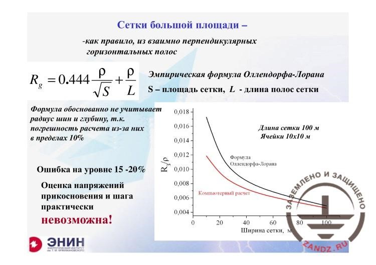
Grids of large areas
| Сетки большой площади - | Grids of large areas |
| - как правило, из взаимно перпендикулярных горизонтальных полос | are usually made of orthogonally related horizontal bands |
| Эмпирическая формула Оллендорфа-Лорана | Empirical Ollendorff — Laurent formula |
| S – площадь сетки, L – длина полос сетки | S is the grid area, L is the grid band length |
| Формула обоснованно не учитывает радиус шин и глубину, т.к. погрешность расчета из-за них в пределах 10% | The formula reasonably does not consider the bus radius and depth, since the calculation error is within 10% |
| Ошибка на уровне 15-20% | Error is about 15–20% |
| Оценка напряжений прикосновения и шага практически невозможна! | Evaluation of the touch and step voltages is almost impossible! |
| Длина сетки 100 м | Grid length is 100 m |
| Ячейки 10х10 м | Cells of 10 x 10 m |
| Формула Оллендорфа-Лорана | Ollendorff — Laurent formula |
| Компьютерный расчет | Computer calculations |
| Ширина сетки, м | Grid width, m |
– I do not know how to deal with them in real conditions. Now, what can we do next? How to calculate such earthing circuits? And due to the fact that the earthing circuit of any substation is generally a grid, then the Ollendorff — Laurent formula provided above and three seminars ago yields a very good approximation to the real-life situation. Here is a graph with two curves. The black curve is the calculation of the earthing resistance of the substation, the resistance of earthing circuits of 100 meters long with the 10 m cells, depending on the width. And the lower, red curve is the calculation performed in the strict computer application. As you can see, the difference between these two curves (now, the arrow has appeared, everything is fine), the difference between these curves is not very significant. And in the engineering calculations, the Laurent formula may be used. There will be an error of about 15–20% that is not critical because the Laurent formula provides a greater resistance than it really is. And if you use it, you will have some reserves.
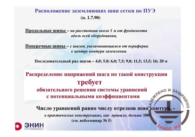
Arrangement of grid earthing buses according to the EIC
| Расположение заземляющих шин сетки по ПУЭ (п. 1.7.90) | Arrangement of grid earthing buses according to the EIC (item 1.7.90) |
| Продольные шины – на расстоянии около 1 м от фундамента вдоль осей оборудования, | Lengthway buses are at the distance of about 1 m from the foundation along the equipment’s axes, |
| Поперечный шины – с шагом, увеличивающимся от периферии к центру контура заземления. | Lateral buses are with the step increasing from the periphery to the earthing circuit’s center. |
| Последовательный ряд шагов – 4,0; 5,0; 6,0; 7,5; 9,0; 11,5; 13,5; 16; 20 м | Sequential step series: 4.0, 5.0, 6.0, 7.5, 9.0, 11.5, 13.5, 16, 20 m |
| Распределение напряжений шага по такой конструкции требует обязательного решения системы уравнений с потенциальными коэффициентами | Distribution of step voltages in such structure requires the solution of the system of equations with the potential ratios |
| Число уравнений равно числу отрезков шин контура, - | The number of equations is equal to the number of sections of the circuit buses, - |
| В практических конструкциях, как правило, больше 100! | in real structures, it is usually more than 100! |
| (см. вебсеминар № 5) | (see webinar No. 5) |
– How does the EIC require to spread this grid? The grid is required to be spread as follows. The lengthway buses must be located at the distance of 1 m from the foundation of the equipment that is located on the open distribution device. And the lateral buses must be located with the varying step from about 4 m from the edge to 20 m in the middle of the grid. It is made to equalize the touch voltage. But you will not be able to calculate the touch voltages according to the Laurent formula. We need a computer calculation for this. You cannot think of anything else except for computer calculations. And when my colleagues handed these questions over to me, there was a comment in the brackets for this question, “calculation without using the computer”. So, dear colleagues, you cannot make any modern calculations without a computer. This is related to a simple thing. We had a seminar where we learned how to calculate the earthing resistance and the potentials distribution across the substation territory. We studied this in details. The equations are generated. Everything can be recorded. But there are as many equations as the number of elements in the substation's grid.
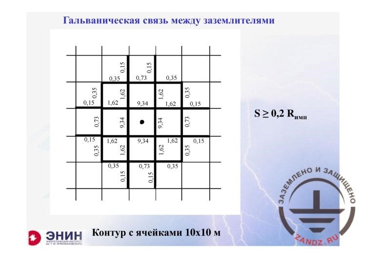
Galvanic coupling between earthing devices
| Гальваническая связь между заземлителями | Galvanic coupling between earthing devices |
| Контур с ячейками 10х10 м | Circuit with the cells of 10 x 10 m |
– We have one more question. It is very important. The issue of galvanic coupling between the earthing devices. When the substation earthing resistance is made, e.g., the following thing is written there. So, for example, it is written there that if you are using the lightning arresters, and the lightning arresters are installed on portal frames, and the portal frame is 15 meters from, e.g., a power transformer, in this case, you must not install the lightning arrester on it. You have to install a standalone lightning arrester and provide special earthing devices for it. I have drawn a piece of the substation grid here. And this point is where the earthing device of the lightning arrester is placed, which, based on the distance to the grid, may be considered a standalone device according to all EIC requirements. Why did they provide for a standalone earthing device? It was made to achieve that the lightning current would not enter the earthing device associated, for example, with the neutral wire of the substation's transformer. And now look at the actual situation. The values shown on all of these elements are percents of the lightning current that gets into the given element. And it turns out that about 40% of the current get into 4 elements of the nearest substation buses, the earthing circuit of the substation. What have I achieved by installing this standalone lightning arrester? Almost nothing. If I calculate the lightning current fraction that gets into the substation, it is more than 60% here. You may ensure this EIC requirement in paper, but it looks like you cannot do that in real life.
– Eduard Meerovich, we have a question regarding the protection of high-voltage facilities. You have proceeded to the next question as I can see.
– What is the question?
– Regarding the materials that may be used in the substation. Let me read the question in full.
– Read it to me.
– Question from Alexander Anufriev. Hello, Eduard Meerovich! We are operating a high-voltage line and a 110 and 500 kV substation, the FGC UES facility. The question related to the material used for an earthing device and earthing conductors in the electrical installations for more than 1,000 V. The requirements to the conductor materials are defined in the EIC, Technical Bulletin No. 11/206, and the instructions for the development of earthing grids and lightning protection. Thus, these documents allow the use of carbon steel. In 2012, FGC issued the guidelines that also allow for the use of carbon steel. But since 2015, GOST for the low-voltage installation, part 5.54, has been put into effect that does not provide the use of carbon steel as a material for earthing devices and earthing conductors. Can we refer to this GOST when choosing materials for the earthing devices of the electrical installations for over 1,000V?
– You know what? I can only answer this question as follows. The document hierarchy exists. According to it, the regulatory documents that cover all economy of our country take precedence over GOST. It means that such documents include instructions SO 153 34 21 122 that state that it is allowed to use carbon steel for the earthing devices and that it is also allowed to use non-ferrous metals, such as copper. The only thing you cannot use is aluminum that corrodes quickly in the earth. I think the situation is like this. Generally, in my agency, I can make any requirements stricter. And I may, for example, prohibit using carbon steel in my agency if I am its head. This is the agency's problem. I do not understand well if it makes any sense because you have not written this. And frankly, I do not know this document issued in 2005. What is permitted to use there? If it permits using a zinc-coated carbon steel, then there are numerous disputes regarding this in the high-voltage world. Because many considerations and experiments show that zinc-coated steel functions excellently if there is no other carbon steel around it. And if there is a zinc-coated steel and a carbon steel is near it; and it is always present in the distribution device because it is in the reinforced concrete supports of foundations in the form of reinforcement rods; in this case, zinc exists for a short period, about 2–3 years, on average.
– More questions from this author. One second. What regulatory document requires attaching the internal fencing of the electrical installation of over 1,000 V to the earthing device of this electrical installation?
– The issue of fencing is clearly defined in the EIC. There is a special section that describes all aspects related to fencing. And you cannot think of anything else. The EIC should be clearly followed in this case.
– One more question from Alexander. Is it allowed to install a band earthing device flatwise rather than edgewise in the earth?
– And who said that you need to install it edgewise? I hear this for the first time. It is not prohibited to install it in the soil. The earthing resistance will not change from this.
– And there is also a question from Ramil Smirnov regarding high-voltage facilities. Question: how can we correctly make earthing of the fire-extinguishing equipment at a 110, 220 kV substation? As a separate circuit inside the substation or we should connect the earthing device to the common circuit?
– I do not know for what reason we should earth the fire-extinguishing equipment using a separate circuit. I cannot see any logic in this. But I know that the EIC states that in all cases except for the exceptional ones (please accept my apologies for tautologies), all the earthing circuits should be integrated into a common earthing circuit. I believe that this relates to the fire safety equipment in full.
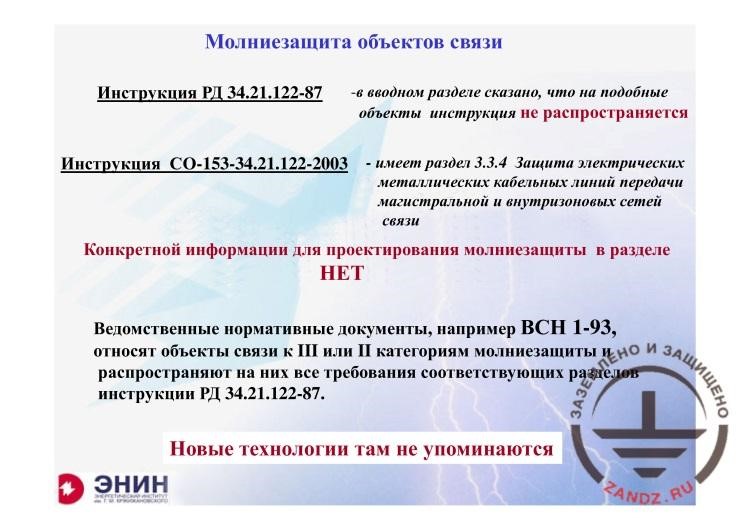
Lightning protection of communication facilities
| Молниезащита объектов связи | Lightning protection of communication facilities |
| Инструкция РД 34.21.122-87 | Instruction RD 34.21.122-87 |
| - в вводном разделе сказано, что на подобные объекты инструкция не распространяется | - in the introduction, it says that such facilities are not covered by the instruction |
| Инструкция СО-153-34.21.122-2003 | Instruction SO-153-34.21.122-2003 |
| - имеет раздел 3.3.4 Защита электрических металлических кабельных линий передачи магистральной и внутризоновых сетей связи | - contains Section 3.3.4 Protection of electrical metal cable transfer lines for trunk and intra zone communication networks |
| Конкретной информации для проектирования молниезащиты в разделе НЕТ | NO particular information for designing lightning protection in section |
| Ведомственные нормативные документы, например ВСН 1-93, относят объекты связи к III или II категориям молниезащиты и распространяют на них все требования соответствующих разделов инструкции РД 34.21.122-87. | Regulatory documents of the agencies, for example, VSN 1-93, refer to the communication facilities of Category III and II in terms of lightning protection and apply all requirements of the respective sections in instruction RD 34.21.122-87. |
| Новые технологии там не упоминаются | New technologies are not mentioned there |
– Now, I have opened the slide and I do not know what to do with it. You know, I cannot imagine how to provide the lightning protection of the communication facilities. The point is the following. Instructions RD 34 state clearly that the document does not cover the communication facilities at all. Instructions SO 153-34 contain Section 3.3.4 Protection of electrical metal cable lines for trunk and intra territorial communication networks. I have read this regulatory section and have not obtained any information from it, but only the empty words. Then I started searching for any other documents. I am sorry. I did that like an amateur. I say in advance that I am not a communication engineer. I looked at the documents we have for the lightning protection of the communication facilities. And I have found VSN 1-93. What does it say? It contains a fully reproduced RD 34 in terms of lightning protection of the facilities of the third and second categories. Everything that is contained in RD 34 was also used in this VSN. And I did not find any new technologies in it.
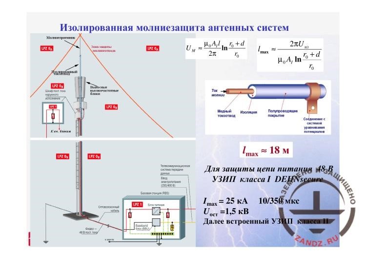
Isolated lightning protection of antenna systems
| Изолированная молниезащита антенных систем | Isolated lightning protection of antenna systems |
| Молниеприемник | Lightning arrester |
| Изолированный токоотвод | Isolated current collector |
| Зона защиты молниеотвода | Lightning arrester’s protection zone |
| Выносные высокочастотные блоки | External high-frequency units |
| Шкаф пост. Тока наружного исполнения | External direct current cabinet |
| Оптоволоконный кабель | Fiber optic cable |
| Базовая станция (RBS) | Base station (RBS) |
| Телекоммуникационная система передачи данных | Telecommunication data transfer system |
| Ввод | Input |
| Ток молнии | Lightning current |
| Медный токоотвод | Copper current collector |
| Изоляция | Insulation |
| Полупроводящее покрытие | Semiconductive coating |
| Соединение с системой уравнивания потенциалов | Connection to the potential equalizing system |
| Connection to the potential equalizing system | To protect 48 V power circuits |
| УЗИП класса I DEHNsecure | DEHNsecure Class I SDPs |
| кА | kA |
| 10/350 мкс | 10/350 mcs |
| кВ | kV |
| Далее встроенный УЗИП класса II | Then the embedded Class II SDP |
– But I know that innovative technologies are available. And I know that the innovative technologies primarily refer to the antenna systems, which are today largely installed by the communication engineers to provide mobile phone communications. The issue of installing these antennas was seriously elaborated in Europe but not in Russia. And I admit that everything that is shown in this slide was taken from the guidelines of a German company DEHN + SOHNE that makes advertising for the lightning protection device for the antenna systems, which is called the isolated lightning protection. That is what I am talking about. The point is that the lightning arrester of this antenna system has to be completely isolated from the electronic devices that provide the communication service. And generally, it is also isolated from the power source that powers this antenna and the building whereon the antenna is installed. Because it is a very painful question for the building’s owners: what will happen to the electronics and the energy equipment connected with the building when an antenna is installed on my building? This issue is solved as follows. The entire system for draining the lightning current that got into the lightning arrester is made through a specially isolated cable with a semiconductor coating that significantly increases the voltage of the breakover in the cable insulation. And this is a painful issue. As a result of using high technologies, today we can drain the lightning current from the lightning arrester for 18 meters but not any further. It is because the interference covers the electrical strength of this cable insulation. But 18 meters are generally enough to drain the lightning current into the earthing device of the building.
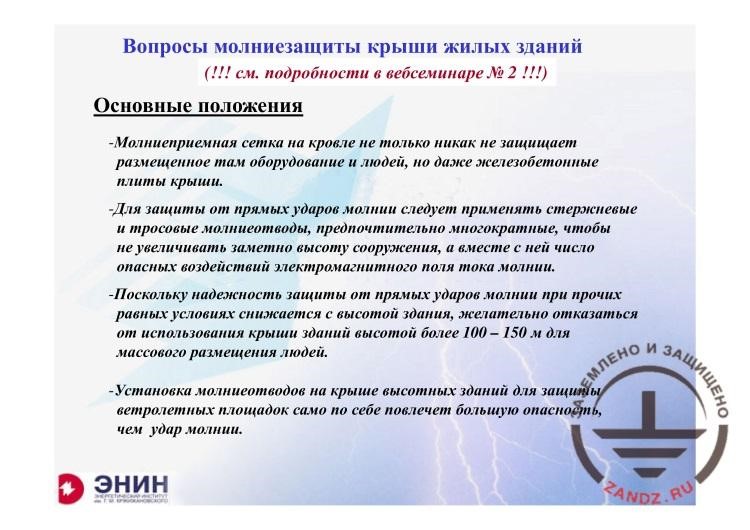
Lightning protection issues for residential buildings
| Вопросы молниезащиты крыши жилых зданий | Lightning protection issues for the roofs of residential buildings |
| (!!! См. подробности в вебсеминаре № 2!!!) | (!!! See details in webinar No. 2!!!) |
| Основные положения | Basic provisions |
| - Молниеприемная сетка на кровле не только никак не защищает размещенное там оборудование и людей, но даже железобетонные плиты крыши. | - The lightning protection grid on the roof does not protect the equipment and people located there as well as the reinforced concrete plates. |
| - Для защиты от прямых ударов молнии следует применять стержневые и тросовые молниеотводы, предпочтительно многократные, чтобы не увеличивать заметно высоту сооружения, а вместе с ней число опасных воздействий электромагнитного поля тока молнии. | - To protect against the direct lightning strikes, you have to use the lightning rod and wire, preferably multiple, so that not to increase significantly the structure’s height and the number of dangerous impacts of the electromagnetic field of the lightning current. |
| - Поскольку надежность защиты от прямых ударов молнии при прочих равных условиях снижается с высотой здания, желательно отказаться от использования крыши зданий высотой более 100-150 м для массового размещения людей. | - Since the protection reliability against the direct lightning strike, with other conditions being equal, is reduced with the building’s height, it is desired to refuse to use the roof of the building of over 100–150 meters for mass staying of people. |
| - Установка молниеотводов на крыше высотных зданий для защиты вертолетных площадок само по себе повлечет большую опасность, чем удар молнии. | - Installation of lightning arresters on the roof of the high-rise buildings to protect the helipads means a greater danger than the lightning strike. |
– Now, about the roofs of the residential buildings. We looked into this issue during the seminar. We studied these issues in the second webinar. And when I prepared for the current event, I looked through the materials of the seminar and became sure that generally no stupid things were said then. What were we talking about? When the modern coating of the residential building can be used as a lightning arrester. The answer in our regulatory documents was as follows. In any case when the coating has a metal thickness of not less than 0.5 mm. It does not matter whether an insulating layer is present on this coating having a thickness of up to 1 millimeter. In any case, even with such insulation or if the paint is present, we can use this device as a lightning arrester. It means that you can use metal tiles or Russian metal profiles as the lightning arresters. What reservation may be made? We also discussed that. And the reservation is as follows. The roof structure must not have any flammable items. But it will be a strain for our designer. Why? It is because in many buildings, especially in individual houses, the roof-sheathing and the framework are made of wood. And according to the fire safety experts, treating them with fire-safe compounds does not make them non-flammable.
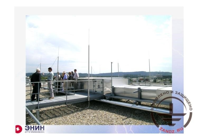
Using a lightning protection grid and low-height multiple lightning arresters on the roof
– We were talking about that the use of the grid that is installed on the roof does not provide anything at all. That we have to elevate the grid above the roof to protect the devices or even people if they are present on the roof as shown here, if it is used as an observation site. In this case, we have to either hang closed wire lightning arresters above the roof as discussed or install a system of lightning rods with a small height. With the height of about 3 meters, which are installed with the step of not more than 10 meters from each other. It is almost the same as shown in this photo I made in Germany.
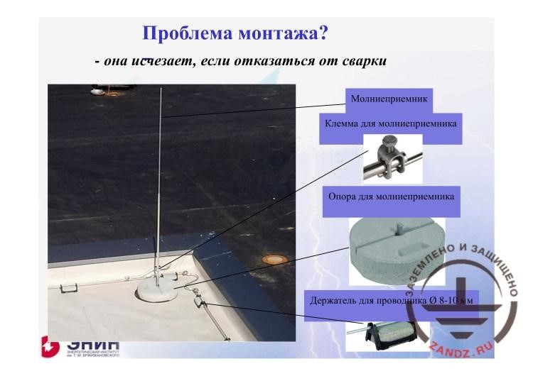
Issues of lightning protection installation
| Проблема монтажа? | Installation issue? |
| - она исчезает, если отказаться от сварки | - it does not exist if you avoid welding |
| Молниеприемник | Lightning arrester |
| Клемма для молниеприемника | Terminal for the lightning arrester |
| Опора для молниеприемника | Support for the lightning arrester |
| Держатель для проводника диам. 8-10 мм | Holder for a conductor having a diameter of 8–10 mm |
– What question arises in this case? It is the following question. If I have to install many lightning arrestors using welding as specified in the Russian regulatory documents, I will have a problem. And the system of the lightning arrester installation that is offered and widely used in Europe is as follows: a metal base is installed. This base is made of metal, and concrete slugs are laid on this metal base to provide more weight, and then the lightning arrester is installed into the tube of such base and is screwed with bolts. And these bolt connections in Europe provide a transient resistance of not more than 0.003 Ohm! And due to the fact that 0.05 is allowed in Russia, such connections may be used to protect the roof by installing many of such lightning arresters.
They are installed here, can you see them? It takes about 5 minutes to install such lightning arrester. What is its advantage? If I need 5 minutes to install it, then I also need 5 minutes to de-install it. And we should de-install it because it is Russia here, and we have hard winters with lots of snow. The snow must be cleared off but the lightning arresters do not let me do this. So, if I install them for winter, then I will be able to clear the snow off without any problem.
This is probably the major issue that exists in the area of protection for residential buildings.
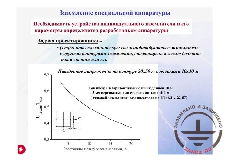
Earthing of special equipment
| Заземление специальной аппаратуры | Earthing of special equipment |
| Необходимость устройства индивидуального заземлителя и его параметры определяются разработчиком аппаратуры | The need to create an individual earthing device and its parameters are defined by the equipment’s manufacturer |
| Задача проектировщика - | The task of the designer - |
| - устранить гальваническую связь индивидуального заземлителя с другими контурами заземления, отводящими в землю большие токи молнии или к.з. | - to eliminate the galvanic coupling of an individual earthing device with other earthing circuits draining large lightning currents or short circuit to the earth |
| Наведенное напряжение на контуре 50х50 м с ячейками 10х10 м | Induced voltage in the circuit of 50 x 50 m with the cells of 10 x 10 m |
| Uпассив. | Upass. |
| Iмол. | Ilightning |
| Расстояние между заземлителями, м | Distance between earthing devices, m |
| Ток введен в горизонтальную шину длиной 10 м с 3-мя вертикальными стержнями длиной 3 м (типовой заземлитель молниеотвода по РД 34.21.122-87) | The current is introduced into the horizontal bus with the length of 10 m with 3 vertical rods of 3 m long (typical earthing device of the lightning arrester according to RD 34.21.122-87) |
– When you proceed to the next question, we will have a break, because the questions regarding the earthing of various high-voltage facilities and substations are still being received.
– Let's do the following thing. I will try to finish in about 10 minutes. And you collect these questions.
– OK, let's do it.
– Because there is only one question left. It is about the earthing of special equipment. I cannot say anything about the earthing of special equipment. What kind of earthing is required for the special equipment? Whether it is a medical imaging unit or some ultra-sensitive equipment, I just do not know. The equipment manufacturer must know this. But my or your (as the designers) aim is to provide this. What is the major point here? It is the following. At what distance from the earthing device of the lightning arrester should we install the individual earthing device so that low acceptable voltage and acceptable current would go there. The designer must be able to solve these issues. And he can only do that in a single way, by using computer applications.
<< Previous page
slides from 1 to 9
Next page >>
slides from 19 to 25 + Questions and answers
Related Articles:

 Webinar titled "Answers to Your Questions Regarding Earthing and Lightning Protection" Page 1
 Webinar titled "Answers to Your Questions Regarding Earthing and Lightning Protection". Page 3