The ninth webinar of "Earthing and Lightning Protection: Design Issues and Problems" series
Webinar text. Page 3
Fast navigation by slides:
<< Page 1:
1. Answer to your questions
2. Reinforced concrete foundation as an earthing device
3. Considering a double-layer soil according to GOST 12.1.030-81
4. Protection of substation against direct lightning strikes
5. Grid efficiency
6. What are the wire advantages?
7. Multi-wire lightning protection for the open distribution devices' substations
8. Using sandwich panels for raining the lightning current
9. Design of earthing and lightning protection for 110–330 kV substations
<< Page 2:
10. Grids of large areas
11. Arrangement of grid earthing buses according to the EIC
12. Galvanic coupling between earthing devices
13. Lightning protection of communication facilities
14. Isolated lightning protection of antenna systems
15. Lightning protection issues for residential buildings
16. Using a lightning protection grid
17. Issues of lightning protection installation
18. Earthing of special equipment
Page 3:
19. Induced current in the 50 x 50 m circuit with the 10 x 10 m cells
20. Calculation of magnetic current of a lightning
21. How to determine currents in current collectors?
22. Effect of multiple current collectors
23. Potential equalizing: primary and secondary
24. Features of designing earthing devices for facilities
25. Questions and answers
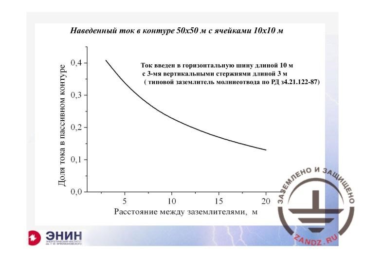
Induced current in the 50 x 50 m circuit with the 10 x 10 m cells
| Наведенный ток в контуре 50х50 м с ячейками 10х10 м | Induced current in the 50 x 50 m circuit with the 10 x 10 m cells |
| Доля тока в с | Current fraction in a passive circuit |
| Расстояние между заземлителями, м | Distance between earthing devices, m |
| Ток введен в горизонтальную шину длиной 10 м с 3-мя вертикальными стержнями длиной 3 м (типовой заземлитель молниеотвода по РД 34.21.122-87) | The current is introduced into the horizontal bus with the length of 10 m with 3 vertical rods of 3 m long (a typical earthing device of the lightning arrester according to RD 34.21.122-87) |
– For example, it is shown here how the fraction of a lightning current depends on the distance between the earthing devices, the special and typical earthing devices. Depending on the distance, you can see that 10–15 meters do not prevent from large current getting into the earthing device of special equipment. What can we do with the earthing device of special equipment, if it is really needed? I think that the most correct although expensive solution is to use an earth rod. But what earth rod should be used? It is the following earth rod. A well for a depth of about 20–30 meters is dug and the cable of the earthing device isolated from the earth is lowered there. Only its lower end is free of insulation and only the lower end contacts the soil. If you make such earthing device and choose the correct insulation designed for the actual voltage, such individual earthing device may be really made. I think that, in the urban area, since such special devices are primarily used in hospitals, for example, the medical imaging unit, are installed in the urban areas. But I think there is nothing else you can do.
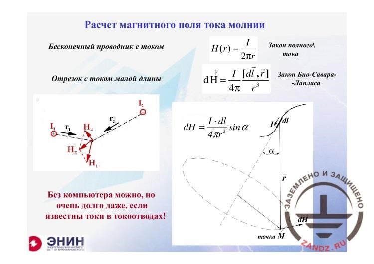
Calculation of magnetic current of a lightning
| Расчет магнитного поля тока молнии | Calculation of magnetic current of a lightning |
| Бесконечный проводник с током | Infinitely long conductor with the current |
| Закон полного тока | Ampere’s circuital law |
| Отрезок с током малой длины | Small section with the current |
| Закон Био-Савара-Лапласа | Biot – Savart — Laplace |
| Без компьютера можно, но очень долго даже, если известны токи в токоотводах! | It is possible without a computer but it takes much time even if we know the currents in current collectors! |
| Точка М | Point M |
– And the final question I would like to answer is how to calculate the magnetic field of the lightning current. The point is that there is nothing you can use except for the Biot — Savart law. Any conductor with the current is divided into sections of small lengths, which are significantly shorter than the distance to the point wherein the field is defined. Compose an expression according to the Biot — Savart law for the magnetic field strength, and make a vector summation for these sections, as it is shown. The task is very simple in terms of technology. But due to the fact that the real structure may have hundreds or even thousands of such sections, you will not be able to solve this task without a computer. And all of these tasks, when we have to solve them during the design calculations, are performed this way. And there is nothing else I can offer.
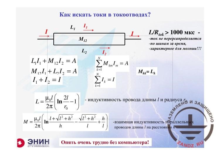
How to determine currents in current collectors?
| Как искать токи в токоотводах? | How to determine currents in current collectors? |
| - ток не перераспределяется - по шинам за время, - характерное для молнии!!! |
- the current is not redistributed - in the buses for the time - typical for the lightning!!! |
| - индуктивность провода длины l и радиуса r | - inductance of a wire with length l and radius r |
| - взаимная индуктивность параллельных проводов длины l на расстоянии h | - mutual inductance of parallel wires with length l at the distance h |
| Опять очень трудно без компьютера! | Again, it is very difficult without a computer! |
– And one more point. You have to do the same thing to calculate how the currents flow in the earthing device. You have to generate an equation for magnetic fluxes, solve this system of equations, but due to the fact that you have, for example, twenty, thirty, forty earthing devices or current collectors, you will have to solve the system of equations with 20, 30, 40, 50 indeterminates, and do it another way. It is also impossible without the computer application. But the solution is very simple. This is a solution of the standard linear algebraic equations, but there are many of them and, therefore, you can only solve them using a large matrix. If someone needs it, then the only way you have is to use the computer.
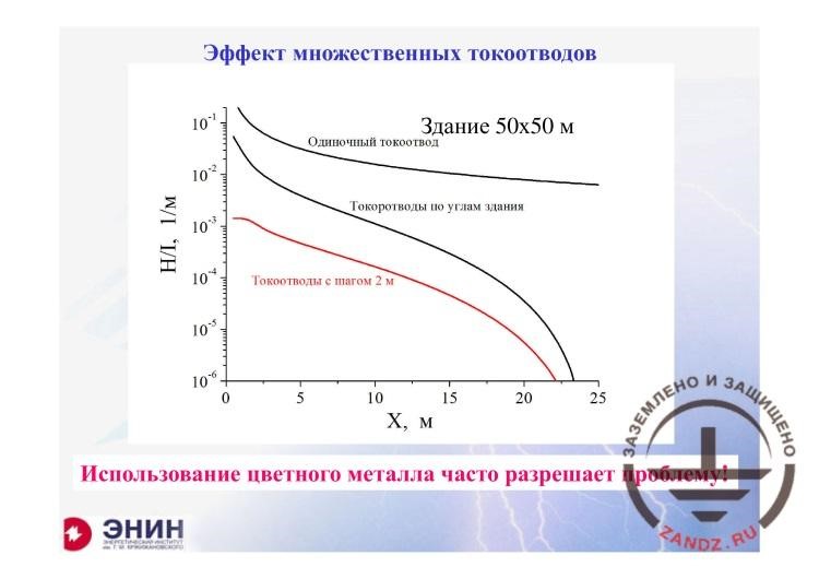
Effect of multiple current collectors
| Эффект множественных токоотводов | Effect of multiple current collectors |
| Здание 50х50 м | Building of 50 x 50 m |
| Одиночный токоотвод | Single current collectors |
| Токоотводы по углам здания | Current collectors in the building corners |
| Токоотводы с шагом 2 м | Current collectors with the step of 2 m |
| м | m |
| Использование цветного металла часто разрешает проблему! | The use of non-ferrous metal often solves the problem! |
– I tell you once more that it is very beneficial to use large number of current collectors. If you distribute the lightning current among the large number of current collectors, you will rapidly decrease the magnetic field inside this administrative or industrial building. As a result, you can decrease the electromagnetic interference significantly. I have taken the building of 50 x 50 meters, it is an industrial building. A current flows along a single current collector. And there is the current running along the current collectors that are spaced in 2 meters. The difference between these values here, at the edge, near the current collectors is 100 times, and here it is about 10,000 times. How can we make the current collectors spaced in 2 meters? It is an absurd to install them. And you should not do that. If you have an industrial or administrative building, the walls of such building will be probably formed by glass units. And if these are the glass units, then they have the duraluminum reinforcement. And the cross-section of the duraluminum reinforcement is suitable for draining the lightning current. If you interconnect these glass units, and they are connected automatically because they are installed on the embedded fixtures of the intermediate floors during the construction and are secured with bolt connections. If you make all of these, you will obtain a current collector system. The current collector system that will be able to drain the lightning current to the earth in many ways. And such lightning current draining in many ways is the logarithmic scale; it leads to the following. This is immediately at the current collectors, and this is nearer to the building center. This effect is very common and useful. But in order to widely and usefully apply it, we need to know how to calculate the current distribution among the current collectors. You can surely do that using a computer. And if you need a rough estimate, I think that you will not make a serious mistake, if you do not use the computer, but calculate the number of current collectors, divide the lightning current by this number, and obtain the error of not more than 25%. And you will say then that each current collector contains a particular current. Now, a magnetic flux is created from each current collector, which is defined by the current divided by 2 pi x r, and sum these values as vectors using the rule of the right corkscrew. But if you have enough patience to sum up 20 vectors, I assure you that you can go without any computer.
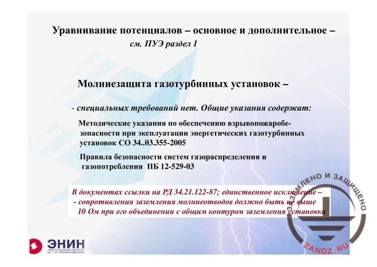
Potential equalizing: primary and secondary
| Уравнивание потенциалов – основное и дополнительное - | Potential equalizing: primary and secondary |
| См. ПУЗ раздел 1 | See the EIC, Section 1 |
| Молниезащита газотурбинных установок - | Lightning protection for the gas turbine units - |
| - специальных требований нет. Общие указания содержат: | - no special requirements. General directions contain: |
| Методические указания по обеспечению взрывопожаробезопасности при эксплуатации энергетических газотурбинных установок СО 34.03.355-2005 | Methodical guidelines to provide explosion and fire safety in operation of power gas turbine units, SO 34.03.355-2005 |
| Правила безопасности систем газораспределения и газопотребления ПБ 12-529-03 | Safety rules for the gas distribution and consumption systems, PB 12-529-03 |
| В документах ссылки на РД 34.21.122-87; единственное исключение – сопротивления заземления молниеотводов должно быть не выше 10 Ом при его объединении с общим контуром заземления установки | Documents contain references to RD 34.21.122-87; the only exception is that the earthing resistance of the lightning arresters should not exceed 10 Ohm upon its combining with the general earthing circuit of the installation |
– There is a question remained about the potential equalizing. You know that I cannot add anything else to Chapter 1 of the EIC. It describes everything in details. And I also had one specific question about the lightning protection of the gas turbine units. I could find no special requirements to the lightning protection of the gas turbine units. If it is an external installation, you have to protect it as a conventional external installation. If it is inside the building, then it is the lightning protection of the building. The "Gazprom" standard does not set any special requirements for this. And there are also no all-Russian standards. There is such unit, a rule for the safety of the systems for gas distribution, gas consumption, but in this document, there is generally nothing new compared to RD 34 except for only one requirement. The requirement is that the requirements to earthing of the lightning arresters are made stricter. Therein, instead of the typical earthing devices, which are described in RD 34, you should have the earthing resistance of not more than 10 Ohm. And if the soil resistivity is more than 500 Ohm m, then you can increase the earthing resistance by the empirical formulas provided in this document. They generally allow increasing such resistance roughly 2 times. That is all I can say about this. Nadezhda, do we have any questions?
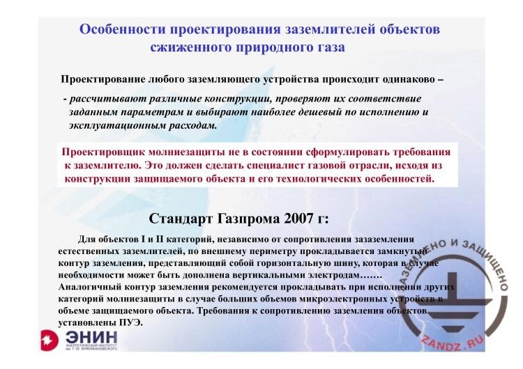
Features of designing earthing devices for the facilities
| Особенности проектирования заземлителей объектов сжиженного природного газа | Features of designing earthing devices for the LNG facilities |
| Проектирование любого заземляющего устройства происходит одинаково - | Designing of any earthing device occurs similarly - |
| - рассчитывают различные конструкции, проверяют их соответствие заданным параметрам и выбирают наиболее дешевый по исполнению и эксплуатационным расходам. | - various structures are calculated, their compliance with the set parameters is verified, and the cheapest option in terms of design and operating costs is chosen. |
| Проектирование молниезащиты не в состоянии сформировать требования к заземлителю. Это должен сделать специалист газовой отрасли, исходя из конструкции защищаемого объекта и его технологических особенностей. | Design of the lightning protection cannot define the requirements to the earthing device. This must be done by a gas industry specialist based on the structure of the protected facility and its process features. |
| Стандарт Газпрома 2007 г: | “Gazprom” standard issued in 2007: |
| Для объектов I и II категорий, независимо от сопротивления заземления естественных заземлителей, по внешнему периметру прокладывается замкнутый контур заземления, представляющий собой горизонтальную шину, которая в случае необходимости может быть дополнена вертикальными электродами…… | For the Category I and II facilities, irrespective of the earthing resistance of the natural earthing devices, along the external perimeter, a closed earthing circuit is installed in the form of a horizontal bus that may be supplemented by the vertical electrodes, if it is necessary…… |
| Аналогичный контур заземления рекомендуется прокладывать при исполнении других категорий молниезащиты в случае больших объемов микроэлектронных устройств в объеме защищаемого объекта. Требования к сопротивлению заземления объектов установлены ПУЭ. | The similar earthing circuit is recommended when making other categories of lightning protection in case of large volumes of microelectronic devices within the protected facility. The requirements to the facility’s earthing resistance have been set in the EIC. |
Questions and answers
– Let's get back to the earthing of various electrical high-voltage installations (wait for one second, I will find it). The first question was from Vasily Krupko. He says that he is interested in the following: the resistance according to the EIC of the earthing device with an isolated neutral wire of the typical 10/0.4 substation must be 4 Ohm. Why does MOESK require 0.5 Ohm?
– What?
– MOESK requires 0.5 Ohm under these conditions. He asked why.
– The earthing resistance of installations with the isolated neutral wire?
– Yes.
– Oh, this. It is written in the EIC and nobody can ask you to violate the EIC. But I will repeat the following point. The EIC states the value that cannot be lower or, rather, higher. If, for some considerations, an agency imposes stricter requirements than the EIC, it can do this today. It is a different story how much it will cost for them. It may be very expensive. Probably, artificial earthing devices may be installed there, or probably the fill-up soil is required. But they have the right to require it. I repeat, any regulatory documents should be interpreted as follows. It is written there what items should be made mandatory. And if the owner wants it to be even more favorable, i.e., for example, 0.1 Ohm instead of 4 Ohm, he needs this for some reason. He wants to invest money there. He has the right to do it.
– OK, I got it. And the question from Grigory Zakharov. It is probably also about the electrical installation. Communication hardware is installed on the illumination mast in addition to spotlights. I think that the lightning arrester is also installed there. It is connected to its own earthing circuit through the mast directly. Can wire support brackets for feeder devices be used to lower them on the cable bridge if the insulators are used (metal coupling between the earthing circuits of a bridge and the mast is disrupted)?
– This is the question I cannot answer for the following reason. When the lightning arrester device is used today on the mast wherein some other utilities are laid, for example, electrical or communication. The universal solution that does not impose any requirements to the equipment is the solution associated with the isolated lightning arrester. It means that your lightning arrester must be isolated from the mast, and the current collector is isolated from all equipment and this current is taken to the place where it presents no danger. With such solution, you may stop thinking about anything and install generally any electronics on the mast. But if you do not do this, then you have to think of what interference requirements are imposed by the manufacturer of the equipment to be installed. I do not know these requirements. And you will not be able to describe them to me. Therefore, such design should be developed on an individual basis. That is why I have provided an example with antenna. This example is a medication that is suitable for all cases. You can use it without any doubts. And if you do not want to use it, do it another way. You have to calculate the interference at the equipment input and ask the equipment’s manufacturer whether it is fine for them. If it is not, then the next step is to try to select the SDPs using which you will protect the equipment.
– Now, one more question regarding the open distribution devices. It is often that during the examination of earthing devices in the substation for open distribution devices for 35, 110, 220, 500 kV, significant flowing occurs in the metal cable trays having the metal coupling between the metal supports of the equipment as well as complete distribution devices of external installation and open distribution devices but not in the earthing devices. Farid asks if it is suitable and what can you recommend to reduce current spreading?
– This is a good question. It is very good. Thank you for the question because I am also interested in this question and I can provide an example. You can, if you know the substation earthing circuit, you have its full drawing, and you have drawings and arrangements of all cable trays you have. And in addition to the cable trays, there are also air ducts that supply compressed gas to the air switches, there is also oil pipeline and much equipment. If your hardware is documented on the substation layout, you may generally do the following thing. You can calculate where and in what amount your lightning current will go and you can do that. You can also do the following thing. You can contact a company that is capable of measuring where and to what circuit a particular current will go. I think that in Russia, the company of Ruslan Borisov, the "ELNAP" company does it... It is not an advertising, I just tell you what company you may contact. I have no ties with it but I have ordered this for myself when I had to perform such work in the territory of the car check point at the Finland border. We performed such work there and determined that a large portion of the lightning current may flow through the utilities. Up to dozens percent. Now, if you already know where and how the current flows, you will have the second question: how can you avoid this? If you have a system of underground utilities, you cannot avoid this. You cannot re-arrange the entire routing system on the substation to avoid such situation. But probably in some local cases you may move the cables, for example, from the earthing device of the lightning arrester, but sometimes it may be done in a more favorable situation. But generally you cannot avoid it. And the only thing you can do is to shield the cables that are placed inside the trays, install the SDPs for limiting voltages. Because re-routing is very expensive and troublesome. Although I know the individual cases when such re-routing was made.
– So, I think that everything that was associated with earthing of the high-voltage electrical installations. Then, questions for other subjects are provided, for example, for the grids. Gennady Goncharov asks if we can install the grid of less than 6 x 6 m, e.g., if the roof structure does not allow making it more than 5 x 5 m?
– You can even make a grid of 1 x 1 m. First, it is not prohibited because the dimensions of 12 x 12 m for the third category and 6 x 6 m for the second category are the minimum dimensions, the maximum dimensions, and the minimum dimensions can be any. But you also note that grids of 5 x 5 m, 6 x 6 m and even 1 x 1 m are equally low-efficient and they do not provide many benefits.
– And the question from Dmitry regarding the earth rod you mentioned in the previous answer. If the earthing device is an earth rod deepened, for example, to 1 m, you have to connect it with the isolated earthing device to provide more efficiency or with an open conductor?
– If it is only 1 m, it does not matter at all. Because 1 m means that the earthing device is essentially on the surface. And if you make an earth rod and you do not go deep from the earthing circuit of the substation, then you have to isolate it. And this isolated earthing that withstands the voltage that may be present between the top soil layers and the depth layer, it is certainly isolated here. And 1 m does not make any difference, it is the same as on the surface.
– Now, the question from Alexander Igorevich. He has a calculation for vertical and horizontal earthing devices, for each of them separately. How to calculate total resistance of the earthing device composed of vertical electrodes connected horizontally?
– The point is as follows. We had a special seminar during which we studied how to calculate the earthing devices. When you have an earthing device consisting of a set of vertical, horizontal, lengthway, lateral, or any other earthing devices, it is useless to know the earthing resistances for each of them individually. It is because in old recommendations, when the computers were not widely used, the following thing was done. They said: I have, for example, 10 rods. I know the earthing resistance of each of them. How can I determine their total earthing resistance? And they say: they work in parallel, and it means that the earthing resistance, if I have 10 similar rods, must be reduced 10-fold. But it will be incorrect. It is incorrect due to the fact that each earthing device, when the current flows, interferes with other devices. Therefore, you have to add a utilization ratio, an adjustment ratio that was provided in some tables. This way the guidelines that did not involve the computers were created. Today, a precise method for such calculations exists that is defined as follows. The potential of each element of an earthing device based on the influence of all currents, of all elements nearby. For each element, a system of equations is generated containing as many terms as many elements you have. And the number of equations will also be equal to the number of elements. If you solve such system, you will find the voltage of the entire system. And if the voltage is divided by the current, you will obtain the resistance.
– And now, we have an outstanding question. It refers to earthing of electrical installations in permafrost.
– You know, earthing of installations located in permafrost does not differ from earthing of installations specified in Section 1.7 of the EIC. So, depending on the soil resistivity, a simplifying adjustment is introduced that allows increasing the earthing resistance. Generally, that is all. Because there is nothing else can be in this case. But you may be concerned with the following question: why do you try to obtain the resistance of, for example, 0.5 Ohm in the black soil, while in permafrost you will use 10 Ohm? Although people and equipment will not benefit from it. And the second question is also here. But the EIC allows increasing the allowable earthing resistance, if it is a very high-ohmic soil. For example, if we mean the power lines, the power line supports, then the minimum allowable earthing resistance for a one-circuit support is 15 Ohm. And if you have an earthing resistance, if the soil resistivity increases up to 5,000 Ohm, then 30 Ohm are allowed. And if it is increased even more, and in the permafrost it increases even more, a formula is added that ties the particular resistivity with the allowable earthing resistance, and it is specified in the EIC in the chapter for earthing the power lines. An entire table is provided therein. And this table was shown during the seminar for earthing resistance.
– Then it turns out, dear participants, that you have a chance to ask something in the conclusion until we have new questions.
– I understand that it is difficult, especially for older people, to abandon the sliding ruler or even the scientific calculator. I understand that it is difficult. But today the industrial applications exist, such as MatLab, that allow solving the desired systems of equations. It is not so difficult to study this application. Young people come to work from the institute and they have probably studied such application. Today, the requirements to the equipment have changed so dramatically that you cannot avoid using a computer today. What to do? Break your habits. Sit down, take a simple textbook and study. I assure you that it is worth doing it.
– And it appears that today our participants have no more questions. I ask the participants to fill in... Just a minute, we have a question. Ramil Smirnov asks what to do if illumination and the CCTV equipment is installed on the fencing of a 110, 220 kV substation, which is not connected to the substation circuit. Thereby, a potential is taken to the fencing through the neutral conductors. Make isolation transformers or install an equalizing grid beyond the fencing at the depth of 1 m.
– You know, the point is that, probably, I cannot answer this question now because I have to look at what is achieved in this case. Let's agree upon the following. I am sure that we will have the next seminar. And we will ask Nadezhda to remind me that a person is waiting for such answer. There is also the next option. Send your question to e-mail and write your e-mail. I promise you that I will provide an answer within 10 days. But today I will not be able to answer your question.
– Dear participants. A link to the questionnaire will be sent to the chat. We ask you to fill it in. You may add the remaining questions and specify your desire regarding the event there.
– I thank all participants who stayed with us until the end of the seminar. And you know, I ask you to understand the following thing. There is no such specialist who could answer all questions for lightning protection. I am not this specialist. Therefore, probably someone who received my answers will be happy with it. You know what? It is impossible to answer several questions. You have to study each particular situation even if you are a very good specialist. Because there are no perfect specialists in lightning protection. Thank you again for your attention!
– Thanks to everyone, good luck and see you soon in the next event.
<< Previous page
slides from 10 to 18
Related Articles:

 Webinar titled "Answers to Your Questions Regarding Earthing and Lightning Protection" Page 1
 Webinar titled "Answers to Your Questions Regarding Earthing and Lightning Protection" Page 2