The system of surge arresters of class I should provide protection in cases of threats, caused by:
- lightning current flowing in the construction side in case of a direct discharge into the object,
- direct lightning strike or a strike near the overhead lines or low voltage cables in the ground,
- switching overvoltages, and also induced by an atmospheric charge,
Among objects, it which it is required or recommended to use arresters of class I in power supply, it is necessary to mention:
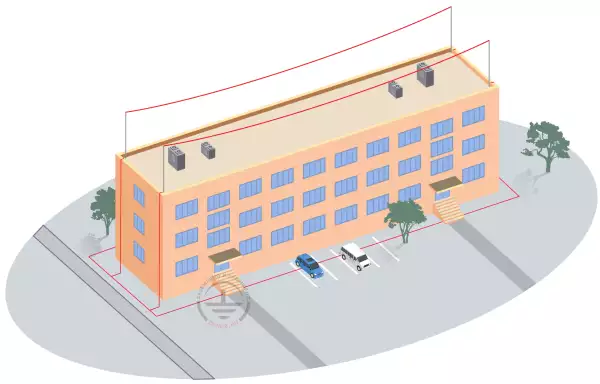
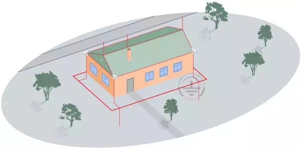
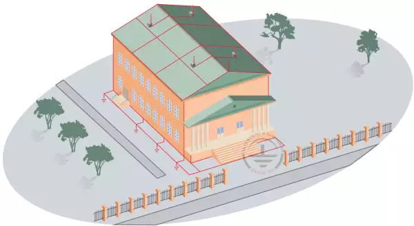
- Construction sites with lightning protection devices,
- objects without lightning protection , powered directly from overheadlines, or short cable inlets,
- objects without lightning protection, neighbouring with masts, towers, or constructions sites with lightning protection systems (there is a general ground electrode system in all cases).
Taking into account the recently wide-spread trend in plumbing equipment - overall change of metal water sewer conduit to plastic pipes - it it necessary to consider this equipment when analyzing lightning current spreading. When choosing arresters of class I for the project of sites protected with lightning protection system, it is necessary to consider the possibility of distribution of half of lightning current over their conductive paths.
Values of lightning currents, which may flow through the system of arresters depending on the required protection level are given in table 2. 1.
|
Protection level |
Reliability of lightning protection |
Current intensity, kA |
||||
| TN network system | TT* network system | TT** network system arresters | IT network system spark gap | IT network system |
||
| I | 98 % | ≥ 100/m | ≥ 100/m | ≥ 100 | ≥ 100/m | ≥ 100/m |
| II | 95% | ≥ 75/m | ≥ 75/m | ≥ 75 | ≥ 75/m | ≥ 75/m |
| III | 90% | ≥ 50/m | ≥ 50/m | ≥ 50 | ≥ 50/m | ≥ 50/m |
| IV | 80% | |||||
| m: means the number of conductors, where lightning current may flow for example, in system TN-S they are L1, L2, L3 N, and also PE - m = 5 *- system of 4 surge arresters, **- the so-called system 3+1 of three surge arresters and one spark gap |
||||||
Table 2.1. Vales of the current, which may flow
The system of surge arresters of class I should be installed behind the main safety device near the place of input of electric equipment into the construction site.
These places can be:
- connection of cables, or an additional safety cabinet near the connection,
- the main switchboard of low voltage.
Conductors, used for connecting arresters of class I, should be as short as possible. It is recommended to use of conductors not longer than 0,5 m for connecting class I arresters (fig.2.1).
Voltage drop on the inductance of conductors can be excluded, using the so-called "V-type connection" (fig. 2.1 b and fig. 2.2). Arresters used for this syste, should foresee the possibility of connecting two conductors to each contact (double clamps).
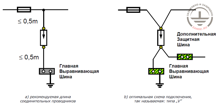
Fig. 2.1. Connection of class I arrester
Главная выравнивающая шина- main equalizing bus
Рекомендуемая длина соединительных проводников- recommended length of connecting leads
Дополнительная защитная шина – additional protective bus
Оптимальная схема подключения, так называемая: типа V - optimal connection scheme, the so-called “v” type
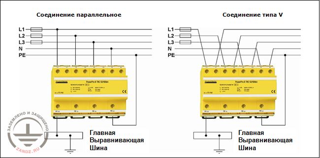
Fig.2.2. Example of parallel and sequential connection on the example of the protective module
Главная выравнивающая шина- main equalizing bus
Соединение параллельное- parallel connection
Соединение типа V – V-type connection
It is also possible to use conductors with cross section equal to the cross section of fuse conductors, which are located before the arresters. Voltage protection levels of class I arresters depend on their value and most frequently is lower than 4000 V (series: PowerPro BCD; IsoPro B), 2500 V (series: PowerPro BC, IsoPro BC) or even lower than 1000 V ( for example, series PowerPro BCD).
2.1. Surge arresters of class I
IEC 61643-1 regulation, containing technical requirements and test methods of surge arresters, doesn't force to use certain values of voltage protection level for this class arresters. It only gives recommended values, which in relation to the electric equipment of 230/400V in voltage, should be picked from the following range of values 600 V, 700 V, 800 V, 900 V, 1000 V, 1200 V, 1500 V, 1800 V, 2000 V, 2500 V, 3000 V, 4000 V, 5000 V и 6000 V.
In a multi-stage overvoltage suppression system, taking into consideration requirement of devices at the connection of equipment (table 2.1.), class I arresters should limit overvoltages to the level lower than the impact resistance of category IV- lower than 6000V.
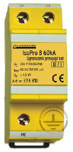
LEUTRON company, for example, offers class I arresters for the protection of devices and equipment: PowerPro B 50kA (FM), IsoPro B 60kA (FM), IsoPro B 25kA (FM) with voltage protection levels lower than 4000 V. Values of the main parameters of these arresters are shown in table 3.2.
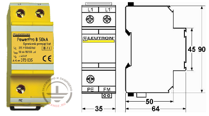
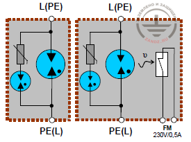
In the arrester of type PowerPro B 50kA (FM) (fig.2.3) a multi-exposive spark gap, placed in the atmosphere of neutral gas in a ceramic case, which provides:
- quicker response of the arrester if compared to arresters, containing classical spark gaps,
- voltage protection level lower than 4000 V,
- Possibility of protection from impact currents up to 50 kA 10/350 ms,
- marginal voltage distortion in the electric equipment, which occurrs after operation of the arrester,
- absense of gas emission outside the arrester.
| Table 2.2. Class I arresters with voltage protection level lower than 4000 V | ||||
|---|---|---|---|---|
| Arrester type | PowerPro B 50kA | IsoPro B 25kA | IsoPro B 60kA | |
| Static response voltage | Uagn | ≥ 800 В | 900 ± 20% | 900 ± 20% |
| Nominal operating voltage: 50/60 Hz | UN | 230/400 V | 230/400V | 230/400V |
| The greatest long-term operating voltage 50/60 Hz | Uc | 255 V | 255 | 255 |
| 100% response voltage at a lightning strike 1.2/50 ms | Uas | ≤ 4000 V | ≤ 4000 V | ≤ 4000 V |
| Voltage protection level | Up | ≤ 4000 V | ≤ 4000 V | ≤ 4000 V |
| Rated pulse current 10/350 ms | limp | 50 kA | 25 kA | 60 kA |
| Maximum preceding safety device | 250 A gL | 160 A gL | 160 A gL | |
| Insulation resistance | Risol | ≥ 1010 Оhm | ≥ 1010 Оhm | ≥ 1010 Оhm |
| Response time | tA | ≤ 50 ns | ≤ 50 ns | ≤ 50 ns |
| Operating temperature range | υ | -400...+850 | -400...+850 | -400...+850 |
| Level of protection, provided by the case | IP 20 | IP 20 | IP 20 | |
| Item number | LE-373-835 | LE-373-815 | LE-373-810 | |
| Assembly | On a bus of 35 mm | |||
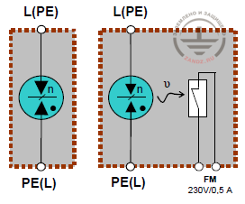
In the arresters of LEUTRON company there is a possibility to track the state of the spark gap. In case of temperature rise of the spark gap, a potentialless contact opens, which may be an element of the circuit, tracking the system of arresters. Arresters containing such tracking systems include an additional notion in their name FM.
Arresters of PowerPro series can be used in the so-called V connection (see fig.2.2).
 |
 |
|
| a) internal composition of arrester connections without and with tracking system of the spark gap | b) General view of the arrester, | c) main dimensions |
Fig.2.3. Arrester of class I PowerPro B 50 kA
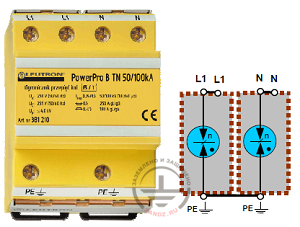
| PowerPro B TN 50/100 кА For one-phase network TN-S | |
 |
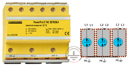 |
| PowerPro B TNS 50/100 кА for three-phase network TN-S | |
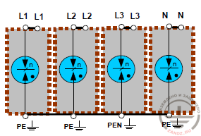 |
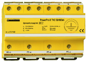 |
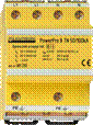
Fig.2.4. Examples of modular systems of arresters of series PowerPro B
 |
 |
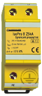 |
| IsoPro B 60kA | IsoPro B 25kA |
Fig.2.5. Arrester IsoPro: internal connection scheme without and with tracking of the state of the spark gap, and general view of arresters IsoPro B 60 кА and IsoPro B 25 кА
Interesting solution is also used in arresters IsoPro B 60kA (FM) and IsoPro B 25kA (FM). The system of parallely connected spark gaps with an additional voltage-variable resistor, sequentially connected with the spark gap in one branch, is placed in the case with the width of two typical modules (fig. 2.5).
In the offered system of connections, if pulse currents don't exceed 4 kA- for example at 10/350 (most frequent case of pulse occurrence in electric equipment), only a sequentially connected spark gap with the voltage-variable resistor functions. After the exceeding of the value of 4 kA by the pulse current, which happens in case of direct lightning strikes into the object or very near stikes, the main spark gap is additionally activated.
The main spark gap, used in the surge arrester IsoPro B 60 кА is able to protect from the impact of shock currents in the form of 10/350, and also current intensity up to 60 kA, and voltage protection level doesn't exceed the value of 4000V. In case of using IsoPro B 25kA the maximal shock current 10/350 can achieve the value of 25 kA, and voltage protection level 4000V.
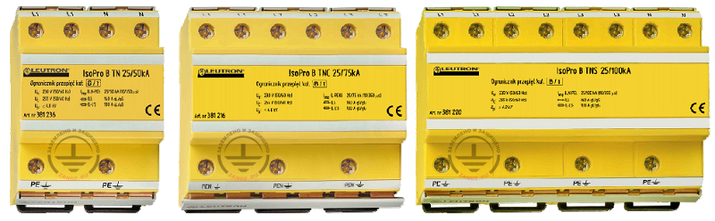
Similar to the case of PowerPro arresters, protective modules for the main network systems, created from surge arresters IsoPro are available (fig. 2.6).
| IsoPro B TN 25/50kA | IsoPro B TNC 25/75kA | IsoPro BC TNS 25/100kA |
 |
||
Fig.2.6. Examples of modular systems of arresters of series IsoPro B
Modular systems of arresters PowerPro and IsoPro can be parallely and sequentially connected. Exemplary solutions of these connections for the module PowerPro B TNS 50/100kA are shown on fig.3.2. Sequential connection can be carried out, if the value of fuse response current in electric equipment doesn't exceed 100 A.
Example of a parallel connection of the module PowerPro B TNS 50/100kA for the protected power system 230/400 V is shown in fig. 2.7.
Read before
"1.7. Schemes of surge arresters connection"
Read next
"2.2. Surge arresters of class I/II"
Related Articles:
 ZANDZ SMS-NEWSLETTER
 5. Reference book on basic parameters and types of surge arresters on the example of the LEUTRON element base