From the series of articles "Grounding in lightning protection - answers to frequently asked questions in the design".
This value can not be called suitable for environments where kiloampere lightning current is being spread. Specific resistivity even of highly conductive ground is about a billion times greater than the resistivity of conventional steel. At the arrangement of grounding, only a virtually unlimited amount of soil over which the current is distributed gets the professionals back.
Soil conductivity is extremely unstable. It strongly depends not only on its mineralogical composition, but also on humidity and temperature. That is why the guidelines have to give very approximate values of resistivity for different soils. The data from chart 1, taken from national guidelines, can be an example of that.
Chart 1
|
|
|
|
|
|
|
|
|
|
|
20-60 |
|
|
|
|
|
10-55 |
|
|
15-25 |
|
|
|
|
|
|
|
|
22500 |
In respect of the application, inhomogeneity of characteristics in soil depth is very important. It is firmly established by geological researches. It is not uncommon when under a thin (10 - 30 cm) layer of highly conductive soils with a resistivity below 100 ohm * m, there is a multimeter thick layer of rock, where the resistivity is greater than 104 Ohm * m. But an opposite picture is not unlikely, for example, due to an underground water flow at a depth of tens of meters under a layer of dry sand.
At what depth the soil should be gauged?
The specialists don't need to be reminded that the current from the grounding electrode goes into the ground "to infinity". Such a definition of the subject layer thickness is meaningless. The conductivity of the soil should be examined where it can still give a really significant contribution to the value of grounding resistance of the ground electrode system. At the simplest level, this task is simply solved for spherical or hemispherical electrodes. For example, for a hemispherical ground electrode in homogenous soil with the resistivity ρ1 the electric field intensity E(r), is determined by the current density σ(r) = I/(2πr2) from the equation, similar to Ohm's law E(r) = ρ1σ (r), allows to accurately calculate the voltage on the ground electrode by integrating E(r) from the surface of a hemisphere of radius r0 to infinity. This gives
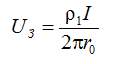
and that is why the exact value of grounding resistance is
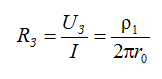
If to limit calculations on some explored depths of the soil h, the calculation will give a low value
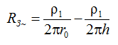
It is easily seen that the relative error will be δR3 = r0/ h. Therefore, to assess the grounding resistance with such an error in a uniform soil it is necessary to monitor the electric field to a depth
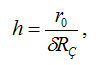
for example, within 20 h = m, where r0 = 1 m and the permissible relative error is taken to be 0.05.
Similar calculations for a two-layer environment (Fig. 1) will give
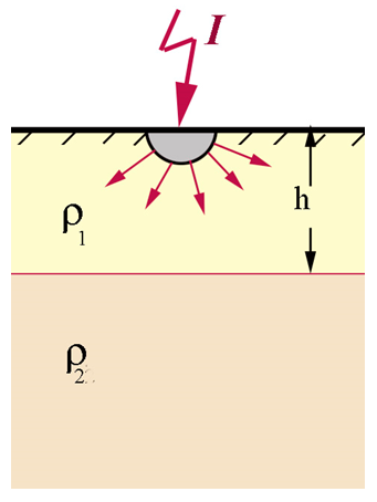
Figure 1
If to assume that the grounding resistivity changes its value from ρ1 to ρ2 at the depth h.
The assessment is of little use in practical terms, because hemispherical grounding applications did not find application. From the methodological standpoint it is interesting. Here the correlation of necessary depth of soil gauging and the size of the ground electrode, and the presence of structural changes in the ground, can be clearly observed.
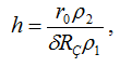
For practically significant electrodes, especially for their arbitrary combination, it is hard to perform analytical evaluations and thus, as already mentioned, it is necessary to resort to computer simulations. From the analysis above it follows that a quantitative description of a specific grounding device with specific dimensions should be entered into the computer model and it is necessary to provide calculation of its ground resistance, first in homogenous ground with resistivity ρ1 (Rρ1), and then in a two-layer environment (Rρ1-ρ2) at a different position of the boundary h, where the resistivity ρ changes abruptly from ρ1 to ρ2. The depth value h can be taken for an effective current penetration depth, if the difference between the calculated parameters Rρ1 and Rρ1-ρ2 does not exceed the permissible error, for example, 10%.
A series of calculated curves in Fig. 2 - 5 show the results of numerical simulation.
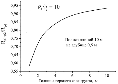
Figure 2
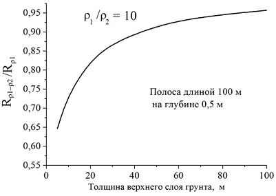
Figure 3
Полоса длиной 10 м – tape (в нашем словарике идет tape, но я бы лучше strip поставила) 10 m in length
На глубине 0,5- at the depth of 0,5 m
Толщина верхнего слоя грунта, м- thickness of the upper ground layer, m
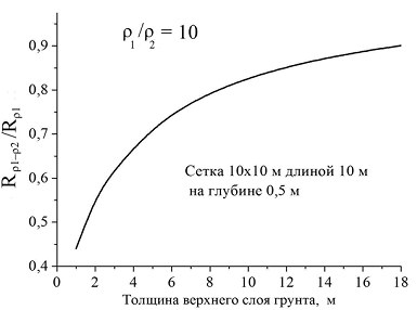
Figure 4
Сетка 10*10 м длиной 10 м – mesh 10x10m 10 m in length
На глубине 0,5- at the depth of 0,5 m
Толщина верхнего слоя грунта, м- thickness of the upper ground layer, m
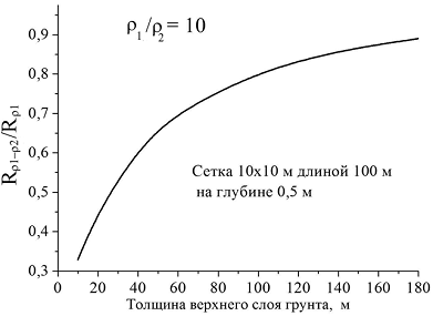
Figure 5
How effective is the artificial treatment of the surface soil layer?
The answer to this question has already been prepared in the previous section. The consequences of treatment of a relatively thin upper soil layer are fundamentally different for grounding devices of different lengths and areas. A professional understands that a thick layer of soil cannot be chemically treated, especially on a large area. It is practically possible to replace rock, to say, clay or humus to a depth of several meters, but it will cost a lot of money. Therefore, it is advisable to analyze the effects of changes in ground conductivity at a very moderate depth (1-3 m). The results of typical calculations are presented in Fig. 6.
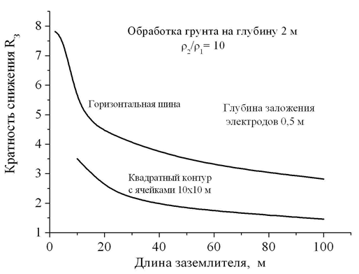
Figure 6
Кратность снижения - reduction ratio
Обработка грунта на глубину 2 м – soil treatment two meters deep
Горизонтальная шина - horizontal bus
Глубина заложения электродов 0,5 м – electrodes burial depth 0,5 m
Квадратный контур с ячейками 10*10 м - square contour with cells 10x10m
Длина заземлителя, м – ground electrode length, m
We considered ground electrode systems in the form of horizontal bus of different lengths and a square shaped mesh of horizontal buses with cells of 10x10 m. It was assumed that the ground electrode is laid at the depth of 0.5 m in the upper 2-m layer of treated soil with a resistivity ρ1. It is assumed that as a result of processing the value ρ1 dropped 10 times (very effective treatment!) as compared to the resistivity ρ2 of the lower untreated layer of unlimited thickness. The simulation showed that the consequences of such a difficult operation affect the grounding resistance the less, the greater are the sizes of the grounding device. Since for a 2-meter bus the reduction ratio R3 close to 8, differed slighty from the value of ρ2/ p1 = 10. For a 10-meter bus, this parameter decreased to 5, and for the 50 m - down to 3. With regard to the square mesh the effect was even weaker; it did not exceed 1.5 at the side length of the square of 100 meters. I must say that this is not the limit size for grounding contours of modern technical facilities. The attempt to achieve a more significant effect is unlikely to be very successful. Even with the increase in the thickness of the treated layer of up to 5 m , the grounding resistance of the contour of 100x100 m is about 5 times higher than could be obtained in a homogeneous soil with the same resistivity ρ1.
The resistivity of the lower undisturbed layer of the ground has a very significant influence on the consequences of soil treatment (or surface replacement). This is demonstrated by the results of a particular calculation in Fig. 7 for the same grounding contour 100x100 m with cells of 10x10 m. The top soil layer with the resistivity of 100 ohm * m, where the contour is placed, at its unlimited thickness, would provide the grounding resistance of 0.46 ohms, which would make it suitable for facilities with voltage over 1000 V with a solidly-earthed neutral. Real values of grounding resistance at the thickness of the upper layer of 5 m 3 are shown in Fig. 7, depending on the resistivity of the main untreated soil. They differ from the ideal within an order of magnitude or more.
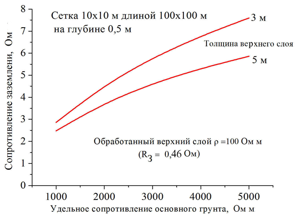
Figure 7
Сопротивление заземления, Ом
Сетка 10*10 м длиной 100*100 м – mesh 10x10m 100x100 m in length
На глубине 0,5 - at the depth of 0,5 m ИЛИ 0,5 m deep
Толщина верхнего слоя – upper layer thickness
Обработанный верхний слой – treated upper layer
Удельное сопротивление основного грунта, Ом м – Main soil resistivity, Ohm m
The effects of climatological changes in soil characteristics
Two parameters influence to the greatest extent - soil moisture and its temperature. The latter one is especially important in winter, when the ground freezes to a considerable depth (in central Russia to 1-1.5 m.). The practice is mainly concerned about the climatological increase of the upper soil layer resistivity, which increase the grounding resistance. From the said above it is clear that the extent of its growth depends on the geometric dimensions of the ground electrode ceteris paribus.
As an example, Fig. 8 shows the time course of the grounding resistnce of a horizontal bus 3 m long earth, the measurements were performed by "Amnis" LLC in Moscow region during the recent year. The scale of the measured values is approximately twofold, from 50 to 100 ohms. I believe that an attentive reader will refuse to read further. It is hard to escape a conclusion from everything said above. Surface change of soil, significantly affecting the ground electrode resistance of relatively small length, will develop in a less degree0 at the increase of overall size of the ground electrode system. It is really so. Suppose, for example, during a drought the ground surface layer increased its resistivity tenfold at the depth of 1.5 m. How will it change the grounding resistance R3 of a flat square contour with cells 10x10 m, see computer simulation results in Fig. 9. It is seen that with the increase of the total contour length from 10 m to 250 the growth ratio R3 drops from 5 to 1.5. The size of the grounding contour very poorly affects the result of the estimations.
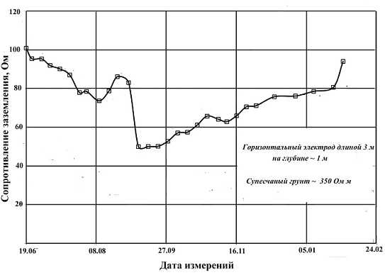
Figure 8
Сопротивление заземления, Ом – Grounding resistance, Ohm
Горизонтальный электрод длиной 3 М - horizontal electrode 3 m long
На глубине – 1 м – 1 m deep
Супесчаный грунт – 350 Ом м –sandy-loam soil – 350 Ohm m
Дата измерений – Date of measurements
E. M. Bazelyan, DEA, professor
Energy Institute named after G.M. Krzyzanowski, Moscow
Read more "Measuring grounding resistance".
Useful materials:
- Series of articles about lightning protection for beginners
- Series of webinars about grounding and lightning protection with Professor E. M. Bazelyan
- Elements of external lightning protection
- Consultations on the selection, design and installation of grounding and lightning protection systems
Related Articles:
