From the series of articles "Grounding in lightning protection - answers to frequently asked questions in the design".
This is supposed to be done in the process of completing the installation and before each stormy season. The principle of operation of any gauge comes down to the method of ammeter and voltmeter. A built-in generator of the device loads the controlled ground electrode system with the current of known value I, and the voltmeter measures the voltage on the ground electrode U3 with respect to the point at infinity. According to Ohm's law, the quotient of these values gives the grounding resistance. R3 = U3/I. The problem of organization of measurrements is only connected to the circuit wiring. To apply the current, an auxiliary current electrode should be placed into the soil, and to measure the voltage, it is necessary to find the "infinity" point of zero potential, in order to put another auxiliary electrode into it for voltmeter connection. All this requires considerable space. Otherwise, mutual influence between the electrodes and their distortion of current spreading regime cannot be excluded. That's how it is recommended to place the measuring circuit elements in the existing guidelines (Fig. 10).
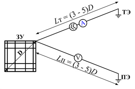
Figure 10
Here again, everything is defined by the maximum overall dimension of the grounding device. The bigger it is, the slower is the potential decrease in the soil at the current spreading. It will drop to zero at infinity, and it is impossible to reach it with sensing wires. We have to agree to some error, for example, in the range of 10% (for lightning protection matters the accuracy is quite decent). CalculatIon correspondences in Fig. 11 and 12 show how the potential reduces at the surface in the vicinity of an extended horizontal bus of 10 mm in radius and in the vicinity of the grounding contour with a mesh of 10x10 m formed of the same buses. In the first case, to achieve the desired potential reduction it is necessary to remove from the ground electrode to the bus length at least, in the second case - to two diagonals of the contour. These distances may not be small, because the grounding contour with a diagonal of 200 m or more is not uncommon. However, the guidelines recommend even greater distances. They are necessary to eliminate the disturbing influence of the auxiliary electrode through which the current of the grounding load is closed.
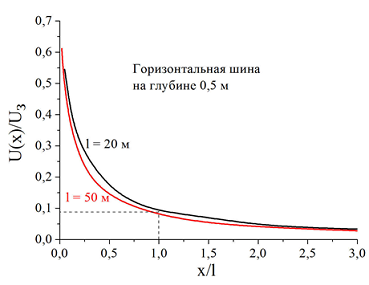
Figure 11
Горизонтальная шина на глубине 0,5 м horizontal bus at the depth of 0,5 (horizontal bus 0,5 m deep)
Контур заземления- grounding contour
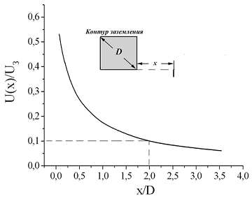
Figure 12
Correction of methodical measurement errors
The article has mentioned a complete analogy of fields of electric charges and of DC. If to position electric point charges of opposite sign at some distance, there will always be a point of zero potential on a straight line between them, because bipolar charges create different signs of potentials. Electrodes with a current in the ground are similar to these charges. The current flows into the ground from one electrode (even if it is conditionally positive), and the electrode collects current from the ground (electrode with negative current). Maybe we should not go to infinity, and the search for a zero potential point on the straight line between the electrodes? A compact scheme with the arrangement of all electrodes on a straight line was born so (Fig. 13)
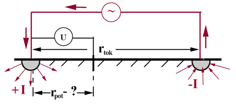
Figure 13
If the electrodes are actually pointlike (or, as shown on the figure, hemispherical) the zero potential point has nothing to look for - because it will be located exactly in the middle between the electrodes due to symmetry. But it turns out that for a correct measuring of the resistance, it is necessary to plunge the potential electrode into the ground not in it but in some other place. Now to prove it we cannot avoid calculations, although they are extremely simple.
The analogy with the equations of electrostatics puts a formal identity between the electric charge q and current I, and soil conductivity γ = 1 / ρt becomes the analogue of the permittivities ε. With this analogy, the voltage at the secluded hemisphere of radius r0 relative to the point of zero potential is equal to
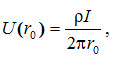
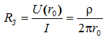
which leads to a well-known expression for grounding resistance of a hemisphere in homogeneous soil
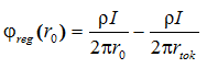
During measurements in the near distance r from each othertok there are two electrodes with currents of different directions I and -I. Now, we should take into account the superimposing principle, according to which in a linear medium the potential of any point is defined as the sum of the capacities of all existing sources and that is why the measured voltage is less
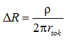
The second term in this formula defines the error that undertakes the value of the measured resistance with respect to the true value by an amount
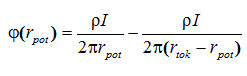
To compensate this error, the voltage measurement on the ground electrode system must be carried out not with respect to the point of zero potential, but with respect to some point at the distance rpot, where the potential φ (rpot) Is negative, so that the measured voltage Ureg = φreg(r0) - Φ (rpot) wil increase.
Naturally, the potential at point rpot is defined by two currents:
There will be no error in measurement in the case of the equation's satisfaction.
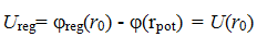
I suggest the reader to substitute all the values found into the recent formula, to make a reduction of similar members, and having receive an expression
solve it relatively the desired distance rpot, where it is necessary to place the potential electrode. Those who did not forget school algebra will manage.
Recommendations in national regulations
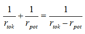
A seductive recommendation, without hesitation, to establish a potential electrode at the distance of 0,62rtok from the measure ground electrode system of any design did not take root in Russia. National experts didn't see any considerable reasons for the spreading of private output to the ground electrode system of any design. But the method of placement of all electrodes on the same line is actually legalized (AD 153-34.0-20-525-00). The distance from the ground electrode to the auxiliary current electrode is recommended to be selected from the condition rtok ≥ 3D, where D - the maximum overall size of the grounding device. A potential electrode sequentially, with increments of Δd = 0,1rtok is placed on a straight line connecting the grounding electrode with the current electrode and measure the voltage between the grounding electrode and the potential electrode or ground resistance directly (if the measuring tool is calibrated in ohms). Next, the dependence of the measured values on the potential electrode position is built (Fig. 14). If the measurement in points rpot = 0,4rtok and rpot = 0.6rtokdiffer within 10%, it is assumed that the true value of ground resistance corresponds to the location of the potential electrode at the point rpot = 0.5rtok.
Figure 14
Измеренное значение – Measured value
The technique becomes more complicated when the curve in Fig. 14 does not have an explicit flat region. Then the recommended measurements and plotting should be repeated for rtok = 2D. Further, it is assumed that the intersection point of the constructed curves (in relative coordinates rpot/rtok on the x-axis) determines the "right" place of placing of the potential electrode.
The recommended construction procedure does not cause any problems for single horizontal bars or vertical rod electrodes. The measurements give a picture very similar to Fig. 14, the condition with 10% discrepancy between the results in points rpot = 0,4rtok and rpot = 0.6rtok is usually performed and that is why, it is possible to clearly define the point of zero potential. Besides single horizontal electrodes, and moreover vertical, rarely have a very long length, which allows to satisfy the condition rtok ≥ 3D. The situation for large area grounding contours is much more complicated. Their diagonal can easily exceed 200 - 300 m. It is a big luck to find free space of almost a kilometer in the area of urban or industrial development. In addition, the grounding contour of even not too large size no longer fits the requirements of the guidelines.
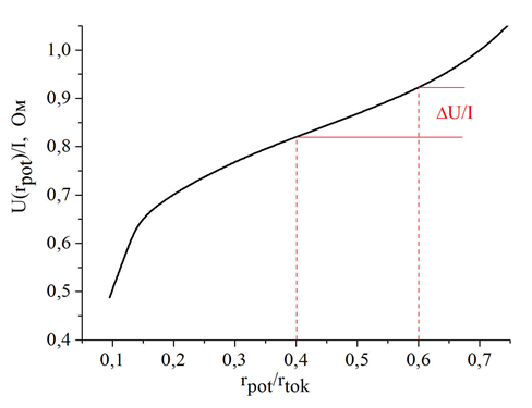
Figure 15
In fig. 15 computer simulation reproduces the results for the grounding contour, the role of which is played by a strip reinforced concrete foundation of the building with the area of 50 x 50 m2. The foundation is sunk 3 meters deep into the ground. It is easy to make sure that the values of the voltage with respect to points rpot = 0,4rtok and rpot = 0.6rtok differ by more than the prescribed 10%. In addition, the built curve has no explicit horizontal section. If you follow the "Methodical guidelines", another series of measurements at rtok = 2D would be required here.
It is useful to remember that any Guidelines are of advisory character. It makes sense to study these guidelines. And it is more convenient to start from the approach to the definition of zero potential point. On the constructed curve it coincides with the inflection point and is determined by the extremum of the first derivative. Don't be afraid of a bit forgotten words. We won't have to do anything complicated. The voltage values between the grounding electrode and the potential electrode as it moves in increments of Δr = 0,1rpot are already measured. It is enough to subtract the previous measurement U k-1 from each successive measured values eg U k, and put the resulting value ∆U = U k – U k-1 on the diagram for the value on the abscissa, corresponding to the middle of the interval on which potential electrodes were placed. The points obtained this way will describe a representative curve with a minimum. Position of the minimum - is the zero potential point (Fig. 16).
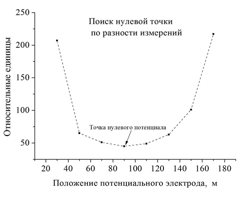
Figure 16
Относительные единицы- relative units
Поиск нулевой точки по разности измерений - search of zero point on different measures
Точка нулевого потенциала - zero potential point
Положение потенциального электрода, м - potential electrode position, m
We can do it even easier. Immediately measure the voltage between a pair of potential electrodes, placed at a distance Δr = 0,1rpot from each other, sequentially moving along the straight line from the variable ground electrode to the auxiliary current electrode. The minimum of these values determines the position of zero potential point. It will be approximately in the middle between the potential electrodes in the "minimum" dimension. It is not necessary to choose the displacement step of potential electrodes equal to Δr = 0,1rpot. It is important for it to be identical.
Now, when everything is clear with the zero potential point, it is useful to understand whether it is necessary to determine the ground resistance. Please, don't be surprised to the arised question. The voltage setting the value of ground resistance after dividing by the current value is measured relative to the point of zero potential. From all the said above it is clear that, due to its electric field, the presence of the current electrode reduces the potential of the controlled ground electrode system. As a result, the measured resistance is lower (in certain circumstances, much lower) than its actual value. Remember that the recommendation to place a potential electrode not in the point of zero potential, but at a distance rpot = 0,62rtok from the ground electrode system emerged to compensate the methodological error. The computer model makes it possible to hold a series of numerical experiments to verify this for the ground electrode systems of diverse designs. Their results are in edge of you (fig. 17-20).
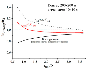
Figure 17
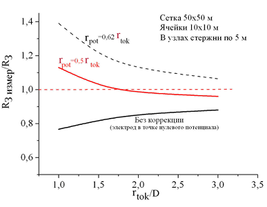
Figure 18
Контур – contour
С ячейками – with cells
Сетка – Mesh
Ячейки – cells
В узлах стержни по 5 м – 5 meter rods in the assembly
Без коррекции (электрод в точке нулевого потенциала) – without correction (electrode in zero potential point)
As expected, the measurements on the zero potential point underestimate the value of ground resistance, although the relative error in the case of a prescribed removal of the current electrode to the distance rtok ≥ 3D is within 10-12%. This is quite acceptable for practice. The measurements at the removal of the potential of the electrode to the distance of 0,62rtok should be considered as overcompensated, although at rtok ≥ 3D, the error is also within 10%.
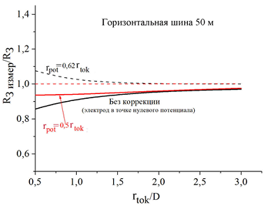
Figure 19
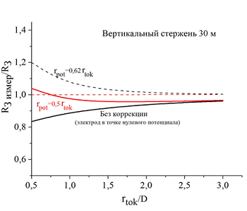
Figure 20
Горизонтальная шина – horizontal bus
Без коррекции (электрод в точке нулевого потенциала) – without correction (electrode in zero potential point)
Вертикальный стержень- vertical rod
The most attractive are the measurements with the placement of the potential electrode exactly halfway between the ground electrode and the current electrode. Under these conditions, the measurement error is not just minimal, but it does not exceed 10%, even in case of reducing the distance rtok up to 1.0D! This simplification of the measuring procedure cannot be overestimated, when they are held in a limited free space.
E. M. Bazelyan, DEA, professor
Energy Institute named after G.M. Krzyzanowski, Moscow
Read more "Individual grounding contour - how real is it?".
Useful materials:
- Series of articles about lightning protection for beginners
- Series of webinars about grounding and lightning protection with Professor E. M. Bazelyan
- Elements of external lightning protection
- Consultations on the selection, design and installation of grounding and lightning protection systems
Related Articles:
