See the complete instructions on grounding and lightning protection for a single-family house (in pictures), on a separate page.
Today almost every country house is equipped with electrical appliances. The safety of their operation is ensured by the connection of the electrical equipment installed in the premises with the grounding device. A correctly implemented protective grounding will eliminate the chance of hitting people with electric shocks and prevent the breakdown of household appliances and complex technical overvoltages, if they are protected by the SPD. The choice of connection scheme depends on various factors. In a single-family house, unlike an apartment one, grounding can be made independently. This instruction will help to understand the issue.
The main elements of the grounding connection scheme of the farmhouse and the rules for their implementation
The scheme of grounding connection in a country house is as follows: electrical appliance - socket - electric switchboard - grounding conductor - grounding contour - ground.
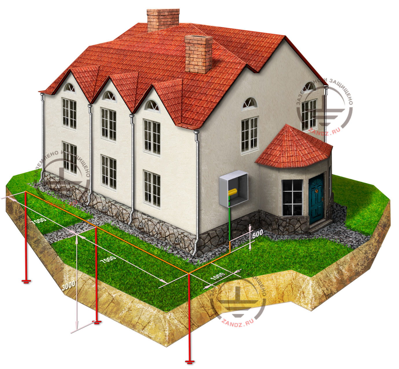
The connection starts with the execution on the private garden space of the grounding device in accordance with the rules defined in Chapter 1.7 EIC of the 7th edition. A ground electrode is a metal structure having a large area of contact with the ground. It is designed to equalize the potential difference and reduce the potential of the grounded equipment, in case of a short circuit to the body or occurrence of excessive voltage in the electrical network. The design and the depth of its installation is determined based on the resistance of the soil on the site (for example, dry sand or wet black soil).
From the grounding device (grounding) made on the site, we lay the grounding conductor, which is connected to the main grounding bus, using a bolted connection, clamping or welding. We choose a conductor of at least 6 mm2 for copper and 50 mm2 for steel, and it must meet the requirements for the protective conductors specified in Table 54.2 GOST R 50571.5.54-2013, and for the TT system, a cross section should be at least 25 mm2 for copper. If the conductor is bare and laid in the ground, then its cross-section must correspond to that given in Table 54.1 of the GOST R GOST R 50571.5.54-2013.
In the electric switchboard, the grounding conductor is connected to the protective conductors through the ground bus to the outlets that have a ground contact and the rest of the electrical receivers in the house. As a result, each electrical appliance is connected to the grounding system.
Dependence of the grounding connection scheme on the grounding contour
If the post of the power transmission line is re-grounded, then the grounding connection in a country house is performed using TN-C- or TT systems. When the condition of the networks is not a concern, you should use a repeated grounding of the line as a grounding device at home and connect the house in accordance with the TN-C-S grounding system. If the overhead line is old, or the quality of repeated grounding is subject to doubt, it is better to select a TT system and equip an individual grounding device in the private garden space.
First of all, one should use natural ground electrodes for a grounding device - third-party conductive parts that have direct contact with the ground (water pipes, well pipes, metal and reinforced concrete structures of a country house, etc.). (See clauses 1.7.54, 1.7.109 EIC, 7th edition).
In the absence of such, we perform an artificial grounding device, using vertical or horizontal electrodes, which we dig into the ground. The choice of the grounding device configuration is mainly dependent on the required resistance and the features of the private garden area.
In the absence of such, we perform an artificial grounding device, using vertical or horizontal electrodes, which we dig into the ground. The choice of the grounding device configuration is mainly dependent on the required resistance and the features of the private garden area.
It is most effective in use, if the soil on your plot is represented by loam, peat, water saturated sand, watered clay. The standard length of the rods is from 1.5 to 3 m. When choosing the length of vertical electrodes, we start with the water saturation of the country rocks on the garden plot. Buried ground vertical ground electrodes are united by a horizontal electrode, for example tape, and to minimize the shielding are located at the distance commensurate with the length of the rods themselves.
The construction of the grounding device is recommended to be located at the distance of one meter from the foundation of the building (see 1.7.94 of the EIC of the 7th edition).
Dependence of the connection scheme on the type of the grounding system
Grounding of housing facilities is performed on the following systems: TN (subsystems TN-C, TN-S, TN-C-S) or TT. The first letter in the title indicates grounding of the power source, the second - grounding of the open parts of the electrical equipment.
The subsequent letters after N indicate the alignment in one conductor or separation of functions of the zero working and zero protective conductors. S - zero working (N) and zero protective (PE) conductors are separated. C - functions of the zero protective and zero working conductors are combined in one conductor (PEN conductor).
Electrical safety is ensured fully, when a decrease in the resistance of the ground electrode does not entail an increase in the closing current to the ground. Let's consider how the grounding connection scheme depends on the electrical network performed at the facility.
TN-S grounding system
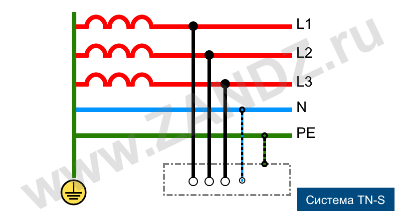
Figure 1. TN-S system
In the facilities equipped with the TN-S system, the neutral working and protective conductors are separated along the entire length, and in the event of a breakdown of the phase insulation, the emergency current is routed through the protective PE conductor. The SPDs and differential automate reacting to the leakage current through the protective zero, disconnect the network with the load.
The advantage of the TN-S grounding subsystem is the reliable protection of electrical equipment and people against emergecny current shocks when using electricity mains. Due to what this system is considered to be the most modern and safe.
To perform grounding in the TN-S system, it is necessary to install a separate ground wire from the transformer substation to its structure, which will lead to a significant rise in the cost of the project. For this reason, the TN-S grounding subsystem is practically not used for grounding of the private sector objects.
TN-C grounding system. Necessity of transition to TN-C-S
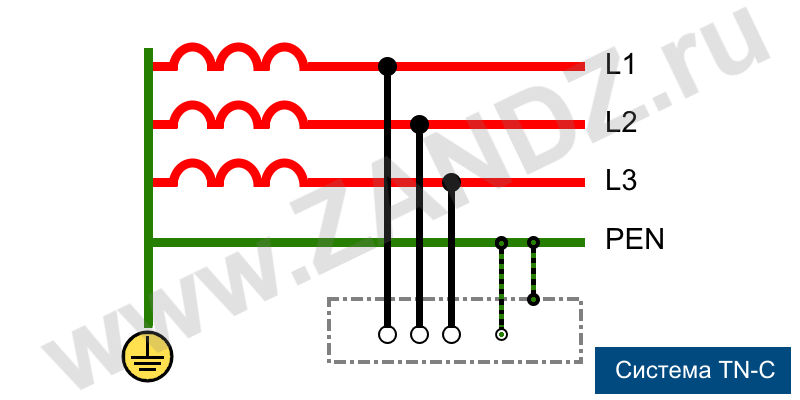
Figure 2. TN-S system
Grounding on the TN-C system is most common for old buildings of the housing stock. Its advantage is economy and easy implementation. A significant disadvantage is the absence of a separate PE conductor, which excludes the presence of grounding in the outlets of the country houses and the possibility of equalizing the potentials in the bathroom.
Electric current is supplied to the country houses by air lines. Two conductors are connected to the structure: phase L and combined PEN. It is possible to connect the grounding only if there is a three-wire wiring in a house, which requires the change of the system from TN-C to TN-CS, by separating the zero working and zero protective conductor in the electric switchboard (see 1.7.132 of the 7th edition of the EIC).
TN-C-S system grounding connection
The TN-C-S grounding subsystem is characterized by the combination of the zero working and zero protective conductors on the garden plot from the power lines to the building entry. Grounding on this system is quite simple in technical performance, due to which it is recommended for wide application. Its disadvantage is the need for constant modernization, in order to avoid the breakage of the PEN conductor, as a result of which electrical appliances can be under dangerous potential.
Let's consider the scheme of grounding connection in a country house on the TN-C-S system on the example of transition to it from the TN-C system.
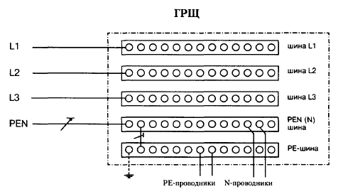
Figure 3. Scheme of the main switchboard
Шина - bus
PE- проводники – PE conductors
N проводники – N conductors
As already noted, to obtain a three-wire wiring, it is necessary to make the correct separation of the PEN conductor in the distribution panel of the house. We begin with the fact that we place a bus into the electric board with a strong metallic connection with it, and we connect the unified PEN conductor coming from the power transmission line to this bus. The PEN bus is connected by a jumper with the next installed PE bus. Now the PEN bus acts as the bus of the zero working conductor N.
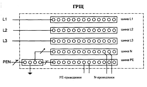
Figure 4. Ground connection scheme (transition from TN-C to TN-C-S)
ГРЩ – MGB
PE- проводники – PE conductors
N проводники – N conductors
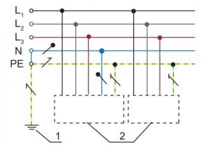
Figure 5. TN-C-S grounding scheme
After completing these connections, we connect the switchboard to the ground electrode: from the grounding device we make a wire to the PE bus. Thus, as a result of a simple upgrade, we have equipped the house with three separate wires (phase, zero protective and zero working).
The rules for the installation of electrical installations require repeated grounding for PE and PEN conductors at the input to electrical installations, using, first of all, natural ground conductors, the resistance of which at 380/220 V should not be more than 30 Ohm (see 1.7.103 EIC of the 7th edition).
TT system grounding connection
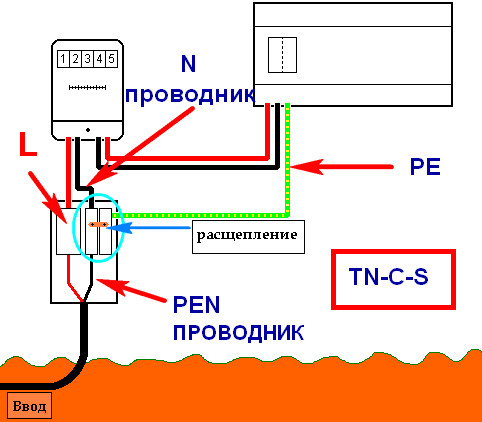
Figure 6. TT system
PEN- проводник – PEN conductor
N проводник – N conductor
Расщепление – spallation
Ввод - input
Another variant of the scheme is to connect grounding of a country house on a TT system with a dead grounded neutral current source. Open conductive elements of the electrical equipment of such a system are connected to a grounding device that does not have an electrical connection with the neutral of the power supply source.
The following condition must be observed: the value of the product of the trip-out current of the conventional operating current of a protective device (Ia) and the total resistance of the grounding conductor and the ground electrode (Ra) must not exceed 50 V (see clause 1.7.59 of the EIC). Ra Ia ≤ 50 V.
To comply with this condition, "Instruction for the installation of protective grounding and equipotential bonding in electrical installations" and 1.03-08 recommends the use of a grounding device with a resistance of 30 Ohm. This system is quite in demand today and is used for private, mostly mobile buildings, if it is impossible to provide a sufficient level of electrical safety by the TN system.
Grounding on the TT system does not require separation of the combined PEN conductor. Each of the individual wires suitable for the house is connected to the bus isolated from the electric switchboard. And the PEN conductor, in this case, is considered to be a zero wire (zero).
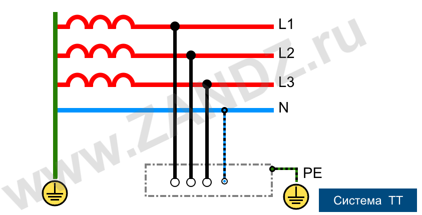
Figure 7. Scheme of grounding connection according to TT system
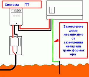
Figure 8. Scheme of grounding connection and RCD on the TT system
Заземление дома независимо от заземления нейтрали трансформатора – Grounding of a house regardless of the grounding of the transformer neutral
As follows from the scheme, the TN-S and TT systems are very similar to each other. The difference is in the total absence of the electrical connection between the grounding device and the PEN conductor in the TT system, which, in the event of the latter being fired from the power supply side, ensures that there is no excess voltage on the body of electrical appliances. This is the obvious advantage of the TT system, which provides a higher level of safety and reliability in operation. The disadvantage of its use can only be the high cost, because in order to protect users from an indirect touch, it is mandatory to install additional devices for protective power disconnection (RCD and voltage relay), which in turn requires the process of approbation and certification by the expert of energy surveillance.
Conclusion
The grounding scheme in a general form is a combination of its elements: electrical equipment, main distribution board, PE grounding conductor, ground electrode.
To install a grounding device in a country house, you need to understand the features of its connection, depending on the following factors:
- method of supplying the electrical network (by air lines or cable from a transformer substation)
- type of soil in the house area where the grounding contour is being executed.
- presence of a lightning protection system, additional power supplies or specific equipment.
When making grounding connection yourself, you must follow the provisions of section 1.7 of the Electrical Installation Code. If it is not possible to use natural ground electrodes, we carry out a grounding device with the use of artificial ground electrodes. Grounding of a private house can be performed by two systems: TN-C-S or TT. The most widely used was the upgraded TN-C-TN-C-S system, due to the simplicity of its technical execution. To ensure the electrical safety of a country house through the TN-C-S system, separation of the PEN conductor to zero working and zero protective conductors is required.
After making the grounding contour, it is necessary to check the quality of its installation, and to make resistance measurements for the compliance with the norms of the EIC with the help of special instruments, which may require the involvement of specialists.
See the complete instructions on grounding and lightning protection for a single-family house (in pictures), on a separate page.
Do you need advice on the organization of grounding and lightning protection for your facility? Contact ZANDZ.com Technical Centre !
See also:
- Surge protection of a single-family house
- Single-family house lightning protection
- Calculation example of lightning protection of a private house and a bath house
- Video recording of the webinar with Professor E.M. Bazelyan "Protecting the private sector"
- Grounding for lightning protection (requirements, equipment)
Related Articles:
 Step Voltage: Dangerous Obscurity and Reliable Protection
 Nature of Electrochemical Corrosion
 Public Safety in Land Transport in case of Direct Lightning Strike