Grounding parameters depend on many factors, and not all of them can be taken into account in the calculations. Therefore, after installing the grounding, it is recommended to repeatedly measure its resistance at different seasons of the year. Grounding elements can oxidize and corrode, so it is also necessary to periodically measure the grounding resistance even after you have verified that everything was done correctly. The current standards in Russia require measuring the grounding resistance of electrical installations at least once every 12 years. For the supports of power lines with circuit breakers, protective gaps, arresters, re-grounding of the neutral wire, the measurement of grounding resistance is carried out annually. Also, annually grounding parameters at 2% metal and reinforced concrete supports of power lines passing in populated areas are selectively measured.
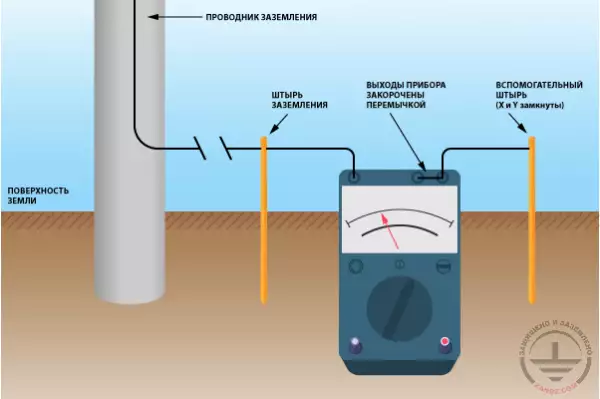
Classical methods for measuring resistance involve the installation of additional grounding pins (electrodes) at a distance of about 20 m from the test ground. This can be a problem if during the measurement process the pins have to be installed at the territory owned by somebody. In addition, problems may arise with the installation of additional pins in winter in frozen ground. But it is precisely the freezing situation that is the most problematic in terms of functioning of grounding. For example, in permafrost regions, rules of technical operation of electrical consumers prescribe measuring the grounding resistance of power lines only during the period of the greatest freezing of the soil. Another disadvantage of traditional methods of measuring resistance is the need to disconnect parallel-connected grounding.
These circumstances make it relevant to use the so-called non-electrode methods for measuring ground resistance not requiring the installation of additional pins into the ground. This has been made possible thanks to modern current clamps.
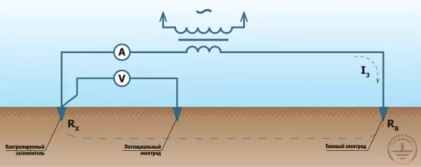
The principle of non-electrode method for measuring grounding resistance is as follows. An alternating current of a given voltage with a frequency different from the mains frequency is supplied to ground from the measuring generator. The current strength in grounding is measured by special current clamps with a filter that makes them sensitive only to the frequency at which the measuring generator operates. According to the obtained measurement data of the current flowing into the ground electrode, based on the known value of the voltage applied to the ground, specialized clamps automatically calculate the resistance.
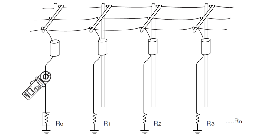
A non-electrode circuit for measuring grounding resistance using current switches
Ground voltage is supplied using other current switches. They are used as a generator and transformer, supplying electricity to ground. The most modern models combine emitting and measuring transformers in a single design that allows the use of only one clamps.
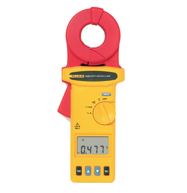
Example of clamps for measuring grounding resistance
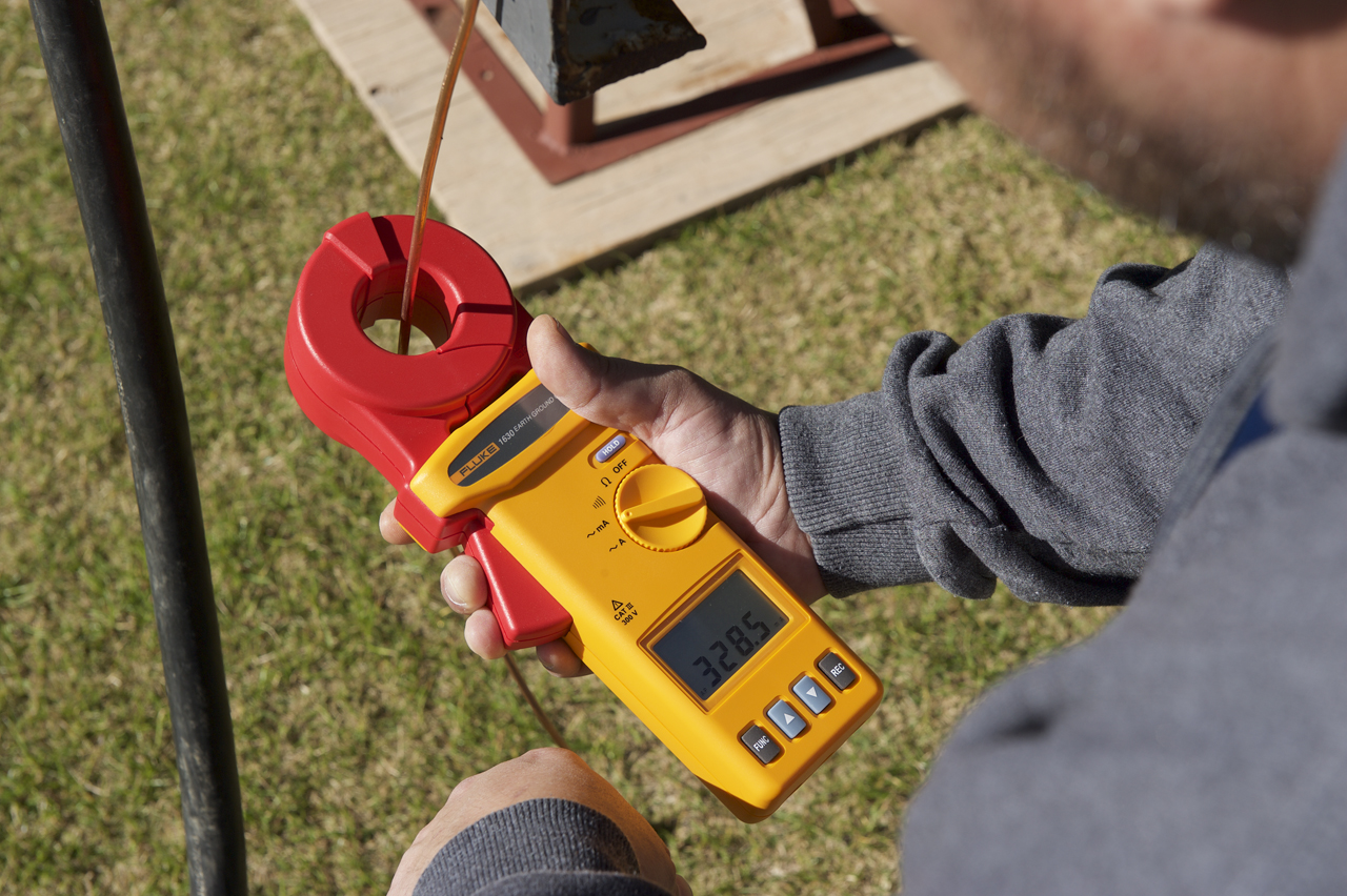
The advantages of an non-electrode ground resistance measuring method are especially evident when lightweight and compact devices are used. For example, Fluke 1630 dimensions of which are only 276 x 100 x 47 mm and weight – 750 g. The device is powered by independent source (alkaline battery), the operating time without replacing the battery is 8 hours. Only one clamp is used in the device, it is enough to clasp a wire or bus leading to grounding and after 0.5 s the resistance value will appear on the display.
Fluke 1630 Ground Resistance Meter
The device is capable of measuring grounding resistance in the range from 0.025 to 1500 Ohms. This range is divided into 7 subranges that are automatically selected. Such a wide range allows the use of the device not only for measuring grounding resistance, but also leakage resistance.
By the way, Fluke-1630 can also be used as ordinary current clamp, measuring current up to 4 A.
Interpretation of measurement results
The accuracy of measuring resistance not exceeding 100 Ohms with the Fluke 1630 is not more than +/- 1.5%. But here it is important to understand what kind of resistance we are measuring.
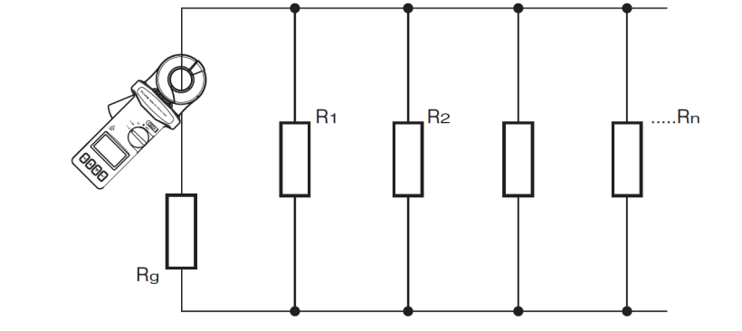
Equivalent-circuit diagram
Consider an equivalent-circuit diagram. It can be seen that the resistance of the electric circuit Rs that includes other groundings and the earth itself, is measured.
Measuring clamps give the value calculated by the formula:
Rs = E/I,
where E - conductor induced voltage, and I - measured current.
Wherein,
Rs = Rg + Rz + 1/(1/R1 + 1/R2 + … 1/Rn),
where Rg is the resistance of the test ground, Rz is the resistance of the soil, n is the number of ground connections connected in parallel to the test.
The sum of Rz and the total resistance of the grounding connected in parallel is much smaller than the maximum permissible value of the grounding resistance (4 - 8 Ohms). Therefore, it is accepted that
Rg ≈ Rs,
and in reality Rg
For measurements, a frequency of about 3 kHz is used. It can also become a source of error, since the inductance of the wires is already beginning to affect this frequency. But, again, the presence of inductance in the wires introduces an error in the direction of increasing resistance.
We can conclude that the method of non-electrode measurement of grounding resistance gives an estimate of the parameter from the top. If you get a certain result, you can be sure that in reality the ground resistance will be slightly lower. This is very important from a safety point of view, since the error of the method cannot fundamentally lead to an underestimated resistance rating when a faulty ground is assessed as good.
Related Articles:
 Measuring the Earthing Resistance Using Conventional Three- and Four-Wire Methods
 Why Cannot Vertical Earthing Devices Be Installed Close to Each Other?
 Electrolytic Grounding in Permafrost Soils: Should Vertical of Horizontal Electrodes Be Used?