When we are talking about the public safety, it is more preferred to use the test methods that have been proved for many years. With regards to the earthing, this method may include the measurement of resistance using a combination of an ampere-meter and a voltmeter (recommended by GOST R 50571.16-2007). Sometimes, this method is called a "three-wire" (or a "three-clamp") method. Its more precise modification exists and is called a "four-wire" (or a "four-clamp") method. Typically, both methods can be implemented in the same measuring device.
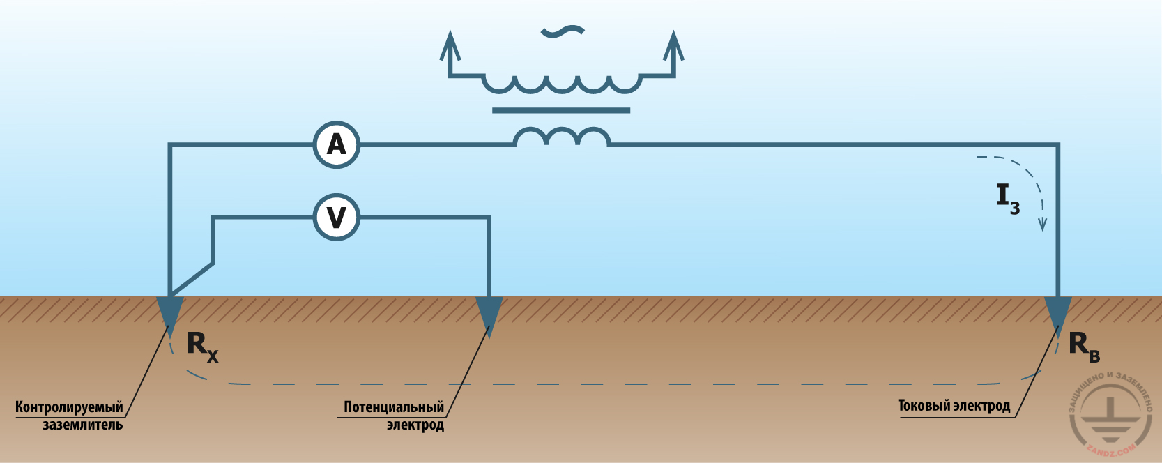
Measuring the earthing resistance using an ampere-meter and voltmeter method
Контролируемый заземлитель - Controlled earthing device
Потенциальный электрод - Potential electrode
Токовый электрод - Current electrode
When measurements are done using this method, the earthing is disconnected from the electrical installation. A potential rod is buried at the distance of at least 20 m from the test earthing. A current rod is buried at the distance of at least 40 m from the test earthing. The rods and the earthing system should be located in a single line. The particular distance recommendations for the earthing system and the rods may differ depending on the earthing type and the model of the used measuring equipment. Such recommendations are usually specified in the measuring instrument manual.
The alternating current is supplied through the transformer to the circuit formed by the test earthing, the current rod, and the ampere-meter. In the modern devices, this is typically not a 50 Hz sinusoid, but a meander with the frequency of about 100 to 200 Hz. Thus, the operability of the earthing system is tested with higher order harmonics, and we can partially reduce the interference effects. Using the voltmeter, a voltage between the earthing system and the potential rod is measured. Then, based on the Ohm's law, the earthing resistance is calculated using the formula:
R = U/I,
where U is the voltage between the earthing system and the potential rod, and I is the current in the circuit formed by the earthing system, the current rod, the transformer, and the ampere-meter.
A common problem of the convential method for measuring the earthing resistance is an effect of earth currents.
In real practice, the ampere-meter and voltmeter method is of two types: the three-wire and four-wire methods that will be described below.
A three-wire method
Let's designate the terminals for voltage measuring as W1 and W2, while the terminals for current measuring are designated as T1 and T2. In the real measuring devices, these terminals may be designated in a different way.
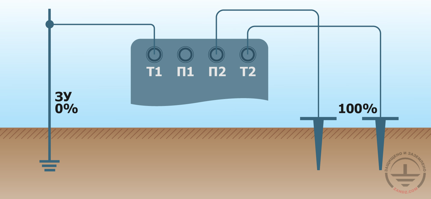
Three-wire measurement
ЗУ - ED
Т1 - T1
П1 - W1
П2 - W2
Т2 - T2
In the three-wire method, terminals W1 and T1 are connected with a jumper and attached to the test earthing with one wire. Terminal W2 is connected to the potential rod with a wire, and terminal T2 is connected to the current rod.
The benefit of the three-wire method includes lower number of wires. The disadvantage includes a strong effect of the resistance of the wire going to the earthing system on the measurement results. Therefore, the three-wire method is usually used to measure the earthing resistance with the value being definitely more than 5 Ohm.
A four-wire method
When higher requirements exist to the measurement accuracy, the four-wire method is used. According to the method, separate wires go to the test earthing from terminals W1 and T1, which are directly connected at the terminals only.
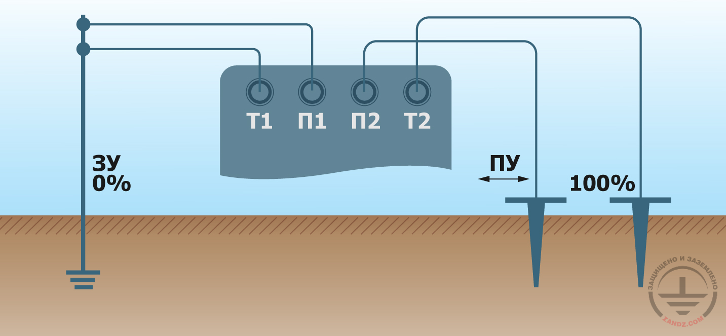
Four-wire measurement
ЗУ - ED
Т1 - T1
П1 - W1
П2 - W2
Т2 - T2
The current flows through the wire that goes to T1. The voltage difference at the wire ends appeared in this case brings in an error to measurements, which is typical of the three-wire method. But according to the four-wire method, the voltage measurement point (at the terminals) is connected to the measuring device with a separate wire. Along this wire, a negligible current flows (not more than several milliamperes), such that its resistance does not almost bring in errors to measurements.
Improving the measurement accuracy
The conventional method for measuring the earthing resistance is sensitive to the soil properties non-uniformity in different locations. Therefore, in order to improve the measurement accuracy, it is recommended to alternate the location of the potential rod several times with a step of about 10% of its rated distance to the earthing system. The measured values scattering should not be more than 5%. If it is more, the distance between the test earthing and the rods is increased 1.5 times, or the line direction along which the rods are installed is changed.
Choosing a measuring device for the earthing resistance
Until now, the literature describing the conventional resistance measurement method have recommended the Soviet instruments. But they do not fit the current conditions because since then, much more electrical equipment has been used in our houses. New devices have appeared (e.g. base stations of the cell communication networks), which declare special requirements to earthing. Hence, it makes sense to use the products offered by the leading world brands. But it is not so easy here since the prices are often high, and there may be differences between the Russian and foreign standards.
The optimal option is the measurement equipment manufacture in China on the basis of the most advanced technologies, however according to the specifications and under the local brand of the Russian company. For example, ZG-4300 (the abbreviation means "Zhelezny Garry", i.e. "Iron Harry"). This device allows measuring the earthing resistance in the range 0.05 Ohm to 20.9 kOhm. Measurements according to the double-, three-, or four-wire methods are available. The voltage at the terminals does not exceed 10 V, which allows conducting measurements with a high electrical safety level. The device does not only conform to the Russian standards. It is included into the State Registry of Measuring Devices. And the price is 3 times lower than that of equivalents of the known foreign brands.
Other measuring methods
The double-wire method for measuring the earthing resistance is simpler yet less accurate. It allows to quickly obtain the resistance estimate, which is important, e.g. for repair works. The method is described in a separate article (link).
Further development of the conventional measurement method has resulted in the so-called null method. It allows tuning away from the interference caused by the earth currents using purely analogue methods. The disadvantage of the method is complicated device configuring and higher requirements to the operator's qualifications; therefore, it has not spread widely.
Moreover, there is a family of electrode-free measurement methods that allow to prevent disconnection of the earthing system from the electrical installation. They are based on the clamp meter application. The method based upon the application of two clamps is also among the ones recommended in GOST R 50571.16-2007. The disadvantage of the method is that it can be directly used in the TT systems and TN systems with cell earthing only. For conventional TN systems, we need a short-time installation of a jumper between the neutral wire and the earthing, which is a potential threat to the electrical safety, so that power in the entire building where the earthing system is installed should be disconnected for the measurement period.
Conclusions
In the digital era, the conventional voltmeter and ampere-meter method is basic for measuring earthing resistances. An extensive experience of its application is accumulated. Therefore, it may be considered reliable. The digital technologies allow calculating the resistance promptly and see the result directly on the screen of a measuring device. Moreover, using the modern technologies, we can significantly reduce the interference during measurements. Thus, the measurement accuracy may be brought to 1–2%, which allows the conventional methods to successfully compete with the methods based on the application of a clamp meter with the prominently higher error.
Related Articles:
 Why Cannot Vertical Earthing Devices Be Installed Close to Each Other?
 Electrolytic Grounding in Permafrost Soils: Should Vertical of Horizontal Electrodes Be Used?