The rod structure of modular ground rodes ensures the maximum ease of installation:
-
any configuration of ground loop
-
all parts are joined without welding
I appreciated the ease of installation.
I've understood I could do the installation works myself, as everything was so thougtfully designed.
Nadezhda Bazhutina,
design department,
PROGRESSTECH Group
The vertical grounding electrodes of the necessary depth are assembled from
1.5-meter rods driven into the ground one after the another using a conventional electric jackhammer (with the impact energy of 20-25 J). The rods are connected together with simple threaded couplers (no welding is necessary). A bolt clamp is used to connect the grounding conductor.
Grounding configuration (single electrode or multiple electrodes) is selected depending on the available space, soil type and the type of facility (residential house or industrial building).
Deep installation of one electrode to a depth of 15 to 30 meters it is the most convenient method that allows to obtain a very effective grounding:
-
Its quality (grounding resistance) does not depend on the weather and time of year
-
It can be mounted within the building perimeter (in the basement)
-
The grounding loop footprint is minimal
-
Earthworks volume is minimal
An example of a modular grounding installation
Installation of electrolytic grounding
The design and technology of electrolytic grounding provide maximum convenience and ease of installation in permafrost, stony and sandy soils.
The installation of such ground:
- does not require a large amount of excavation (compared to conventional methods)
- does not require the digging of deep trenches for laying the ground electrode (the depth is just 0.7 meters)
- does not require construction machinery. The entire installation is performed by two workers in 3 hours' time.
-shaped electrode with perforation over the entire length filled with a special mixture of salts is easily laid in a trench, which is 0.7 meters deep and 2.5 meters long. Once installed, the electrolytic grounding electrode requires no maintenance during the entire service life, providing the required grounding resistance during 50 years.
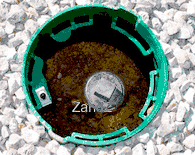
Assembled ZANDZ electrolytic grounding kit
before the final installation step (pit installation and land forming)

Electrolytic grounding installation example
Modular grounding
installation procedure
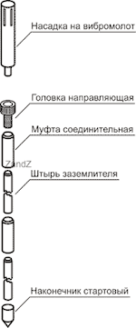
- Preparation of the first rod.
- The inside part of the grounding tip shall be treated with conductive paste and then the tip is put on the rod.
- Apply conducting paste to the inside part of the coupler and screw it all the way to the other end of the rod.
- Screw the jackhammer driving head all the way into the coupler screwed onto the ground rod.
- Note that you need to screw the driving head until full contact with the rod is achieved. This is needed to ensure that the impact energy of the jackhammer is passed through the head to the rod directly, rather than through the coupler. Otherwise, the coupler may break down.
- Drive the rod into the ground by the jackhammer (the impact energy is 20-25 J) to a level comfortable for subsequent operations
- This tool can be rented for a daily charge from some rental companies.
- Unscrew the driving head (without a coupler, as it should remain on the rod).
Apply conductive paste to the coupler that remains screwd onto the rod.
Screw the next rod all the way into the coupler described in p. 4.
Take a new coupler and apply conductive paste on its inside part.
Screw the driving head of the jackhammer all the way into the coupler described in p. 6.
Screw the coupler with the head on it onto the rod connected to the rod, which has been already assembled (see p. 5).
Repeat steps 2 through 9 until the desired depth of the ground electrode is achieved.
Note that when installing the last rod you must leave a portion of the rod above the surface so that you can connect a grounding conductor. - A clamp to connect a grounding conductor is installed on the top of the assembled electrode.
- A grounding conductor (a round-section wire or tape) is connected to the clamp. You can use, for example, a conductor shown on a separate page.
- The place of connection (the clamp) is tightly insulated with waterproofing tape.
- .
Special aspects
of modular grounding installationJoining the ground rods
The rod is oriented blunter end down (into the ground) and a sharper end up during installation.
This is necessary for a more precise junction of rods inside the coupler.
Applying conductive paste
The paste is applied to the threads only inside the coupler (the paste improves the electrical and corrosion properties of the connection).Connecting rods together (via a coupler) Screw the rods together by hand, without the use of special tools. As experience shows, manual effort is enough to tighten the rods, so the use of tools gives no additional effect.
When you drive the rods into a solid or dense soil, the threaded connection is loosening. You can tighten the connection as needed. This is necessary to effectively transmit the impact energy of the jackhammer to the electrode being driven into the soil.
The angle of the jackhammer and the rod with respect to the axis of penetration.


Electrolytic grounding installation procedures
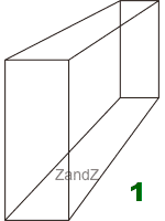
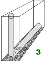
- Dig a trench having a depth of 0.7 meters, a width of 20 cm and a length of 2.5 meters.
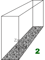
- Spread a 1 cm layer of near-electrode filler (one bag) over the bottom of the trench.
- Clear the electrode from protective/transport film along the electrode's entire length. Place the electrode into the trench with the smaller bended part of the tube facing upwards.
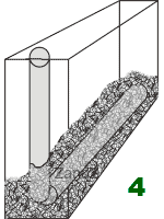
- Fill the horizontal part of the electrode tube with the remaining near-electrode filler (two bags).
- Install an inspection pit on the vertical part of the electrode tube.
- Connect the grounding conductor to the offset of the electrolytic electrode (0.5-meter copper wire). This operation is performed using
- electrolytic grounding clamp included in the kit.
- Insulate the clamp with waterproof tape included in the kit.
- Backfill the trench. The pit cover must be laid flush with the soil.
- Pour 5 to 7 liters of water into the electrode. This is necessary to accelerate the leaching of salts from the electrode.
-
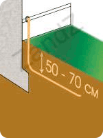
Depth of conductor laying
The surface layer of the soil is exposed to seasonal and weather impacts. Excessive moisture, freezing or thawing of the soil in this layer adversely affect both the ground and the grounding/ connecting conductors laid in the soil.
Moreover, the probability of mechanical damage of wires in the surface layer during household works creates inconveniences and increases the probability of a dangerous situation due to the grounding failure.In most parts of the Russian Federation and CIS countries, the depth of the surface soil layer exposed to the above said types of impact is 0.5 - 0.7 meters.
Therefore, grounding and connection wires should be laid in the ground at this depth (i.e. 0.5 - 0.7 meters) in a prepared trench.Ground electrodes are driven to the same depth.
On-site grounding installation procedures
- Dig a trench having a depth of 0.5 - 0.7 meters at the place where connection wire are to be laid.
- Install ground electrodes in the trench. Please refer to the list of operations included in the "Installation procedures..." for ground electrodes installation instructions.
- Lay the connecting conductor into the trench
- Connect the ground electrodes to the conductor using clamps included in the ZANDZ kits
- Connect the resulting ground to an electric board
- Backfill the trench
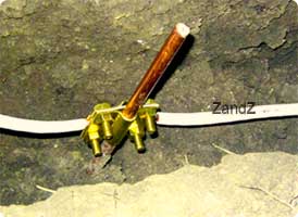
Connecting the ground electrodes
The connection of ground electrodes with each other and the ground with the facility to be protected is done by a steel or copper conductor (wire or tape).
The minimum cross-section of grounding conductor depends on the tasks performed by the grounding system
The connection of ground electrodes with each other and the ground with the facility to be protected is done by a steel or copper conductor (wire or tape).
The minimum cross-section of grounding conductor depends on the tasks performed by the grounding system.
For copper conductors, 50 mm² cross-section is often chosen; 150 mm² cross-section for steel conductors is often used. A conventional 5 * 30 m m steel tape is widespread.
The conductor is laid at a depth of 0.5 - 0.7 meters into a prepared trench (where electrodes are also installed).
A special clamp is included in the ZANDZ kit is used to connect the ground electrode to the conductor.
Related Articles:
 Grounding in the cellar of the single-family house - is it possible?
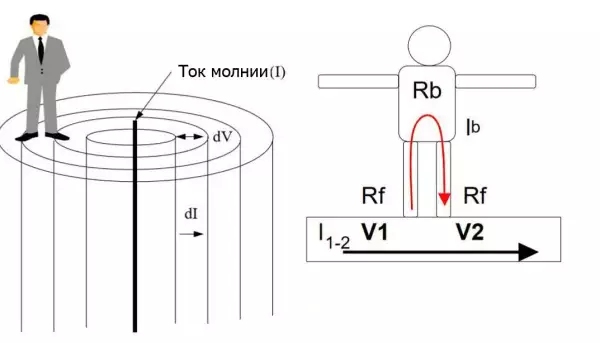 Step Voltage: Dangerous Obscurity and Reliable Protection
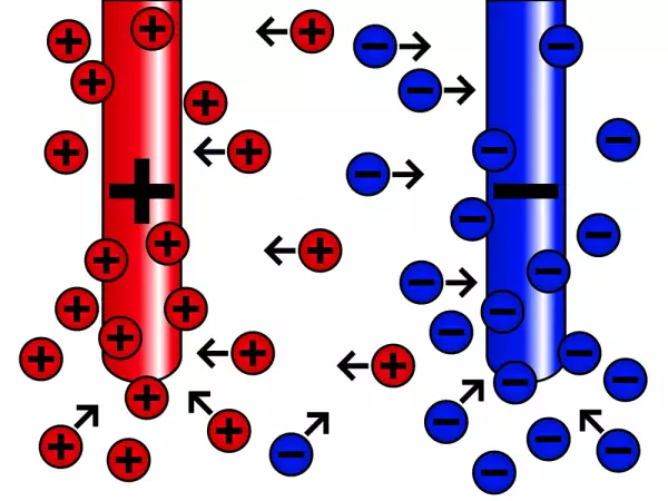 Nature of Electrochemical Corrosion
 Public Safety in Land Transport in case of Direct Lightning Strike