Measuring the grounding arrangement resistance is an important part of checking and evaluating the efficiency of the grounding system. The process plays a key role in ensuring the safety of electrical installations and protecting people from electric shock. The article discusses the specifics of measuring the resistance of a grounding arrangement, typical errors the specialists may encounter, and basic safety principles when making such measurements.
Why do we need to measure the grounding arrangement resistance?
A grounding arrangement is a system of conductors that is designed to provide a safe current path during an earth fault. It prevents dangerous potentials on metal structures, equipment, pipes, and other elements that a person may come into contact with. The grounding resistance determines the efficiency of the arrangement, since a resistance that is too high can lead to dangerous voltages, while a resistance that is too low can lead to the system's unreliability.
The resistance standards for a grounding arrangement may depend on the type of the facility and its purpose, but in most cases, they should not exceed 4 Ohm for most industrial and residential facilities. This is important to minimize the risk of electric shock.
Process of grounding arrangement resistance measurement
To accurately measure the grounding arrangement resistance, use special ohmmeters designed to measure low-range resistances. Remember that measurements must be carried out in accordance with the established standards and methods.
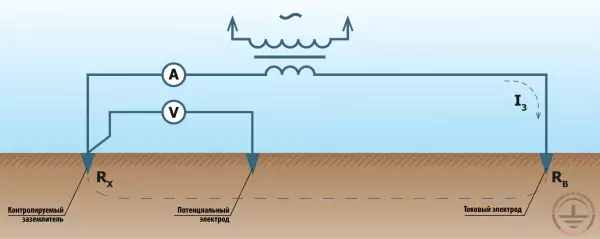
One of the most common methods of measuring the grounding arrangement resistance is a three-electrode (or four-wire) measurement method, see the images below. This method includes the following steps:
- Installation of measuring electrodes: One of the electrodes is placed into the ground next to the grounding arrangement (used as the main electrode). The second electrode is placed at a certain point at a distance from the main electrode (at a distance of several meters to several dozens meters depending on the soil type and the required measurement accuracy).
- Voltage and current measurements: A measuring device is used to determine the current and voltage passing through the grounding arrangement. Based on these data, the resistance is calculated.
- Resistance determination: During the measurement, the device automatically calculates the grounding arrangement resistance according to the Ohm's laws.
Three-wire measurement
ЗУ - GA
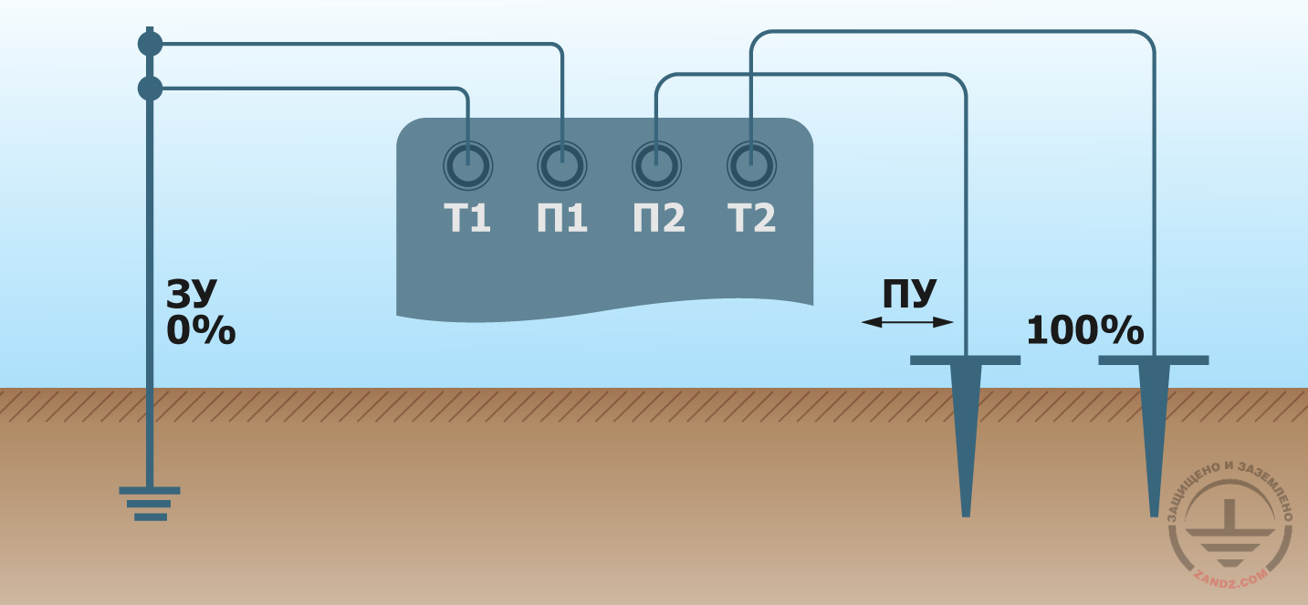
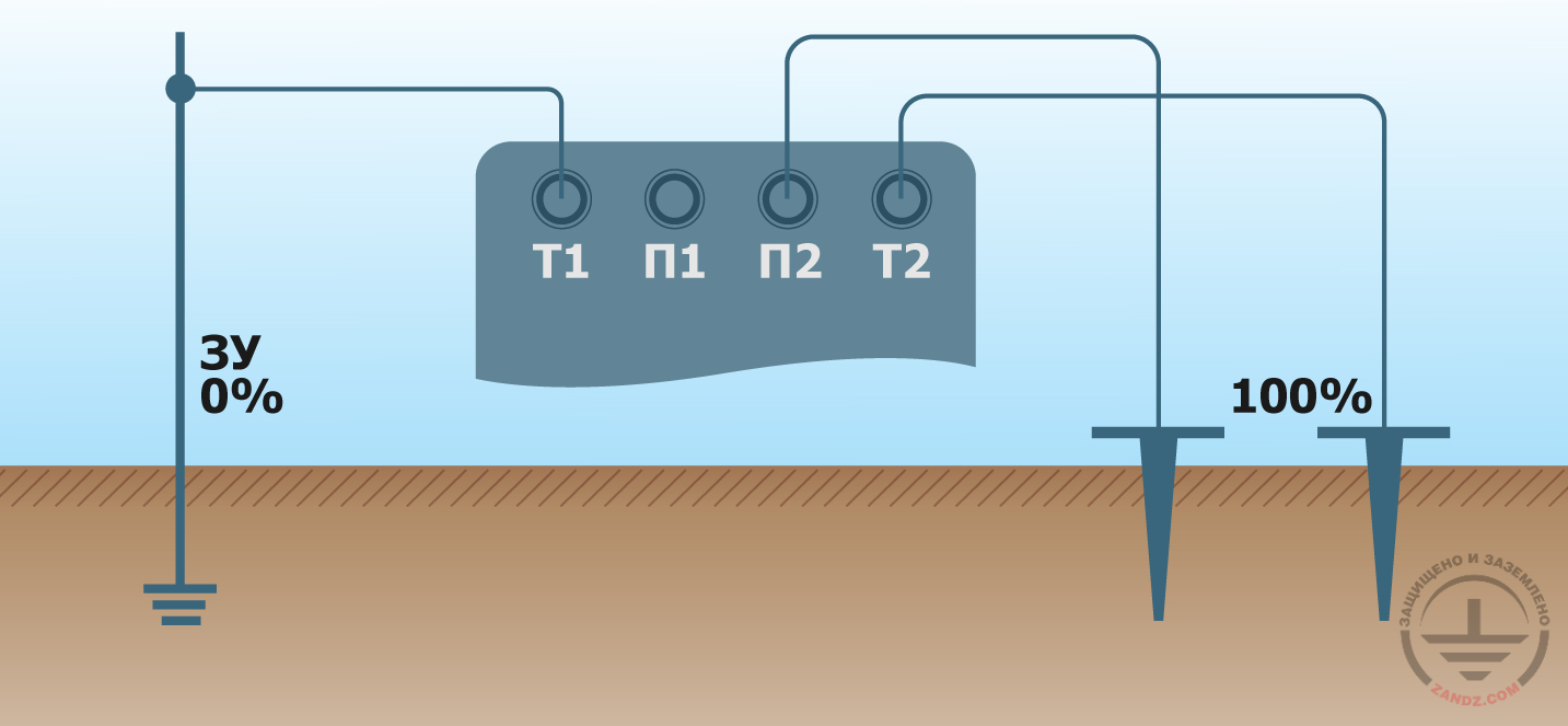
Four-wire measurement
ЗУ - GA
Typical errors when measuring the grounding arrangement resistance
Various errors may occur during measurements that affect the accuracy of the result. Some of them are as follows:
- Incorrect position of measuring electrodes: If electrodes are positioned at a wrong distance or in a wrong point, this can lead to measurement errors. Errors in positioning can lead to underestimation or overestimation of the grounding resistance.
- External factors: Environmental conditions such as humidity, temperature, or soil type can significantly affect the measurement results. For example, at high temperature, the soil may lose its conductivity, which will lead to increased resistance.
- Incorrectly used measuring devices: Some specialists may connect the devices incorrectly or select the measurement parameters incorrectly, which also leads to erroneous results. Read the instructions carefully and follow them.
- Inability to take into account the resistance of the external circuit: Sometimes specialists forget to take into account the resistance of conductors connecting the grounding arrangement and the measuring device, which can also distort the results.
- Measuring device malfunction: Using faulty devices, obsolete models, or devices not designed to measure low resistances may result in incorrect data.
Electrical safety when measuring the grounding arrangement resistance
Measuring the grounding arrangement resistance is associated with certain safety risks. Therefore, several important rules must be observed to ensure electrical safety during these operations:
- Voltage cut-off: Before the measurements, disconnect all sources of electrical current to prevent the electric shock
- Using protective equipment: Workers should wear protective shoes, gloves, and keep their distance from live objects. Insulated tools should be used to protect against accidental short circuits.
- Preliminary inspection of the equipment: Before proceeding with measurements, carefully inspect the grounding arrangement for damage, such as cracks in the insulation, rust, or loose wiring. If damage is detected, repair it to prevent any dangerous situations.
- Ensuring good communication with the operator: Resistance measurement must be carried out by a team with one of the participants (the operator) being at a safe distance from the grounding arrangement and holding responsibility for the correct activities.
- Using operating and certified devices: All measuring devices must be checked and calibrated and be accompanied by appropriate safety certificates. The devices must be protected from moisture and mechanical damage.
- Ground check: Make sure that the soil where measuring electrodes are placed to is not part of the current grounding of the facility. Additional checks may be performed to avoid short circuits.
- Regular training and drills: Electrical engineering specialists should receive regular safety training, as well as drills on working with the measurement devices.
Conclusion
Measuring the grounding arrangement resistance is an important element for ensuring the reliability and safety of electrical installations. To minimize risks to human health and life, and increase the efficiency of the grounding system, use correct measurement methods, take into account possible errors, and strictly adhere to safety measures.
Related Articles:![Guidelines for Measuring Resistance of a Grounding Arrangement]() Guidelines for Measuring Resistance of a Grounding Arrangement
Guidelines for Measuring Resistance of a Grounding Arrangement
![ZANDZ Coke Fines to Reduce Grounding Resistance]() ZANDZ Coke Fines to Reduce Grounding Resistance
ZANDZ Coke Fines to Reduce Grounding Resistance
![]()
![Measuring the Earthing Resistance Using Conventional Three- and Four-Wire Methods]() Measuring the Earthing Resistance Using Conventional Three- and Four-Wire Methods
Measuring the Earthing Resistance Using Conventional Three- and Four-Wire Methods