Why do we need it?
Grounding resistance measurement provides a basic information on its operability. Since a main tool for the protection of electrical installations is usually a grounding arrangement (GA), you cannot avoid measuring its key characteristic both upon commissioning and in regular and control tests during operations.

Basic concepts allow speaking the same language. You understand and you are understood.
According to EIC Rev. 7,grounding arrangement resistance is a ratio of voltage at the GA and the current flowing from the grounding arrangement to the ground. Note that grounding arrangement is a set of grounding arrangement and grounding conductors. It means that, during measurement, you should determine the resistance of the entire circuit constituting the grounding arrangement (term "grounding circuit" is commonly used to describe this circuit, although it is not officially used in the EIC Rev. 7).
In terms of GA, there are tests associated with commissioning and operational tests. In the former case, resistance is measured to determine whether we can bring the GA into service (along with other test types if they are provided for by the regulatory documents). In the latter case, operability of the already commissioned grounding is currently evaluated. The need for operational tests arises both because of the GA ageing and because of seasonal changes in grounding parameters associated, e.g., with soil moisture fluctuation.
Despite the fact that grounding is measured, the use of typical ohmmeters to check GAs is almost useless. To provide this type of measurements, special devices are used. They are called ground-resistance meters or simply ground testers.
Measurements may be taken with direct current, alternating current of industrial frequency (50 Hz in our country) or with high-frequency alternating current (about several hundred Hz or more). Since power energy industry is still based on alternating currents, grounding parameter measurements with direct current except for several special cases are not made. In measurements at 50 Hz, a problem of interference from leakage current at this frequency occurs, which is caused by operation of electrical installations or even power lines located nearby. This problem was solved by the possibility to manually vary operating frequency (e.g. this solution was used in the Soviet device MS-08). Measurements using high-frequency currents are quite relevant due to wide spreading of various non-linear loads, which leads to numerous harmonics in the grounding circuit.
In modern devices, resistance measurement is used with the current pulses of a meander shape with the frequency being in the range of 100 to 300 Hz (e.g. in a commonly used device ZhG-4300, 128 Hz is applied). This way, we can tune away from the interference at 50Hz and simulate real-life conditions, when the current has numerous harmonics. Additional protection from interference is achieved due to digital signal processing, in particular fast Fourier transformation.
Voltage magnitude at the GA meter terminals normally should not exceed 42 V. Due to this, measurement procedure safety for the personnel is provided.
How can we measure?
MS-08 has been a real "workhorse" for measuring GA resistance for a long time. Its production was started as long ago as in 1957, but sometimes the device is still in use. Moreover, e-stores can even offer new devices, and they are even more expensive than modern digital meters made in China. By the way, it was never announced that the production of MS-08 was stopped, so probably this legendary device is still in production.
An important advantage of MS-08 is that it does not need batteries. To measure, you should rotate a generator handle to produce alternating current. By changing the handle rotating frequency, you can vary the measurement frequency to tune away from the interference. Not only generator but also a switching device acting as a rectifier is mechanically connected to the handle. The switching device changes the polarity of connection of a tester in phase with the current generated by the generator. Due to this, interference is efficiently suppressed. The device has three measurement ranges: up to 10 Ohm, up to 100 Ohm, and up to 1000 Ohm.
In 1972, in the USSR, the production of advanced M416 meters was started, which did not require rotating the handle. Interference suppression was achieved due to the use of a synchronous detection method. Resistance measurements were possible in the range of 0.1 to 1000 Ohm; there were 4 measurement ranges. Currently, a "traditional" analog M416 device is not produced, however, a digital GA resistance meter is marketed with the same index which has nothing in common with the old device.
Among analog GA resistance meters of the Soviet times, F4103-M1 is still being produced and widely used. It can be powered both by galvanic cells and external source. Measurements are made at the frequency about 300 Hz (not controlled). The device can measure resistance of 0 to 15,000 Ohm; 10 ranges are provided.
The modern devices usually have digital indication, but there are still specialists for which needle indicators are more convenient. They appreciate a low-cost device SEW 1805R having a needle indicator. Advantages of the device measuring resistance in the range of 0.1 to 2000 Ohm (3 ranges) include low current used in measurements (2 mA vs. 80-200 mA in other devices), which sometimes allows working in live circuits. Its another feature is high operating frequency, i.e. 820 Hz. The drawback of the device is that it supports only 2-wire and 3-wire measurement schemes (it will be discussed below).
IS-20 device is a good choice for measuring in complex conditions. Its advantages include ergonomic design, protection degree IP54, multiple powering options. Range of measured resistances: 1 microOhm to 9.99 kOhm. Measurements data may be transferred to the PC in a wireless manner via Bluetooth. Operating frequency is 128 Hz, and in double-wire measurements, it is 512 Hz. It is important that the device is produced in Russia, and this fact is critical for some applications.
The modern "workhorse" for measuring GA resistance is ZhG-4300 a.k.a "Zhelesny Garry" (Iron Harry). It's lightweight (0.9 kg with batteries) and has a convenient ergonomic design. It can measure resistances of 0.05 Ohm to 20 kOm; there are 5 ranges.
Top-ranked testers include MRU-200. It can measure resistance of the protective grounding within the range of 0 to 19.99 kOhm. Protection degree IP54, an integrated NiMH 4.2 A h battery are significant advantages of working "in the field". Along with the measurement of protective grounding resistance, the device can also determine lightning protection system grounding resistance using a pulse method in the range of 0 to 199 Ohm. This GA resistance meter is produced in the EU, namely in Poland.
Note that these devices, along with their key feature, may have additional features, e.g. measurement of soil resistivity or leakage current resistance.
How can we measure resistance?
The most common methods are conventional GA resistance measurement methods based on the use of voltmeter and ampermeter with the subsequent calculation of resistance according to the Ohm's law. You can read more about these methods here.
The advantages of traditional methods include the ability to use them in any power supply system. Drawbacks include the need to disconnect grounding arrangement from the electrical installation to make measurements; impact of leakage current on measuring accuracy.
Conventional methods are 2-, 3-, and 4-wire measurements. Due to low accuracy, a 2-wire method is rarely used. A 3-wire method is easy to implement but its accuracy is inferior to that of a 4-wire method.
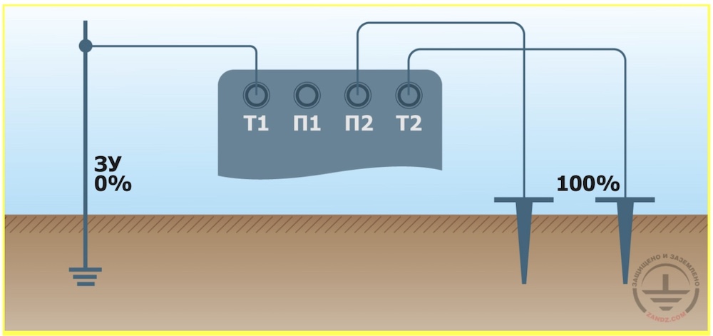
ЗУ - GA
Т1 П1 П2 Т2 - T1 P1 P2 T2
If measured GA resistance should be lower than 5 Ohm, only the 4-wire method is recommended.
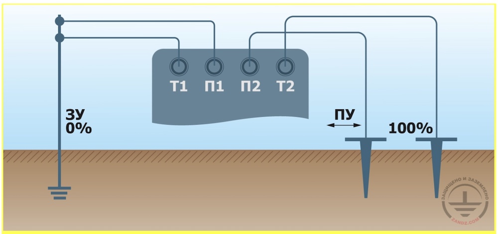
ЗУ - GA
Т1 П1 П2 Т2 - T1 P1 P2 T2
ПУ - PA
The meter has potential terminals P1 and P2 and current terminals T1 and T2. According to the 4-wire method, different wires are used from P1 and T1 to the grounding, which are connected directly at grounding terminals. In the measurements according to the 3-wire method, terminals P1 and T1 are connected with a jack, and then one wire leads from them to the grounding. If a device is initially intended for measuring only using the 3-wire method, then one terminal is provided to connect to the grounding with one wire.
Terminals P2 and T2 are connected, respectively, with the so-called potential rod and current rod. Measuring rods are recommended to be deepened into soil for at least 0.5 m. Normally the current and potential rods are located in a single line with GA.
To provide correct measurement of the distance between the rods, you should determine the maximum grounding diagonal size, D. The potential rod is installed at the distance 1.5 D but at least 20 m from the grounding electrode. The current rod is installed at the distance not exceeding 3D but at least 40 m from the grounding electrode.
However, one measurement is usually not enough to obtain the accurate result. The reason is in the soil structure irregularity. Therefore, the potential rod is installed multiple times at the distance of 20 to 80% from the initial distance between the potential and current rods. The resistance is measured every time. To provide accuracy, the more points, the better, and 10% step is sufficient. The obtained results are plotted. If the plot has a shape of a gradually increasing curve, the resistance in the section where the difference between adjacent points does not exceed 5% is taken as a final result. If the plot has a significant steep or a more complex shape, the measurements should be repeated after changing the direction of the line along which the rods are installed. Probably you will also have to increase initial distances 1.5-2 times.
Electrode-free method
It is not always possible to install current and potential rods. For example, in permafrost or when there is no space at the facility. At the same time, measurement of the power line grounding in permafrost is usually made in the period of the most severe soil freezing. Moreover, it is not always possible to disconnect the GA from the electrical installation to take measurements. Then, the electrode-free measurement method according to GOST R 50571.16-2007 is used, which is based on the use of clamp meter. It is detailed here.
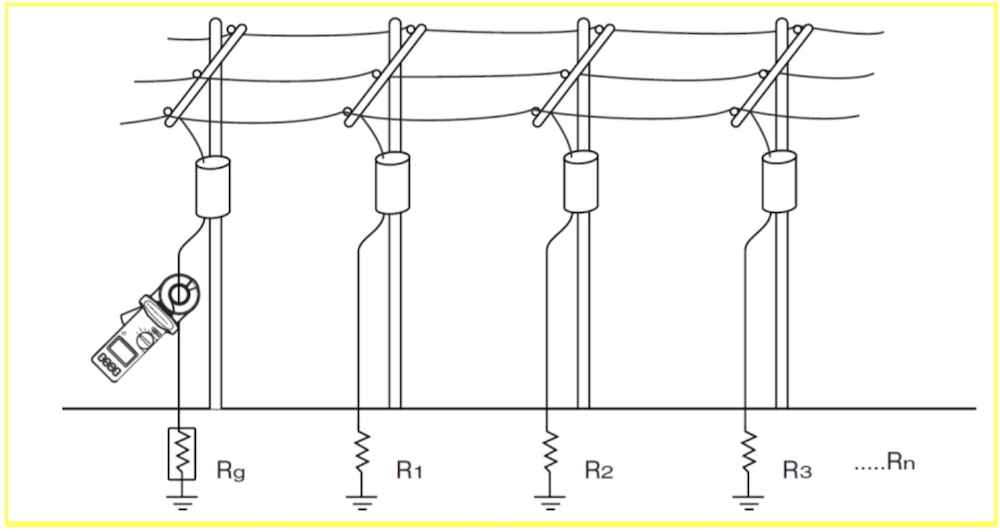
Alternating current with the set voltage and frequency different from the grid frequency is supplied to the GA from the metering generator. Current in the grounding wire is measured using special clamp meter, which is sensitive only to the frequency of the metering generator. Since voltage at the GA is known precisely, current measurements allow calculating the GA resistance according to the Ohm's law.
Note that, although it is convenient, electrode-free method in terms of measurement accuracy is inferior to the properly organized measurements using the conventional method. In particular, to supply alternating current to the circuit for measurements, a device is used that is similar to the clamp meter in terms of operating principle. To provide the required induction level, the operating frequency about 3 kHz is used, which also introduces error.
One can consider that the electrode-free method evaluates the GA resistance value from above. It means that the actual resistance value does not exceed the device indications. It is normal from the viewpoint of safety: the lower the actual resistance value, the better.
The disadvantage of the method is that it can be directly used in the TT systems and TN systems with cell grounding only. For conventional TN systems, a short-time installation of a jack between the neutral and grounding wires is required. In the entire building where the grounding is installed, you will have to disconnect the power supply for taking measurements, and there will be no more advantages compared to the conventional method.
You can consider FLUKE-1630-2 and Greenlee CMGRT-100A as examples of equipment to measure using an electrode-free method. The cost of such systems is 5 to 10 times higher than that of the devices intended for measuring resistance using a traditional method.
Requirements to devices, documentation, and laboratory staff
Since human health or even lives depend on fault-free operation of grounding, the devices considered herein should be certified for use in Russia and pass the tests. The GA resistance measurement verification period is usually 1 year or, in some cases, up to 2 years. General requirements to the personnel qualifications working with the GA resistance meter are usually provided in the technical documentation to the device.
If measurements are taken within the current electrical installation maintenance operations, the documentation is executed according to Chapter 1.8 RTOEIC.
In order for the laboratory, where the device is used, to operate within the Unified Conformance System, its organizational structure and staff qualifications should conform to the requirements of SDAE-04-2010. The laboratory should be certified according to the rules provided in SDAE-01-2010 and RTOEIC and should have the Certificate of Registration of Electrical Laboratory.
If measurements are taken by an accredited laboratory, the execution of the measurement protocol is made using GOST R 58973-2020. This GOST provides for the general rules of the document execution. A particular sample of the GA resistance measurement protocol form is called EL-8a (download form).This form conforms to the requirements of GOST R 58973-2020; however, it was not enacted by any federal regulatory act. Some time ago, a typical set of test protocol forms was created in *.doc. This is convenient, however there is no legal ground for using this form.
It is preferred to attach a copy of certificate of laboratory accreditation and a copy of certificate of meter verification to the measurement protocol. These documents provide an understanding of the competence and professionalism of the staff and the company that performed measurements.
How many Ohms should be and how often should we measure?
Some grounding resistance standards are provided in the table:
| Grounding type | Resistance, Ohm, not more than | Regulatory document | Possibility to increase in special cases |
| Electrical installations up to 1 kV with an isolated neutral wire | 4 | Item 1.7.65 EIC Rev. 7 | 10 Ohm with the generator and transformer power not more than 100 kVA |
| General spreading resistance of grounding arrangement of a 380 V 3-phase power line | 10 | Item 1.7.64 EIC Rev. 7 | 0,01ρ with soil resistivity ρ over 100 Ohm*m, but not more than 10-fold |
| Repeated spreading resistance of grounding arrangements of a 380 V 3-phase power line | 30 | Item 1.7.64 EIC Rev. 7 | 0,01ρ with soil resistivity ρ over 100 Ohm*m, but not more than 10-fold |
| Grounding of a neutral wire of a generator or a transformer in a 380 V 3-phase grid | 4 | Item 1.7.101 EIC Rev. 7 | 0,01ρ with soil resistivity ρ over 100 Ohm*m, but not more than 10-fold |
RTOEIC recommends to perform complete checks of the GA with soil recovery once every 12 years. Grounding arrangements of supports of air power lines less than 1000 V should be checked more often, once every 6 years. Moreover, grounding arrangements should be checked after the support repairs.
Standard values provided in RD 153-34.0-20.525-00 equire a complete check of GAs of power energy facilities with the frequency once every 12 years. However, after the occurrence of a short circuit or emergency at the facility, the inspection of the GA in emergency location and adjacent GA sections should be made. Moreover, which is particularly relevant in view of digitalization of power energy industry, it is recommended to check the GA after each upgrade, especially if electronic and microprocessor devices are installed. This is the reason why, along with the implementation of modern technologies in power energy industry, the devices for measuring the GA resistance will be increasingly more in demand.
You can obtain a free calculation of a grounding system or ask a question to the ZANDZ expert using the buttons below.
Related Articles: