Task:
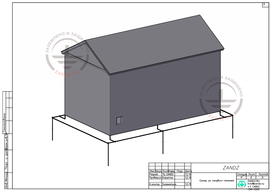
Object: sandwich-panel warehouse, 21 m long
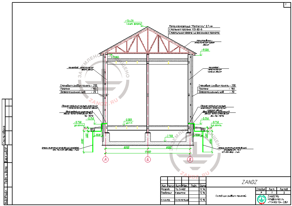
Sandwich-panels 200 mm thick with non-combustible mineral woo heat insulator is used as building envelope.
The roof of the warehouse consists of metal tiles 0,7 mm, steel hammer beams 120-60-6, roof frame of shaped iron. Electric continuity between the different parts is provided for a long term.
Soil resistivity at the object: 100 Ohm*m
Fire-hazard class - П-IIa (according to EIC).
It is necessary to make calculations and lightning protection and grounding contour project with the resistance of 10 Ohm.
Solution:
To determine the category of lightning protection, it is necessary to define the class of explosion-fire hazardous zone for premises of the designed object according to the EIC - warehouse - fire-hazard zone - П-IIa.
Expected number of lightning strikes per year into the object is defined by the formula:
N=[(S+6hоб)(L+6hоб)-7,7hоб]·n·10-6,
Where: hоб — the highest height of the object,
L — length of the object;
S — width of the object,
n — density of lightning strikes per 1 sq.km of the ground serface per year
n = 6,7·Tгр/100,
where Tгр – average duration of thunderstorms in hours.
For Moscow region, the average duration of thunderstorms is 20-40 hours.
Consequently:
N=[(S+6hоб)(L+6hоб)-7,7hоб]·n·10-6≈0,018672
Expected number of lightning strikes into the object is ≈0,018672 per year.
According to Table 1 of RD 34.21.122-87 "Instruction on arrangement of lightning protection of buildings and structures" it is necessary to arrange lightning protection of category III for warehouse premises.
As there are no special requirements on the protection of roof from damage considering the thickness of the metal more than 0,5 mm and there are no combustible materials under the rood, metal construction of the roof is taken as a natural lightning rod (see p.3.2.1.2 IS 153-34.21.122-2003).
Metal columns of the building, connected with the steel trusses of the building roof by welding are used as down conductors (see p.3.2 IS 153-34.21.122-2003).
Down conductor (column of the building) is connected to the external grounding contour by a copper-bonded tape 30x 4 (GL-11075).
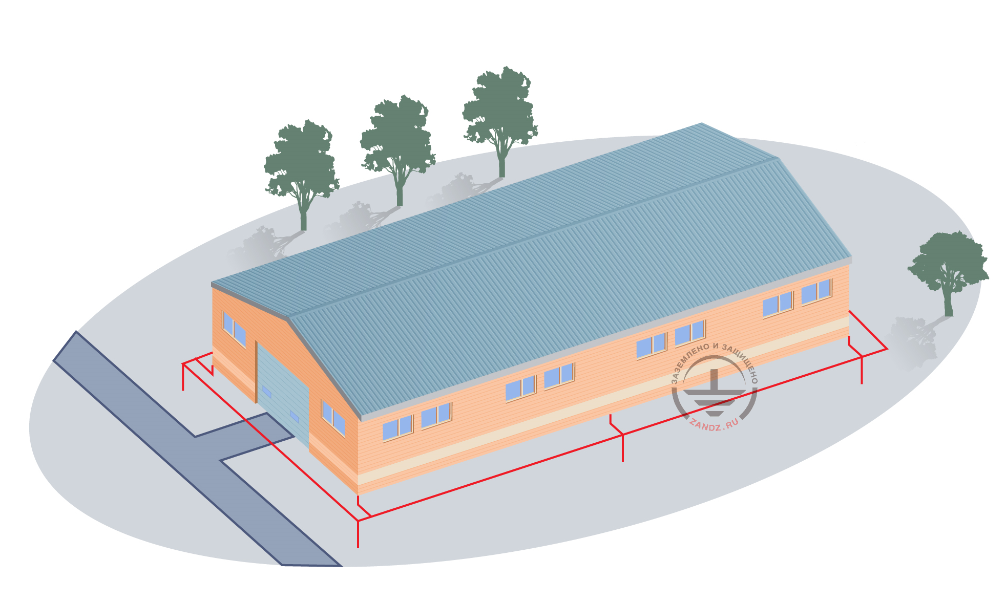
External grounding contour consists of vertical electrodes (copper-bonded threaded rods D14, 1.5m ZZ-001-065 - 2 pieces per 1 electrode) interconnected with copper-bonded tape 30x4 GL-11075 with the help of a clamp for connecting conductor ZZ-005-064.
The grounding device (external grounding contour) is laid at the depth of 0,5 m from the ground surface at the distance of 1 m from the building along the whole perimeter.
In not more than 25 m the external grounding contour is welded to the building columns.
According to p.1.7.55 of EIC, lightning protection grounding device is united with the protective grounding contour of the building's electric installations. This way, protection of the building from direct lightning strikes, secondary effects of lightning and import of high potential is provided.
In the switchboard room and ventillation chamber, there is a grounding contour made of copper-bonded tape 30x4 (GL-11075) along the perimeter at the heigh 0,4 m from the floor level. Mount the sweeps from above at the crossing of grounding contour with doors and gates.
Make mains subbranching at place.
The continuity of electric circuits must be provided in all grounding structures.
Grounding of current-using equipment, lightning devices and sockets is carried out by the PE core of the power cable.
All metal non-current carrying parts of electrical equipment, normally not under voltage but may be under it in the result of an accident or insulation damage, must be grounded by connecting them to the grounding wire of the wiring system.
Piping of all purposes must be connected to the grounding mains due to potential equalization.
Carry out installation of lightning protection and grounding according to
Calculation of grounding device resistance:
Resistance of a horizontal electrode:

ρ - soil resistivity, Ohm* m;
b - horizontal electrode tape width ,m;
Lгор - horizontal electrode length, m.
Resistance of a vertical electrode:

where ρ - equivalent soil resistivity, ohm · m;
L - length of the vertical electrode, m;
d - vertical electrode diameter, m;
T- deepening - distance from the ground surface to the ground electrode, m;

where t - deepening of the electrode top, m
Impedance of the grounding device:

where n - number of kits;
Kисп - utilization ratio;
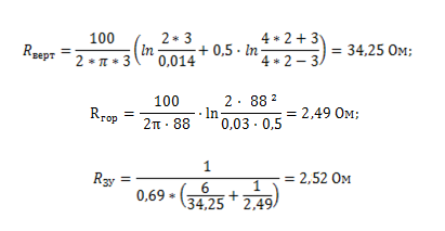
The design resistance of the grounding device is 2.52 ohms, which is less than the permissible resistance of 10 ohms.
The list of required materials:
| № | Fig | Product item | Name | Q-ty | Weight, unit, kg |
| 1 |  |
ZZ-001-065 | ZANDZ Copper-bonded threaded grounding rod (D14; 1,5 m) | 12 | 1,9 |
| 2 | 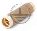 |
ZZ-002-061 | ZANDZ Threaded coupler | 6 | 0,08 |
| 3 | 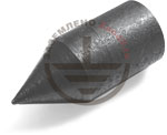 |
ZZ-003-061 | ZANDZ Starting tip | 6 | 0,07 |
| 4 | 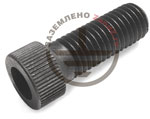 |
ZZ-004-060 | ZANDZ Driving head for a breaker hammer | 3 | 0,09 |
| 5 | 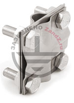 |
ZZ-005-064 | ZANDZ Clamp for connecting conductor (up to 40 mm) | 50 | 0,31 |
| 6 | 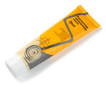 |
ZZ-006-000 | ZANDZ Conductive grease | 2 | 0,19 |
| 7 |  |
ZZ-007-030 | ZANDZ Water-proof tape | 2 | 0.442 |
| 8 |  |
ZZ-008-000 | ZANDZ Cap for a breaker hammer (SDS max) | 1 | 0.48 |
| 9 | 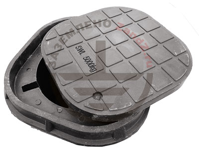 |
GL-11402 | GALMAR Inspection pit | 6 | 2.6 |
| 10 | 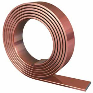 |
GL-11075 | GALMAR Copper-bonded steel wire 30х4 mm | 150 | 0,98 (in meters) |
| 11 | — | Anchor-wedge 6x60 mm | 105 |
Appendix: the project is available in DWG and PDF formats
Files in the formats DWG and PDF are available for downloading only for authorized users.
Do you need to make the project on grounding and lightning protection? Order it by contacting the ZANDZ Technical Center!
Any more questions on the calculation left? Ask them in the comments to this page!
Related Articles:
 Why did a whiskey storage burn out in Kentucky?
 Lightning warning system


