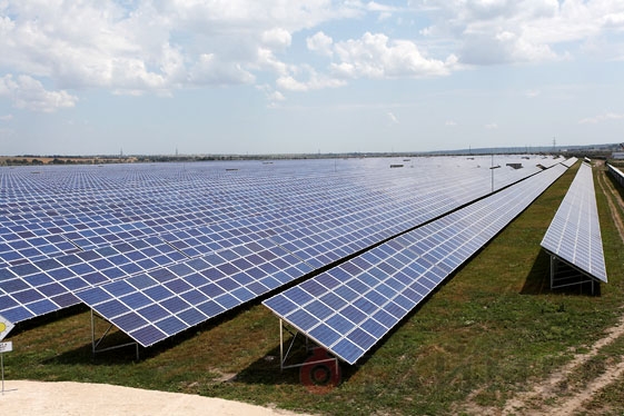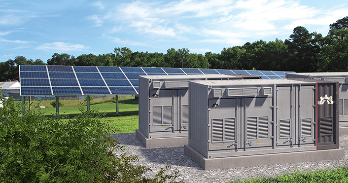
Modular inverter installations (MII) provide power from large arrays of solar panels. This is an important component of human life since these plants serve as electricity sources. Recently, Technical Center ZANDZ received a request for the analytical description of a block-modular inverter installation. Let us continue with more detailed review of our offered solution
Computations of lightning protection of a modular inverter installation (MII) for a solar power station
Object: modular inverter installation (MII) for a solar power station.

Figure 1 – Object layout.
Task: Make calculations of the lightning protection system for a modular inverter installation (MII) for a solar power station.
Protection of the buildings and structures against lightning strikes is provided by using lightning dischargers. The lightning discharger – is a device that is elevated over the considered object, through which the lightning current goes into the ground bypassing the protected object. It consists of a interception rod, which is specially designated to arrest the lightning discharge, a conductor cable and a ground electrode.
Solutions to assure the requirements for a lightning protection system for a modular inverter installation (MII) for a solar power plant:
- Anti-lightning protection is made in accordance with the 7th edition., of the Electrical Installations Code (EIC), SO 153-34.21.122-2003 "Instructions on the measures for lightning protection of buildings, structures, and industrial communications" (further in the text – SO) and Working Documentation 34.21.122-87 "Instructions on the measures for lightning protection of buildings and structures" (further in the text – WD).
- The object belongs to the class II of lightning protection The reliability of the system should be no less than 0.95.
- Lightning protection of the object is performed using 6 tower interception rods with a height of 1.5 m (GL-21134) mounted by the wall brackets.
- Galvanized steel wire d8 mm (ZZ-502-008) is used as main conductor cable.
- Mounting of the main conductor cables is performed with the terminal GL-11747A – on the roof and vertical surfaces. The accepted pitch of terminals is 0.8-1.0 m.
- The universal terminal GL-11551A is used to connect rolled products along the length and in joints.
- Galvanized steel electrodes 3 m long in the places of main conductors downdrops are used as vertical ground electrodes. A galvanized steel strip with a cross section of 30x4 mm, combining all vertical electrodes is used as a horizontal ground electrode. The distance to the object foundation is at least 1 m. The strip embedment is 0.5 to 0.7 m.
- According to EIC-7 edition, P.1.7.55 –Grounding arrangements for protective grounding of electrical installations in buildings and structures and 2nd and 3rd classes of lightning protection of these buildings and structures should be generally common.
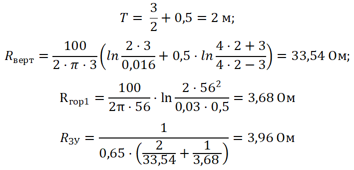
- The calculated resistance value of the grounding arrangement is 3.96 ohms.
- In the availability of reinforced concrete structures, they must be attached to the main conductors/grounding arrangement.
- Connection to the grounding arrangement is made through the terminals ZZ-005-064.
Results of the calculations performed by using the software developed by OAO G.M. Krzhizhanovskiy Energy Institute (OAO ENIN):
- The density of lighting discharges into the ground is 4 strokes/sq.km per year.
- The total number of strokes in the system – is 0.0042 (every 238 years).
- The total number of breakthroughs is 0.0000047 (every 212766 years).
- The probability of a breakthrough into system objects – is 0.0011.
- The system's reliability – is 0.9989.
 :
:
The rated resistance of the grounding arrangement is 3,96 ohms.
Figure 2 shows hardware layout.
Table 1 includes the list of required hardware and materials.
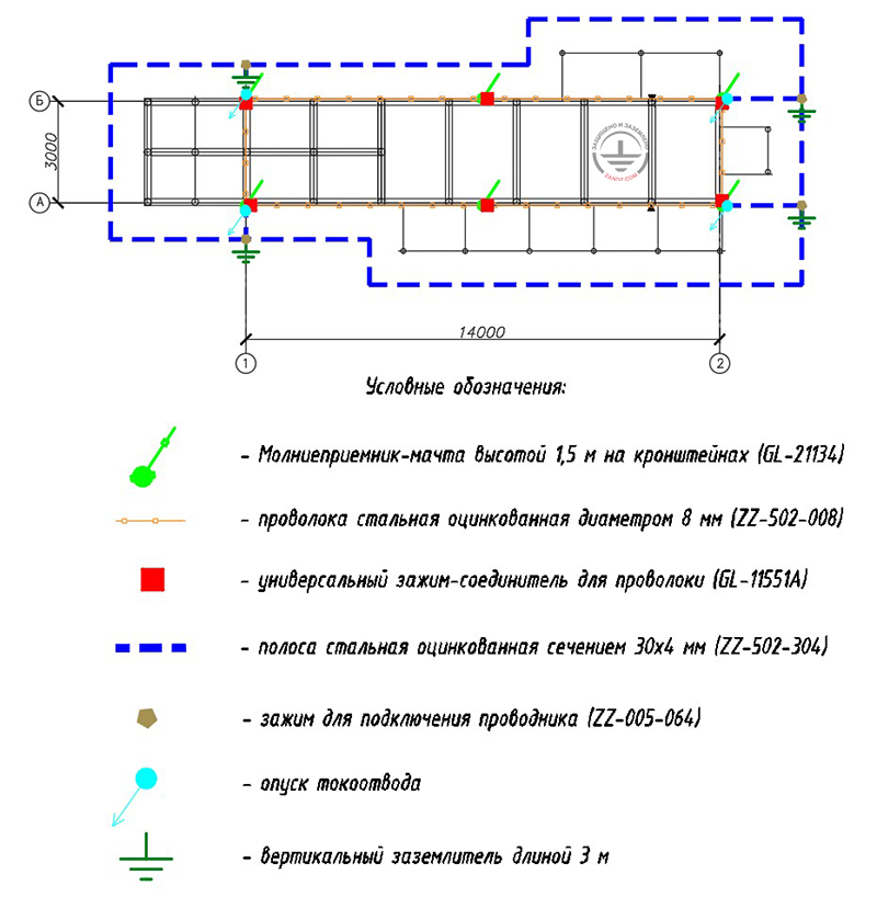
Figure 2 – Layout of equipment for protection of a modular inverter installation (MIU) against lightning for a solar power station.
Условные обозначения - Conventional symbols
Молниеприемник-мачта высотой 1,5 м на кронштейнах (GL-21134) - 1.5 m interception rod of tower type fastened with brackets (GL-21134)
Проволока стальная оцинкованная диаметром 8 мм (ZZ-502-008) - Galvanized steel wire with a diameter of 8 mm (ZZ-502-008)
Универсальный зажим-соединитель для проволоки (GL-11551A) - Universal Wire Connection Terminal (GL-11551A)
Полоса стальная оцинкованная сечением 30х4 мм (ZZ-502-304) - Galvanized steel strip with a cross-section of 30x4 mm (ZZ-502-304)
Зажим для подключения проводника (ZZ-005-064) - Main conductor connection terminal (ZZ-005-064)
Опуск токоотвода - Main conductor cable downdrop
Вертикальный заземлитель длиной 3 м - Horizontal ground electrode 3 m long
Table 1 – List of material requirements.
Do you have any questions about lightning protection of (block-)modular buildings or other facilities? Request for assistance in the Technical Center ZANDZ!
Related Articles: