May 22, 2017
Environmental pollution has caused the research to find solutions to reduce air emissions which leads to an increase in the EV used. Electric vehicles need battery recharge; therefore, the number of charging stations increases proportionally.
As any electrical installation, charging stations need a high-quality grounding and protection from external hazards, e.g. direct lightning strike.
Our Technical Center has received a request to calculate the lightning protection and grounding system for EV charging stations. We offer the following solution for this task:
Initial data:
- facility - EV charging station;
- soil type used for calculations - clay loam (100 Ohm*m);
- dimensions are shown in Figure 1.
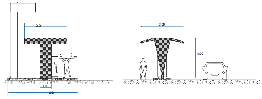
Figure 1. Facility dimensions (in mm)
Task:
- calculate the system of external lightning protection;
- calculate the grounding arrangement.
The activities were performed in accordance with the Electrical Installations Code (EIC) Rev. 7, SO 153-34.21.122-2003 Guidelines for Arrangement of Lightning Protection of Buildings, Structures, and Industrial Utilities (hereinafter referred to as SO) and RD 34.21.122-87 Guidelines for Arrangement of Lightning Protection of Buildings and Structures (hereinafter referred to as RD).
Protection of buildings against lightning strikes is provided by using lightning arresters. Lightning arrester is a device that is elevated over the protected facility through which the lightning current goes into the ground bypassing the protected facility. It consists of a lightning rod that directly accepts the discharge of a lightning , a current collector, and a grounding electrode.
The station is classified as conventional in terms of lightning protection as per SO and to Category III as per RD. The required system reliability is at least 0.9.
According to the EIC Rev. 7, item 1.7.103, total dissipation resistance of ground terminals (including natural ones) of all repeated groundings of the PEN wire of each high-voltage line in any season of the year should not exceed 10 Ohm, respectively, with linear voltages 380 V of a three-phase source or 220 V of a single-phase source.A set of measures to meet the necessary requirements to the lightning protection and grounding systems includes the following solutions:
- Installation of one 10 m lightning rod at the distance of 3 m from the facility (see Fig. 2);
- Installation of a grounding arrangement, comprising 5 x 2 m vertical electrodes combined with a horizontal electrode (copper-plated strip 30 x 4 mm). The distance between the vertical electrodes is at least 5 meters, the distance from the electrode to the foundation of the charging station is at least 1 m, the depth is 0.5 to 0.7 meter.
Ground terminal resistance calculation:
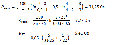
Верт - Vert
Ом - Ohm
Гор - Hor
ЗУ - GA
The calculated resistance of the grounding arrangement is 5,41 Ohm which is less than allowed resistance of 10 Ohm.
The occurrence of lightning strikes into the ground is 4 strikes/sq. km per year;
The total number of strikes into the system is 0.013 (once every 77 years);
The total number of blowouts is 0.00019 (once per 5,263 years);
The system's reliability is 0.985;
The probability of breakout into all facilities of the system is 0.015.
The results of calculation of protection zones according to SO:
Lightning mast No. 1 (ZZ-201-010):
h = 10 m;
Cone height according to SO, Table 3.4:
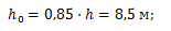
- Молниеприемник – мачта высотой 10 м - 10 m lightning mast
- Полоса омедненная стальная сечением 30х4 мм - Steel copper-plated bar 30 x 4 mm
- Электрод D=14 мм, L =3 м. - Electrode D = 14 mm, L = 3 m.
Cone radius according to SO, Table 3.4:

Direct lightning strike protection zone is shown in Fig. 2.
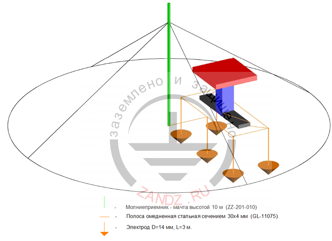
Lightning mast is a 10 m high mast - air terminal mast 10 m high; copper-bonded steel tape with the cross-section of 30 x 4 mm; Electrode D = 14 mm, L= 3 m.
Figure 2. Equipment layout. Protection zone
The list of necessary materials is given in Table 1.
Table 1. List of needed materials.
| Item # | Fig. | Part number | Product | Quantity, pcs |
| 1. |  |
ZZ-201-010 | ZANDZ 10 m vertical lightning rod (galvanized steel; with parts embedded under the foundation) | 1 |
| 2. |  |
ZZ-001-065 | ZANDZ Copper-plated threaded grounding rod (D14; 1.5 m) | 10 |
| 3. |  |
ZZ-002-061 | ZANDZ Threaded connecting coupling | 6 |
| 4. |  |
ZZ-003-061 | ZANDZ Takeoff Tip | 5 |
| 5. |  |
ZZ-004-060 | ZANDZ Guide head for jackhammer attachment | 2 |
| 6. |  |
ZZ-006-000 | ZANDZ Conductive grease | 1 |
| 7. |  |
ZZ-008-000 | ZANDZ Attachment to the jackhammer (SDS max) | 1 |
| 8. |  |
ZZ-005-064 | 6 | |
| 9. |  |
GL-11075-20 | GALMAR Copper-plated bar (30 * 4 mm / S 120 mm²; bundle 20 meters) | 2 |
Installation of a standalone 10 m lightning rod provides the lightning protection reliability for Category II which is, in turn, a good indicator, and reduces the lightning breakthroughs number to once in 5,263 years.
The use of copper-plated grounding arrangements as a circuit along the facility perimeter with vertical electrodes will allow providing a reliable grounding for the electrical installation for at least 30 years!
Use professional solutions together with ZANDZ!
Also read::
- Efficiency of Lightning Rods and Conductors Design
- What Lightning Protection Volume Should Residential and Public Buildings Have?
- How to Choose a Lightning Rod Based on RF Regulatory Documents?