11.01.17
Practically all buildings and structures where people live or work must be equipped with a lightning protection system. The purpose of buildings varies in the same way as the consequences of a lightning strike and the level of responsibility for the organization of lightning protection. But there are institutions for which it is absolutely vital to ensure protection against any hazards, and that is absolutely obvious without any regulatory documents and ordnances. It is definite that kindergartens and public nurseries must be among such facilities.
Being not only an educational institution, but also a place where little children are constantly located, a kindergarten is simply obliged to ensure protection against lightning. The parents’ and staff’s awareness of reliable lightning protection installed on the building imparts calmness and confidence in the kids’ safety in any weather.

Let’s see how to ensure proper protection of a kindergarten against lightning using an example.
Sample calculation
A kindergarten is the object of installation for lightning protection and earthing.
The activities were carried out in accordance with theEIC 7 th ed. Chapter 1.7, SO 153-34.21.122-2003 "Instructions for the lightning protection of buildings, structures and industrial communications" (hereinafter SO) and RD 34.21.122-87 "Instructions for the lightning protection of buildings and structures" (hereinafter RD).
The building being protected is an ordinary structure in terms of lightning protection as per the IS and is in Category 3 according to the AD.
Buildings are protected against lightning strikes by lightning rods. A lightning rod is a device rising above the facility that diverts the lightning current into the ground without entering the facility. It comprises an interception rod that directly takes on the lightning discharge, a conductor wire and an earthing rod.
Required arrangements for lightning protection
The action plan to ensure compliance with the necessary requirements for a lightning protection system is as follows:
- Installation of 6 (six) 4-meter-high rod-shaped interception rods. It is taken into account that 0.5 meter of the rod length is used for fastening.
- Installation of 2 (two) 4-meter-high rod-shaped interception rods. It is taken into account that 0.5 meter of the rod length is used for fastening.
- Interception rods are interconnected to arrange two conductor wires, using copper-plated wire of D=8 mm from each interception rod. The conductor wires are connected to the artificial ground conductor. The conductor cables are mounted as follows (installed 0.6-1 m apart):
- to the wall by means of GL-11703A clamps;
- on the roof – with GL-11747A clamps.
- GL-11551A clips are used to connect and branch the down conductors.
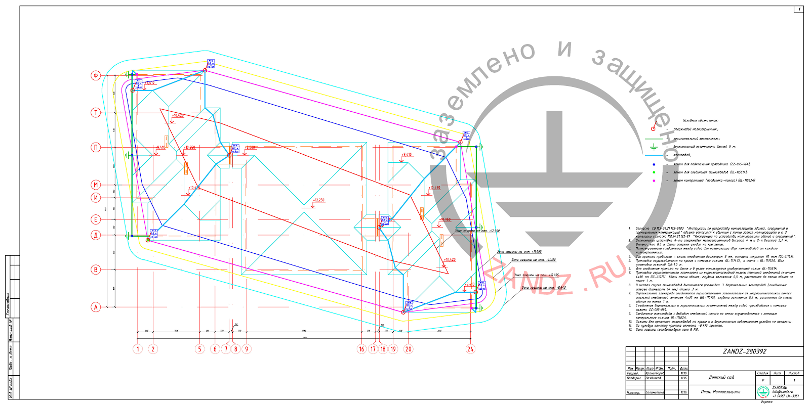
Figure 1 – Plan with the layout of lightning protection and earthing elements
Earthing device
The complex of measures to ensure compliance with the necessary requirements for the earthing device is as follows:
- Assemblage of two earthing devices comprising three 3m-long vertical electrodes (copper-plated rods of 14 mm in diameter) integrated with a horizontal electrode (copper-plated band of 4x30 mm cross-section). The distance between the vertical electrodes is at least 3 meters, the distance from the horizontal electrode to the building walls - 1 m, the depth - 0.5 m.
- Vertical and horizontal electrodes are connected with the ZZ-005-064 clamp.
- The down conductor is connected with the output of the copper-plated band from the ground with the help of the clamp GL-11562A.
The layout of elements in the lightning protection system and the earthing device is depicted in Figures 1 and 2. Protection zone corresponding to zone B of the AD, is shown in Figure 3.
Figure 2 – A sketch with the layout of elements of lightning protection and earthing
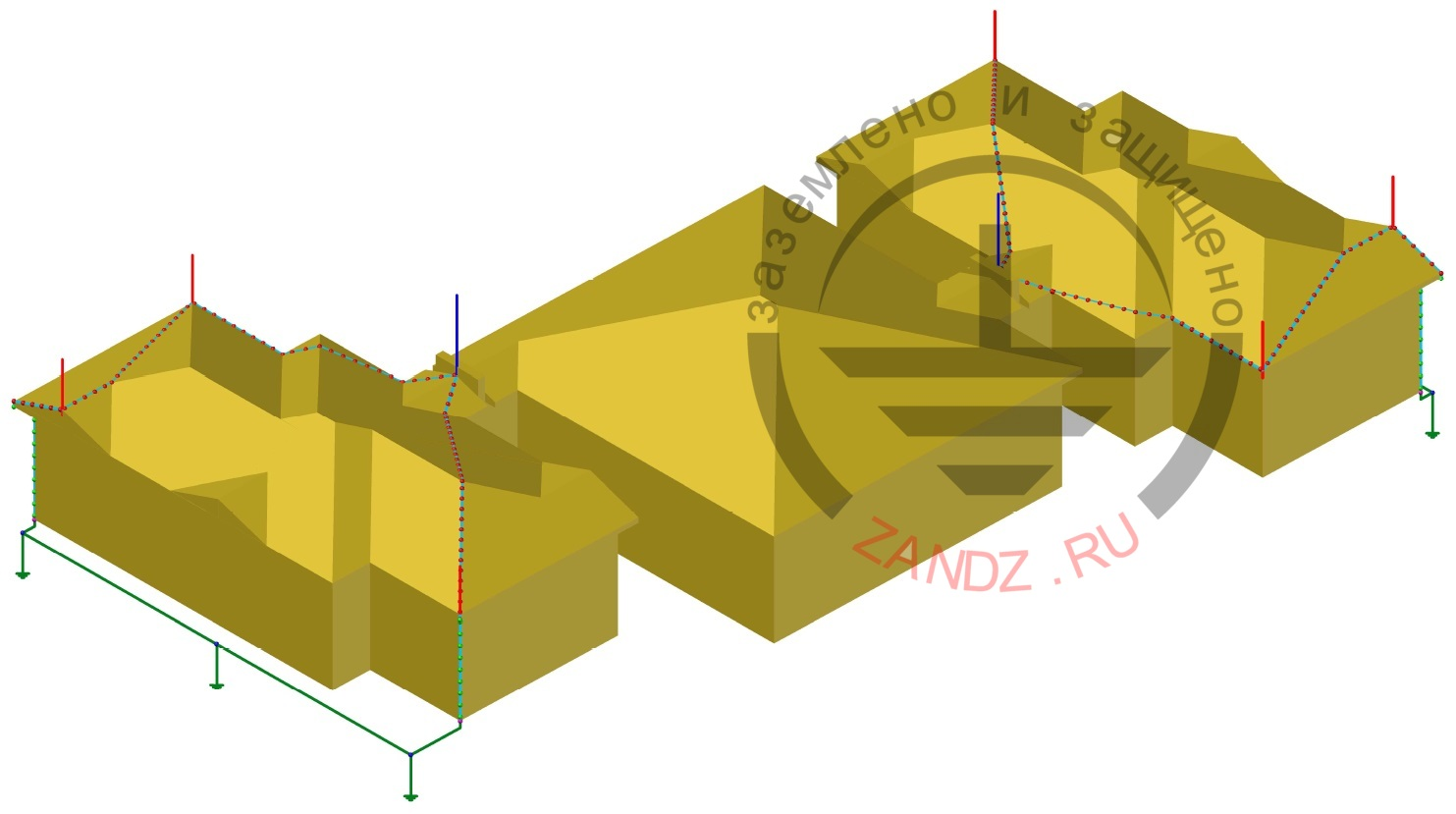
Figure 3 – Protection zone which corresponds to zone B in RD 34.

Calculation of a grounding device
In accordance with the EIC (PUE) 7th edition, par. 1.7.103, the total resistance of spreading of ground electrodes (including natural ones) of all repeated groundings of the PEN conductor of every overhead transmission line at any time of the year should be not more than 10 ohms with line voltages of 380 V for a three-phase power source or 220 V for a single-phase power source.
Lightning protection is calculated using the software developed by the Krzhizhanovsky Power Engineering Institute. The calculated value of the specific resistance of loam-type soil is taken to be 100 Ohm∙m.
The design resistance of the earthing device with the borehole taken into account equals 4.23 Ohm, which is less than the required value of 10 Ohm.
Table 1. List of required materials for lightning protection and earthing


Internal lightning protection (SPD)
To protect equipment and electric communications inside a building, we recommend providing for a complex of measures that rule out the impact of hazardous overvoltages.
1. Protection in the master distribution board
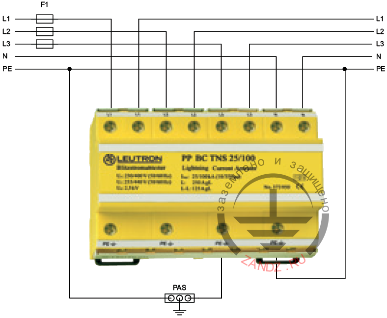
In the main distribution board, a surge protection device (SPD) of class I+II+III PP BCВ TNS 25/100 is installed, selected in compliance with the three-phase input to the house and the power supply system TN-C-S or the TN-S.
The connection is made in series (V-connection). We recommend using standard F1 fuses (see the diagram) at a nominal rating of up to 125A.
If a local switch (or protective fuses instead of it) designed to withstand mains power is installed and its nominal rating is less than 125 A, then additional F1 fuses are not required.
SPD connecton diagram is shown in Figure 4.
Figure 4– Diagram of connection of the surge protection device of class 1+2+3
2. Protection in floor/secondary distribution boards
When the distance between the main and floor distribution board is over 10 m, a surge protector of the II class EP C TNS 275 is installed in the floor distribution boards.
The connection is made in series (V-connection). We recommend using standard F1 fuses (see the diagram) at a nominal rating of up to 125A.
If a local switch (or protective fuses instead of it) designed to withstand mains power is installed and its nominal rating is less than 125 A, then additional F1 fuses are not required.
SPD connecton diagram is shown in Figure 5.

Figure 5– Diagram of connection of the class 2 surge protection device
Table 2. List of required materials for internal lightning protection
|
№ |
Photo |
Product item |
Name |
Quantity, pcs. |
|
1.
|
 |
LE-373-960 |
1 |
|
| 2. |  |
LE-381-178 | LEUTRON Overvoltage suppressor (surge protector) EP C TNS 275 | According to the number of floor distribution boards |
Lightning protection of the facility is considered incomplete without the stated measures, because only the use of protective devices makes it possible to reduce overvoltages in the mains to a level safe for equipment.
If you have any questions on the lightning protection of preschools and educational institutions, contact the ZANDZ Technical Center !
See also: